Onset Computer ONST6 HOBO RX Wireless Sensor Network User Manual 22245 2 RXW WCF Manual
Onset Computer Corporation HOBO RX Wireless Sensor Network 22245 2 RXW WCF Manual
Contents
- 1. User Manual_22241-2 RXW-SMx Manual.pdf
- 2. User Manual_22242-2 RXW-THC Manual.pdf
- 3. User Manual_22243-3 RXW-TMB Manual.pdf
- 4. User Manual_22244-2 RXW-RGx Manual.pdf
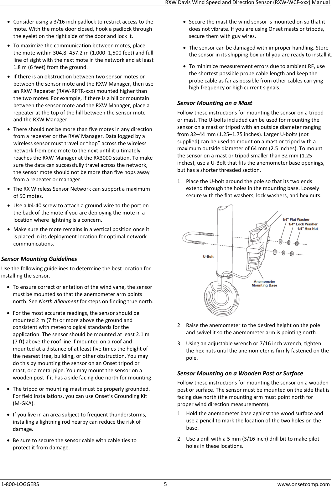
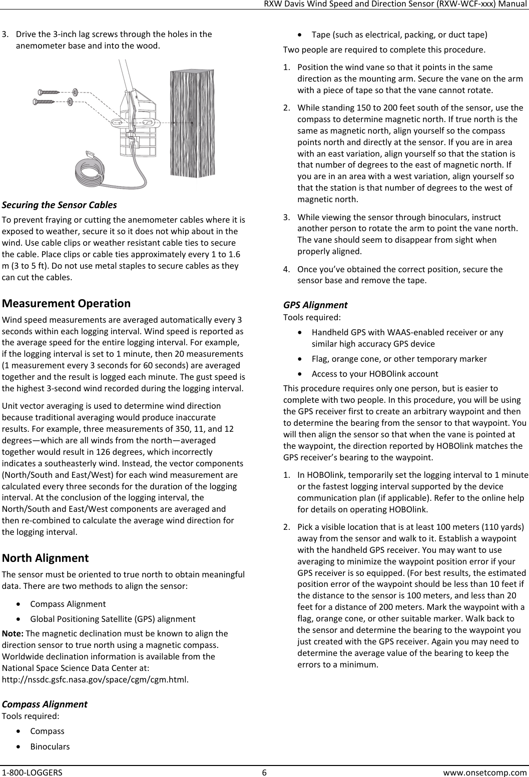
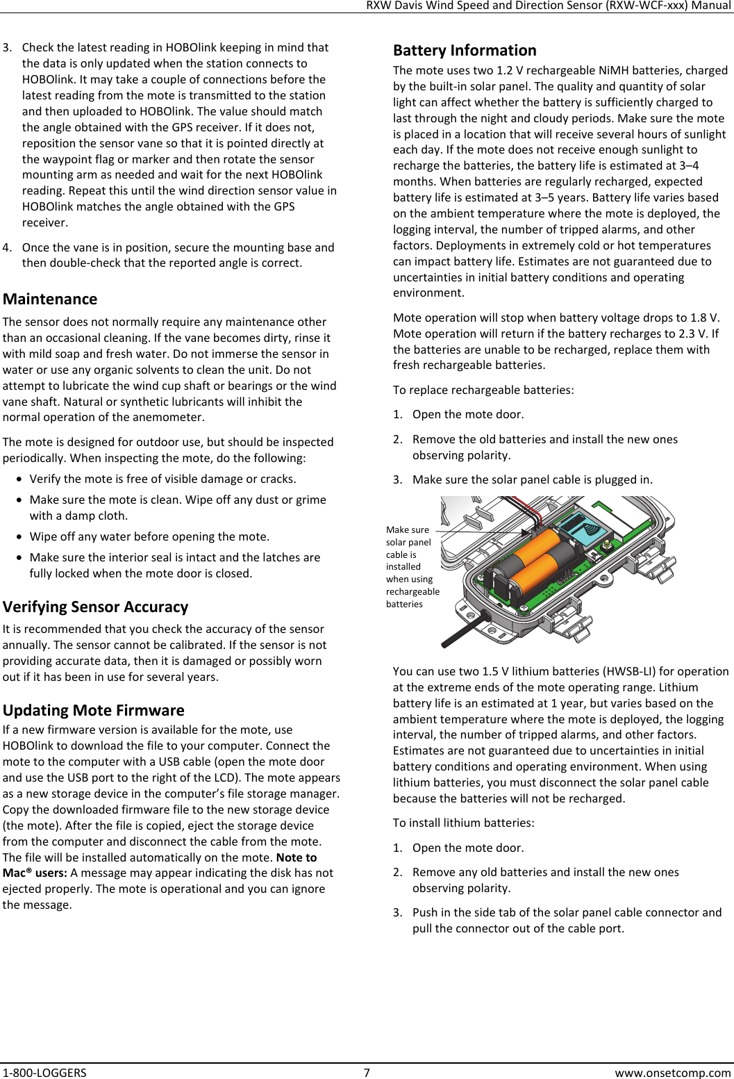
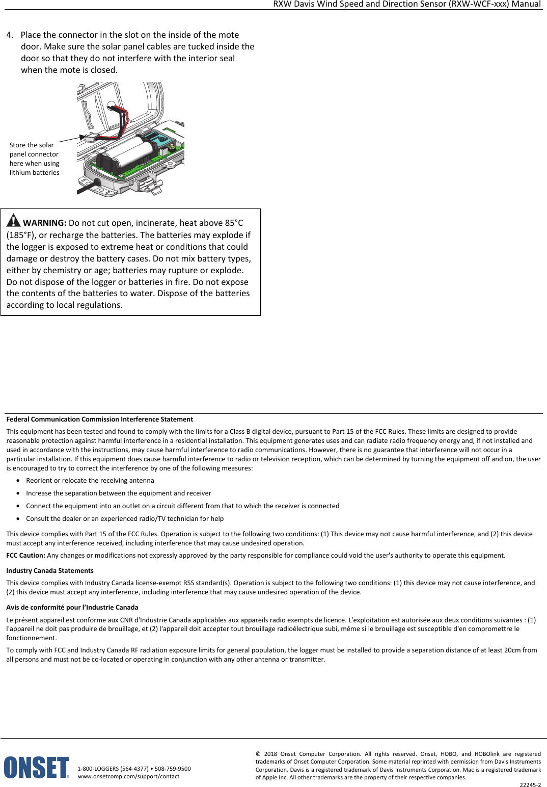
- 5. User Manual_22245-2 RXW-WCF Manual.pdf
- 6. User Manual_22246-2 RXW-LIA Manual.pdf
- 7. User Manual_22247-2 RXW-LIB Manual.pdf
- 8. User Manual_22248-2 RXMOD-RXW Manual.pdf
- 9. User Manual_22249-2 RXW-RPTR Manual.pdf
- 10. User Manual_22436-1 RXW-OBUS Manual.pdf
- 11. User Manual_22437-1 RXW-ANA Manual.pdf
- 12. User Manual_22438-1 RXW-SPER Manual.pdf
User Manual_22245-2 RXW-WCF Manual.pdf