POWER ONE ITALY DESK Radio equipment for inverter check User Manual Aurora Desktop ver 1 1 EN
POWER-ONE ITALY SPA Radio equipment for inverter check Aurora Desktop ver 1 1 EN
UserManual.wiki
>
POWER ONE ITALY
>
DESK User Manual
PVI-DESKTOP-US UserMan
Navigation menu
Upload a User Manual
Namespaces
Wiki Guide
HTML
PDF
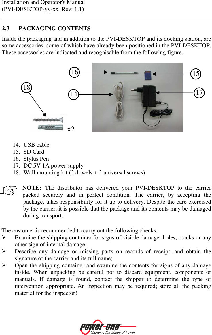
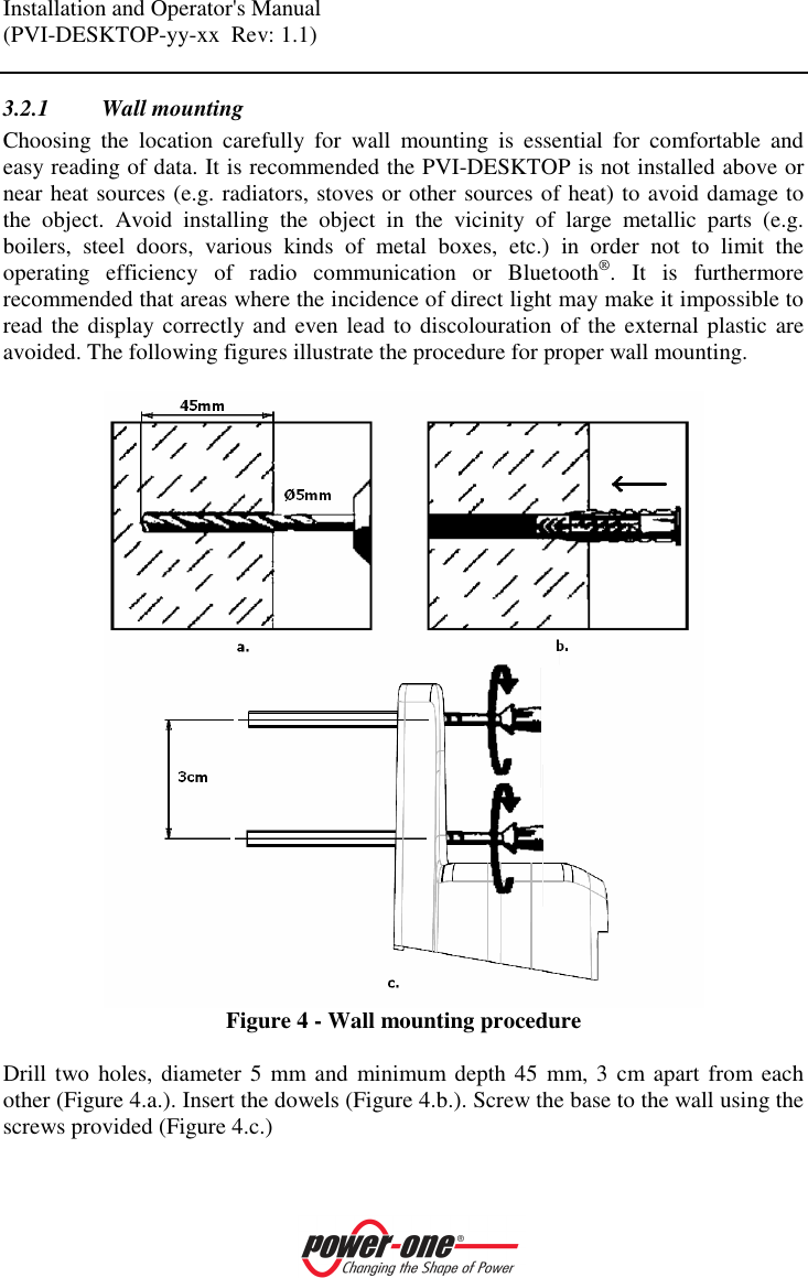
Info
Views
User Manual
Discussion / Help
Navigation