POWER ONE ITALY DESKNOP RADIO EQUIPMENT FOR INVERTER CHECK WITHOUT FHSS User Manual Aurora Desktop ver 1 2 EN
POWER-ONE ITALY SPA RADIO EQUIPMENT FOR INVERTER CHECK WITHOUT FHSS Aurora Desktop ver 1 2 EN
UserManual.wiki
>
POWER ONE ITALY
>
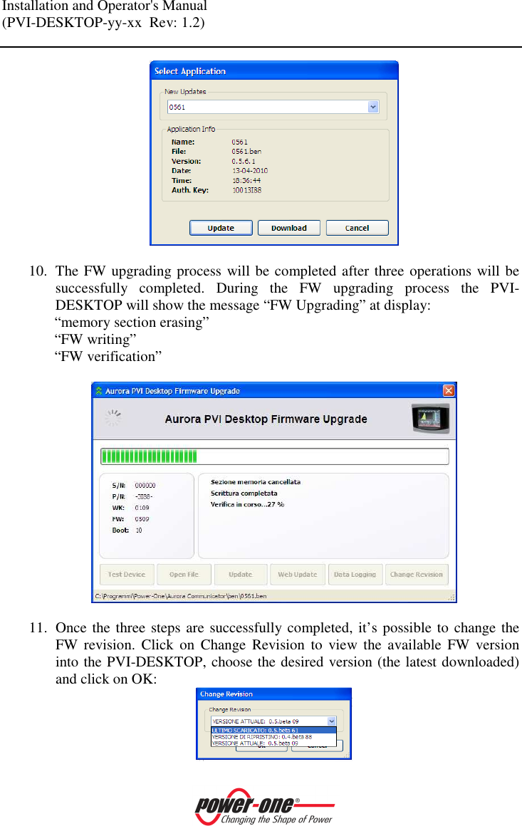
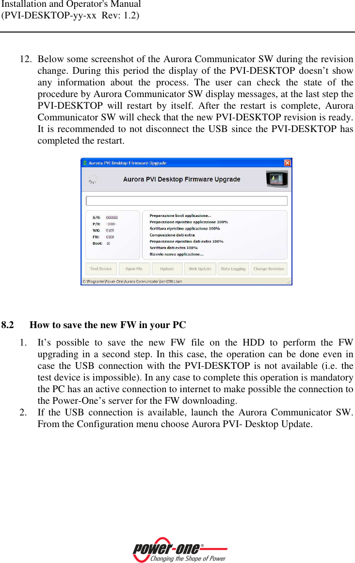
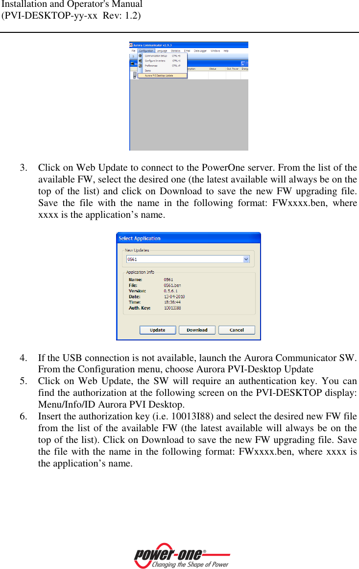
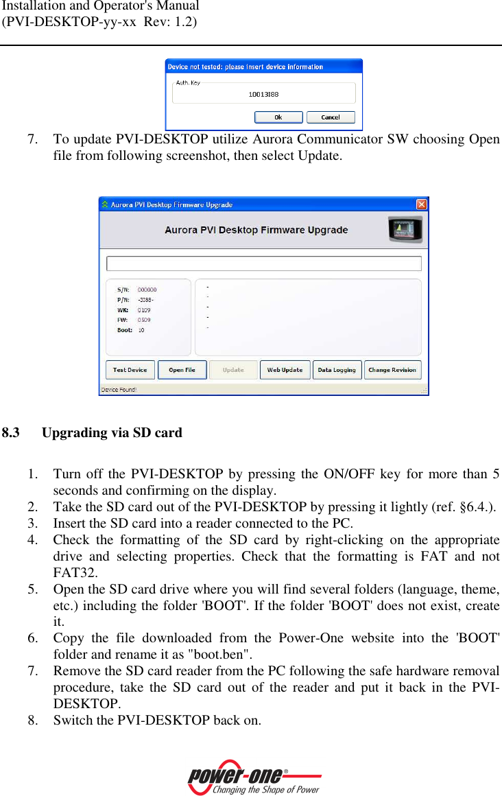
DESKNOP User Manual
PVI-DESKTOP-US UserMan
Navigation menu
Upload a User Manual
Namespaces
Wiki Guide
HTML
PDF
Info
Views
User Manual
Discussion / Help
Navigation