Panasonic Devices Europe 1315 Bluetooth Module User Manual TABLE OF CONTENTS
Panasonic Industrial Devices Europe GmbH Bluetooth Module TABLE OF CONTENTS
UserManual.wiki
>
Panasonic Devices Europe
>
1315 User Manual
>
15_PAN1315 UserMan
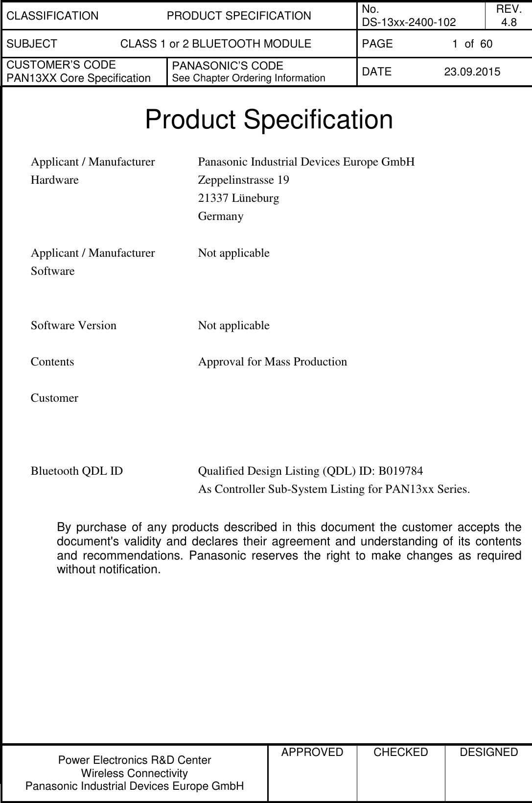
Contents
1.
UserMan
2.
Updated OEM instruction for module integration
3.
Updated OEM instruction to design and/or use of antennas KDB 996369 Question 11
4.
15_PAN1315 UserMan
15_PAN1315 UserMan
Navigation menu
Upload a User Manual
Namespaces
Wiki Guide
HTML
PDF
Info
Views
User Manual
Discussion / Help
Navigation
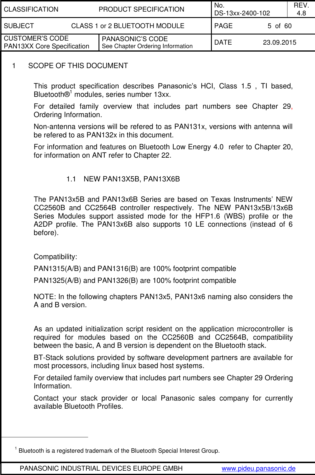
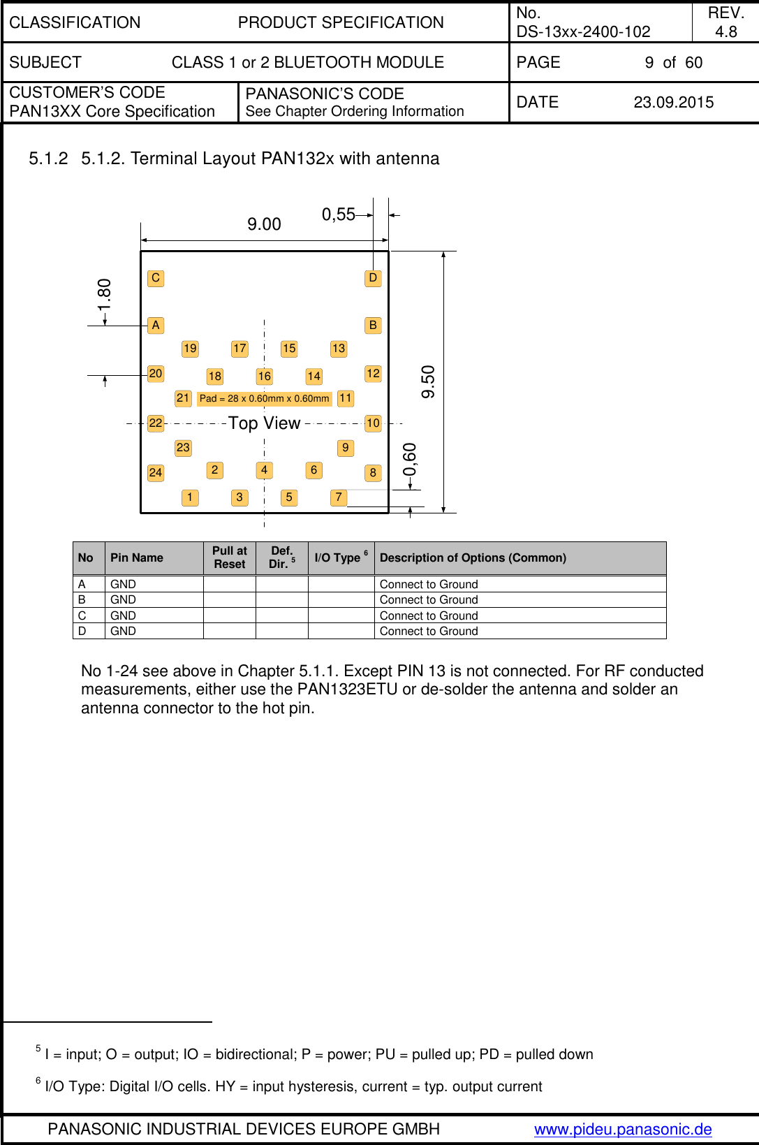
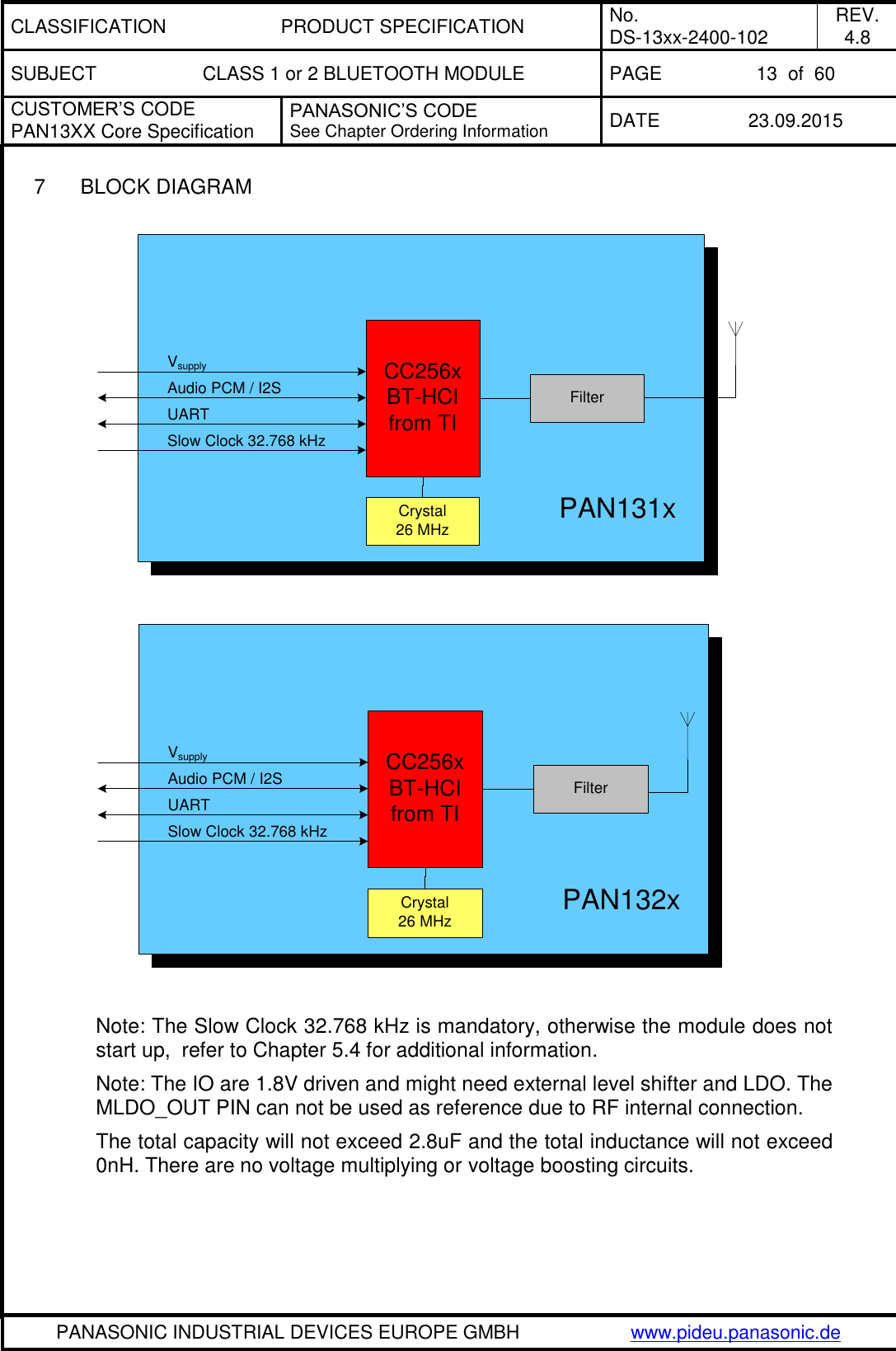
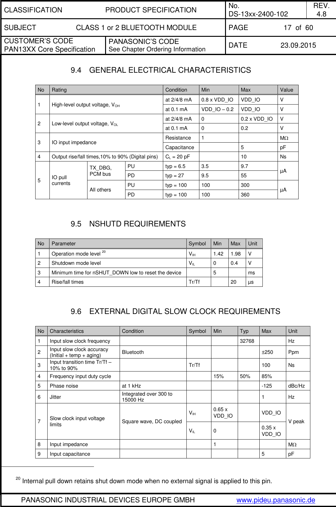
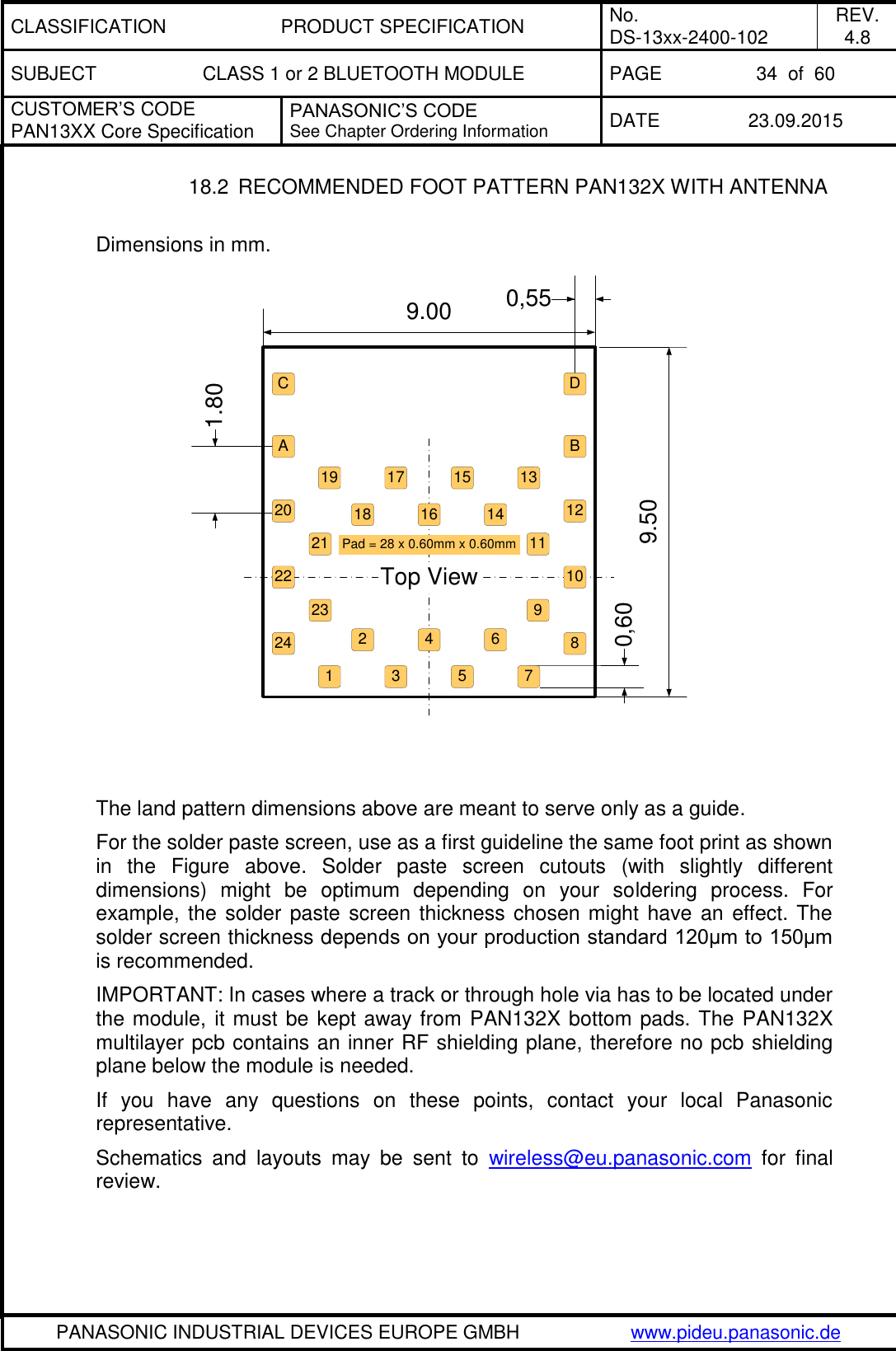
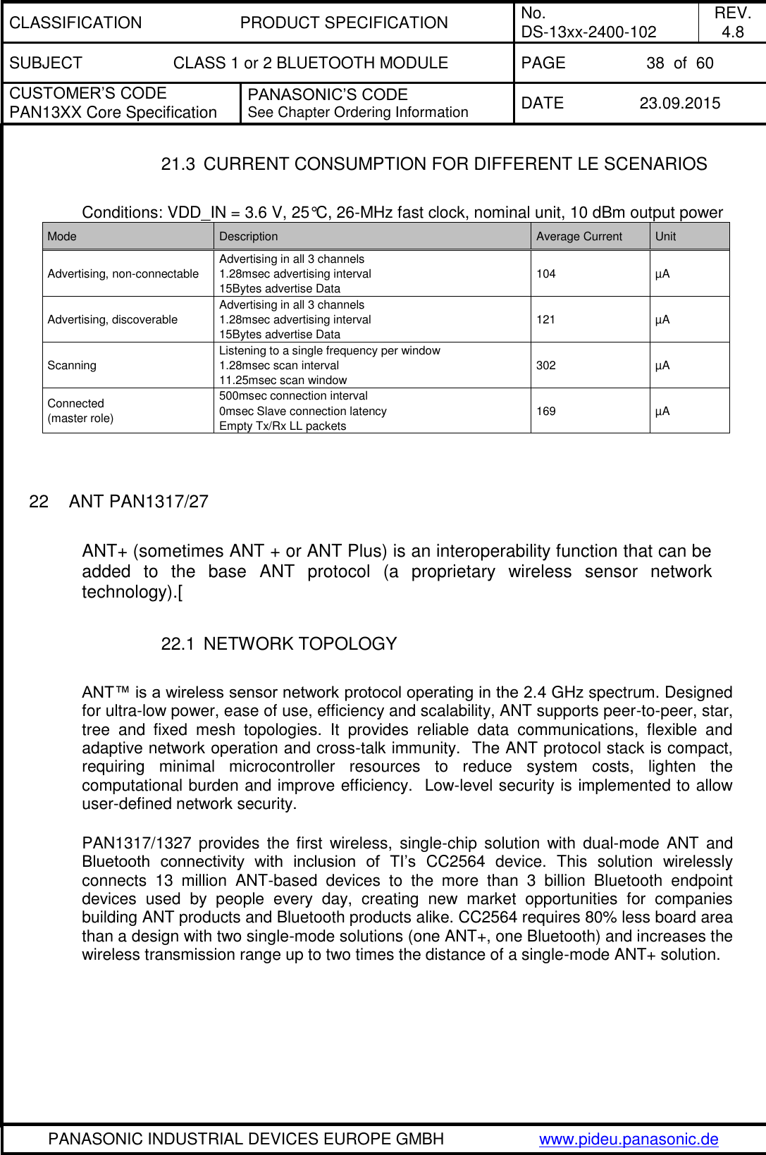
![CLASSIFICATION PRODUCT SPECIFICATION No. DS-13xx-2400-102 REV. 4.8 SUBJECT CLASS 1 or 2 BLUETOOTH MODULE PAGE 23 of 60 CUSTOMER’S CODE PAN13XX Core Specification PANASONIC’S CODE See Chapter Ordering Information DATE 23.09.2015 PANASONIC INDUSTRIAL DEVICES EUROPE GMBH www.pideu.panasonic.de 11.10 CURRENT CONSUMPTION FOR DIFFERENT BLUETOOTH SCENARIOS The following table gives average current consumption for different Bluetooth scenarios. Conditions: VDD_IN = 3.6 V, 25°C, 26-MHz fast clock, nominal unit, 4 dBm output power. 12 BLUETOOTH RF PERFORMANCE No Characteristics Typ BT Spec Max BT Spec Min Class1 Class1 1 Average Power Hopping DH5 [dBm] 22, 23 7.2 20 4 2 Average Power: Ch0 [dBm] 22, 23 7.5 20 4 3 Peak Power: Ch0 [dBm] 22, 23 7.7 23 4 Average Power: Ch39 [dBm] 22, 23 7.0 20 4 5 Peak Power: Ch39 [dBm] 22, 23 7.2 23 6 Average Power: Ch78 [dBm] 22, 23 6.7 20 4 7 Peak Power: Ch78 [dBm] 22, 23 7.0 23 8 Max. Frequency Tolerance: Ch0 [kHz] -2.6 75 -75 9 Max. Frequency Tolerance: Ch39 [kHz] -2.2 75 -75 10 Max. Frequency Tolerance: Ch78 [kHz] -2.1 75 -75 11 Max. Drift: Ch0_DH1 [kHz] 3.6 25 -25 12 Max. Drift: Ch0_DH3 [kHz] 3.7 40 -40 13 Max. Drift: Ch0_DH5 [kHz] 4.0 40 -40 14 Max. Drift Rate: Ch0_DH1 [kHz] -2.6 20 -20 15 Max. Drift Rate: Ch0_DH3 [kHz] -3.2 20 -20 16 Max. Drift Rate: Ch0_DH5 [kHz] -3.3 20 -20 17 Max. Drift: Ch39_DH1 [kHz] 4.0 25 -25 18 Max. Drift: Ch39_DH3 [kHz] 4.3 40 -40 19 Max. Drift: Ch39_DH5 [kHz] 4.3 40 -40 20 Max. Drift Rate: Ch39_DH1 [kHz] -3.1 20 -20 21 Max. Drift Rate: Ch39_DH3 [kHz] -3.6 20 -20](https://usermanual.wiki/Panasonic-Devices-Europe/1315.15-PAN1315-UserMan/User-Guide-2812984-Page-23.png)
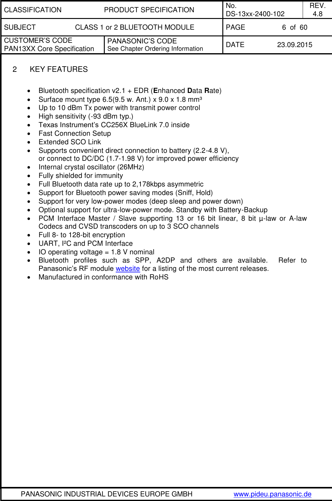
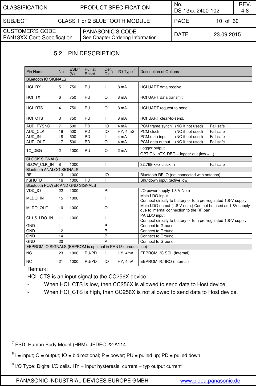
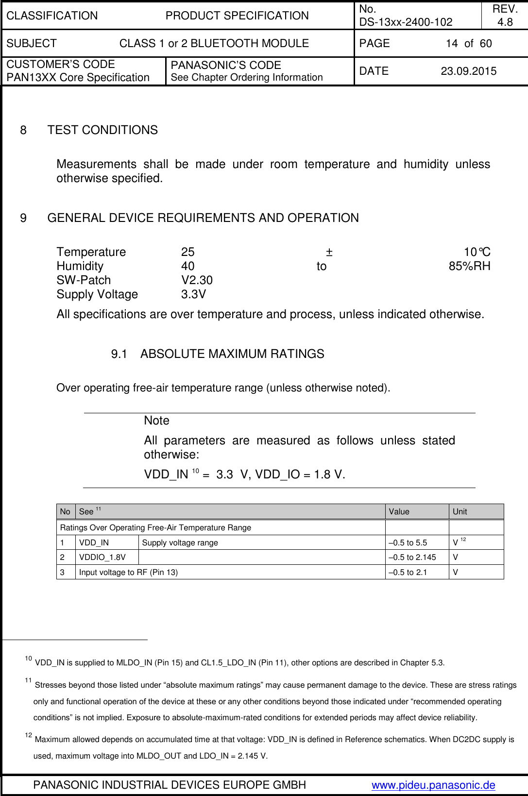
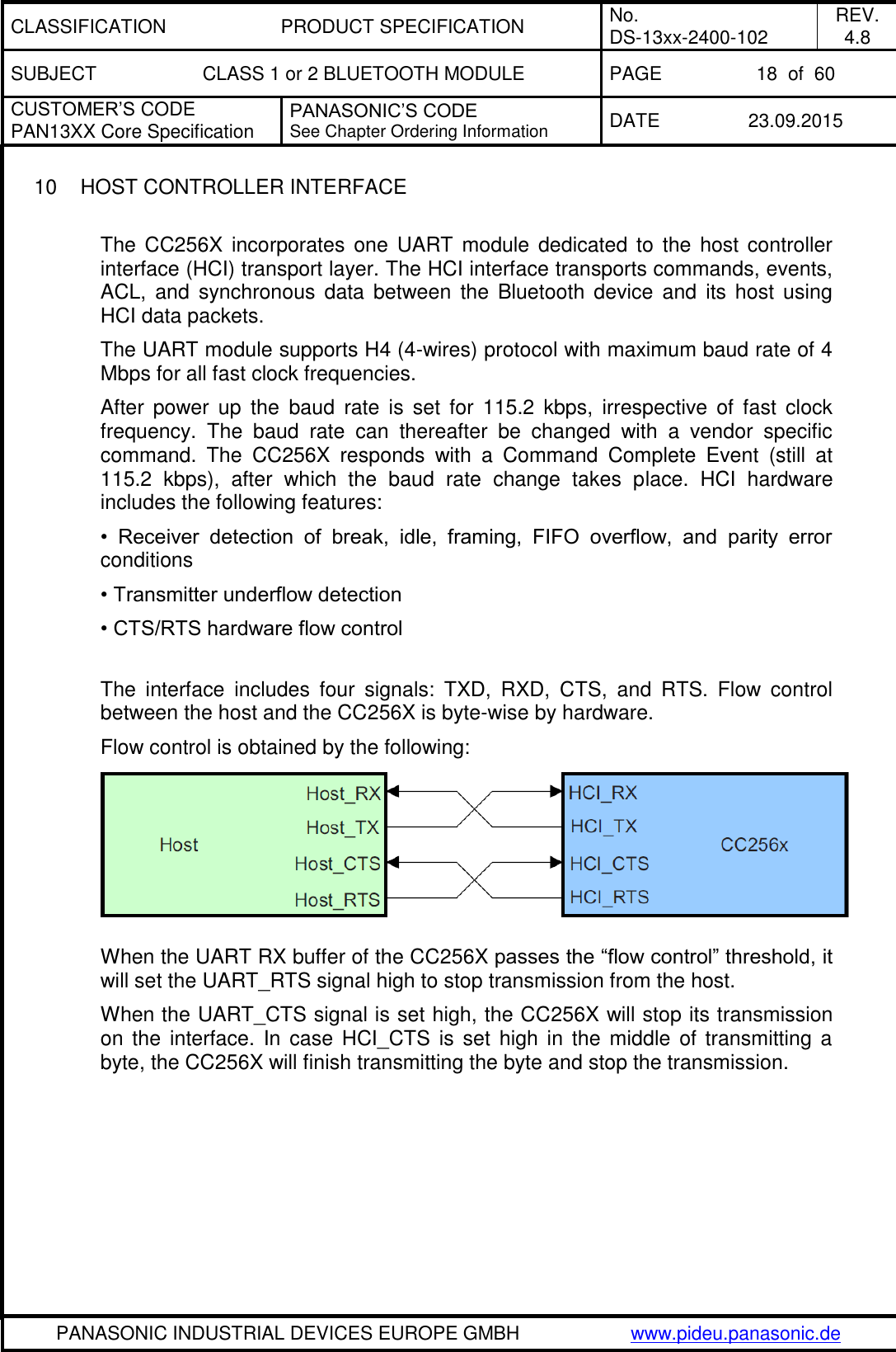
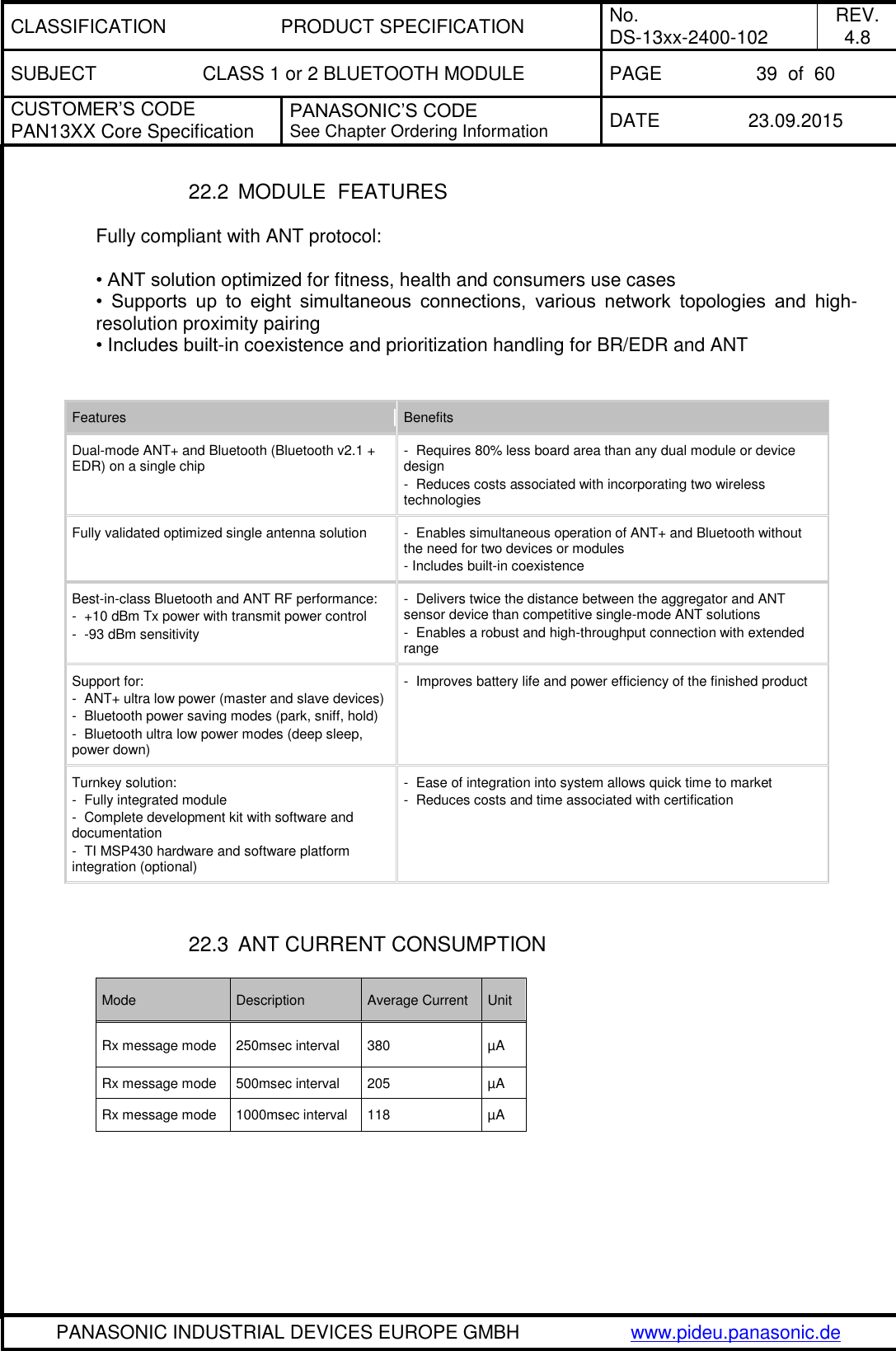
![CLASSIFICATION PRODUCT SPECIFICATION No. DS-13xx-2400-102 REV. 4.8 SUBJECT CLASS 1 or 2 BLUETOOTH MODULE PAGE 24 of 60 CUSTOMER’S CODE PAN13XX Core Specification PANASONIC’S CODE See Chapter Ordering Information DATE 23.09.2015 PANASONIC INDUSTRIAL DEVICES EUROPE GMBH www.pideu.panasonic.de No Characteristics Typ BT Spec Max BT Spec Min Class1 Class1 22 Max. Drift Rate: Ch39_DH5 [kHz] -3.7 20 -20 23 Max. Drift: Ch78_DH1 [kHz] 4.1 25 -25 24 Max. Drift: Ch78_DH3 [kHz] 4.5 40 -40 25 Max. Drift: Ch78_DH5 [kHz] 4.4 40 -40 26 Max. Drift Rate: Ch78_DH1 [kHz] -3.4 20 -20 27 Max. Drift Rate: Ch78_DH3 [kHz] -3.9 20 -20 28 Max. Drift Rate: Ch78_DH5 [kHz] -4.1 20 -20 29 Delta F1 Avg: Ch0 [kHz] 159.5 175 140 30 Delta F2 Max.: Ch0 [%] 100.0 99.9 31 Delta F2 Avg/Delta F1 Avg: Ch0 0.9 0.8 32 Delta F1 Avg: Ch39 [kHz] 159.8 175 140 33 Delta F2 Max.: Ch39 [%] 100.0 99.9 34 Delta F2 Avg/Delta F1 Avg: Ch39 0.9 0.8 35 Delta F1 Avg: Ch78 [kHz] 159.1 175 140 36 Delta F2 Max.: Ch78 [%] 100.0 99.9 37 Delta F2 Avg/Delta F1 Avg: Ch78 0.9 0.8 45 Sensitivity -93.0 -81 46 f(H)-f(L): Ch0 [kHz] 918.4 1000 47 f(H)-f(L): Ch39 [kHz] 918.3 1000 48 f(H)-f(L): Ch78 [kHz] 918.2 1000 49 ACPower -3: Ch3 [dBm] -51.5 -40 50 ACPower -2: Ch3 [dBm] -50.4 -40 51 ACPower -1: Ch3 [dBm] -18.5 52 ACPower Center: Ch3 [dBm] 8.1 20 4 53 ACPower +1: Ch3 [dBm] -19.2 54 ACPower +2: Ch3 [dBm] -50.7 -40 55 ACPower +3: Ch3 [dBm] -53.3 -40 56 ACPower -3: Ch39 [dBm] -51.6 -40 57 ACPower -2: Ch39 [dBm] -50.7 -40 58 ACPower -1: Ch39 [dBm] -19.0 59 ACPower Center: Ch39 [dBm] 7.7 20 4 60 ACPower +1: Ch39 [dBm] -19.7 61 ACPower +2: Ch39 [dBm] -50.9 -40 62 ACPower +3: Ch39 [dBm] -53.2 -40 63 ACPower -3: Ch75 [dBm] -51.7 -40 64 ACPower -2: Ch75 [dBm] -50.7 -40 65 ACPower -1: Ch75 [dBm] -19.2 66 ACPower Center: Ch75 [dBm] 7.5 20 4 67 ACPower +1: Ch75 [dBm] -20.0 68 ACPower +2: Ch75 [dBm] -51.0 -40 69 ACPower +3: Ch75 [dBm] -53.4 -40 70 omega i 2-DH5: Ch0 [kHz] -4.7 75 -75 71 omega o + omega i 2-DH5: Ch0 [kHz] -6.0 75 -75 72 omega o 2-DH5: Ch0 [kHz] -1.5 10 -10 73 DEVM RMS 2-DH5: Ch0 [%] 0.0 0.2](https://usermanual.wiki/Panasonic-Devices-Europe/1315.15-PAN1315-UserMan/User-Guide-2812984-Page-24.png)
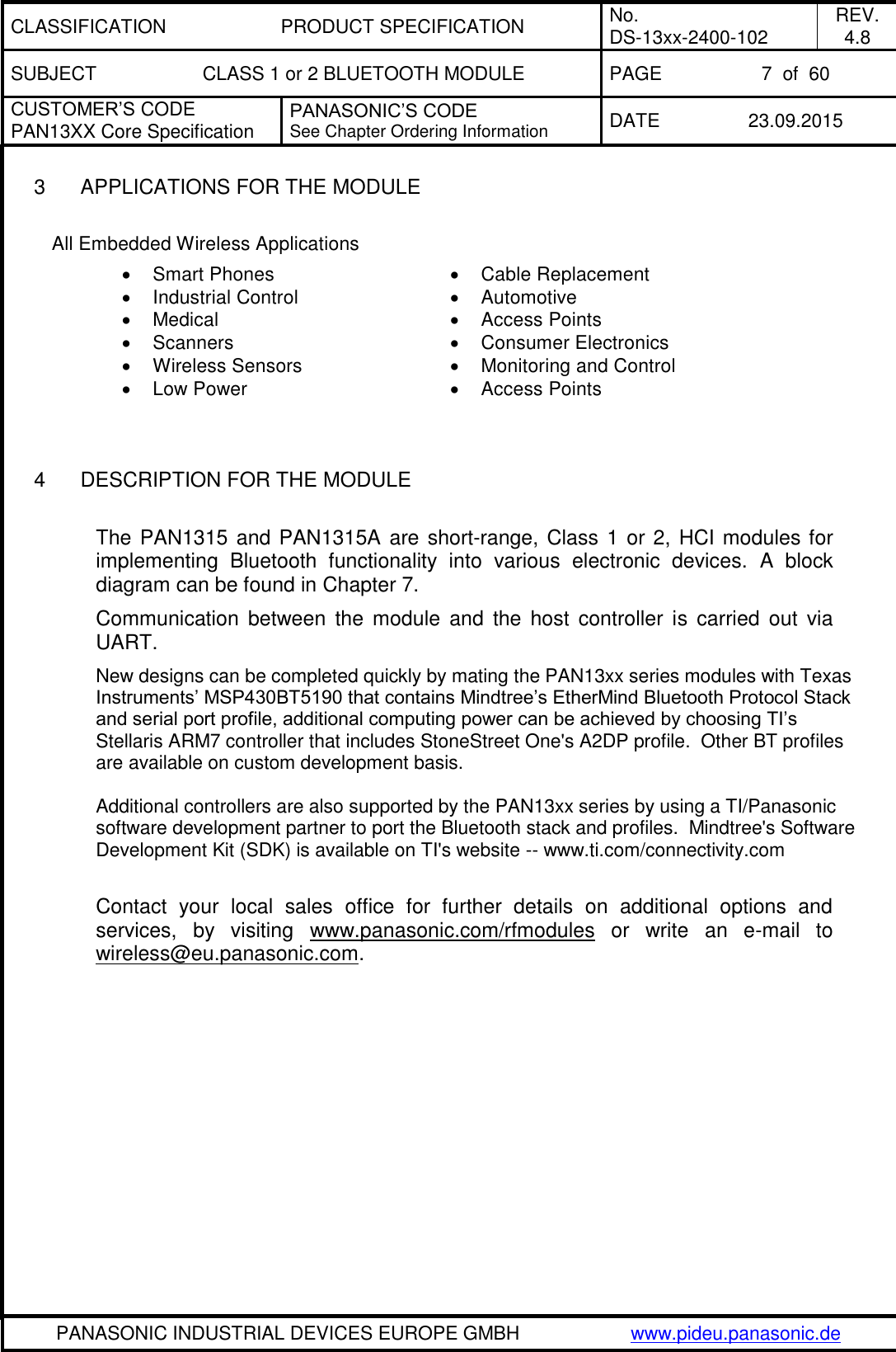
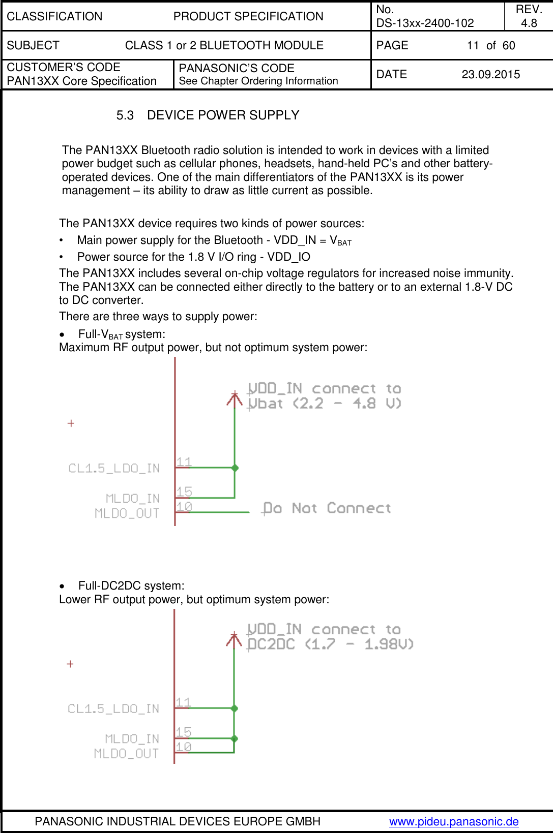
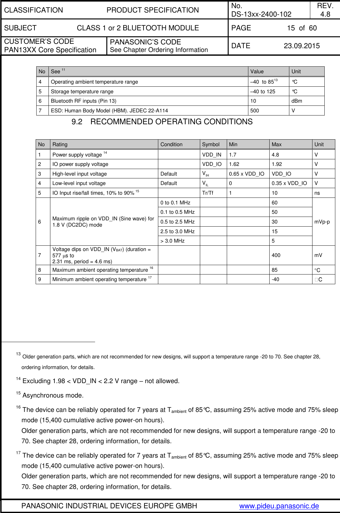
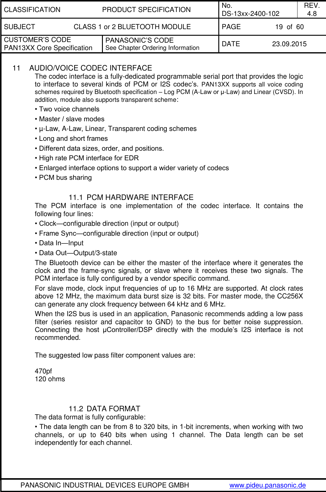
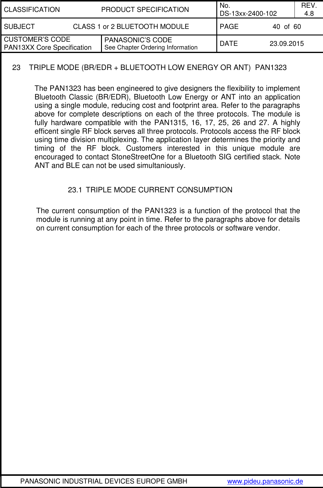
![CLASSIFICATION PRODUCT SPECIFICATION No. DS-13xx-2400-102 REV. 4.8 SUBJECT CLASS 1 or 2 BLUETOOTH MODULE PAGE 25 of 60 CUSTOMER’S CODE PAN13XX Core Specification PANASONIC’S CODE See Chapter Ordering Information DATE 23.09.2015 PANASONIC INDUSTRIAL DEVICES EUROPE GMBH www.pideu.panasonic.de No Characteristics Typ BT Spec Max BT Spec Min Class1 Class1 74 DEVM Peak 2-DH5: Ch0 [%] 0.1 0.35 75 DEVM 99% 2-DH5: Ch0 [%] 100.0 99 76 omega i 3-DH5: Ch0 [kHz] -3.7 75 -75 77 omega o + omega i 3-DH5: Ch0 [kHz] -5.8 75 -75 78 omega o 3-DH5: Ch0 [kHz] -2.6 10 -10 79 DEVM RMS 3-DH5: Ch0 [%] 0.0 0.13 80 DEVM Peak 3-DH5: Ch0 [%] 0.1 0.25 81 DEVM 99% 3-DH5: Ch0 [%] 100.0 99 82 omega i 2-DH5: Ch39 [kHz] -4.8 75 -75 83 omega o + omega i 2-DH5: Ch39 [kHz] -6.1 75 -75 84 omega o 2-DH5: Ch39 [kHz] -1.4 10 -10 85 DEVM RMS 2-DH5: Ch39 [%] 0.0 0.2 86 DEVM Peak 2-DH5: Ch39 [%] 0.1 0.35 87 DEVM 99% 2-DH5: Ch39 [%] 100.0 99 88 omega i 3-DH5: Ch39 [kHz] -3.8 75 -75 89 omega o + omega i 3-DH5: Ch39 [kHz] -5.9 75 -75 90 omega o 3-DH5: Ch39 [kHz] -2.6 10 -10 91 DEVM RMS 3-DH5: Ch39 [%] 0.0 0.13 92 DEVM Peak 3-DH5: Ch39 [%] 0.1 0.25 93 DEVM 99% 3-DH5: Ch39 [%] 100.0 99 94 omega i 2-DH5: Ch78 [kHz] -4.9 75 -75 95 omega o + omega i 2-DH5: Ch78 [kHz] -6.2 75 -75 96 omega o 2-DH5: Ch78 [kHz] -1.4 10 -10 97 DEVM RMS 2-DH5: Ch78 [%] 0.0 0.2 98 DEVM Peak 2-DH5: Ch78 [%] 0.1 0.35 99 DEVM 99% 2-DH5: Ch78 [%] 100.0 99 100 omega i 3-DH5: Ch78 [kHz] -3.8 75 -75 101 omega o + omega i 3-DH5: Ch78 [kHz] -6.0 75 -75 102 omega o 3-DH5: Ch78 [kHz] -2.7 10 -10 103 DEVM RMS 3-DH5: Ch78 [%] 0.0 0.13 104 DEVM Peak 3-DH5: Ch78 [%] 0.1 0.25 105 DEVM 99% 3-DH5: Ch78 [%] 100.0 99 No Characteristics Condition Min Typ Max BT Spec Unit 1 Operation frequency range 2402 2480 MHz 2 Channel spacing 1 MHz 3 Input impedance 50 4 Sensitivity, Dirty Tx on GFSK, BER = 0.1% -93.0 -70 dBm Pi/4-DQPSK, BER = 0.01% -92.5 -70 8DPSK, BER = 0.01% -85.5 -70](https://usermanual.wiki/Panasonic-Devices-Europe/1315.15-PAN1315-UserMan/User-Guide-2812984-Page-25.png)
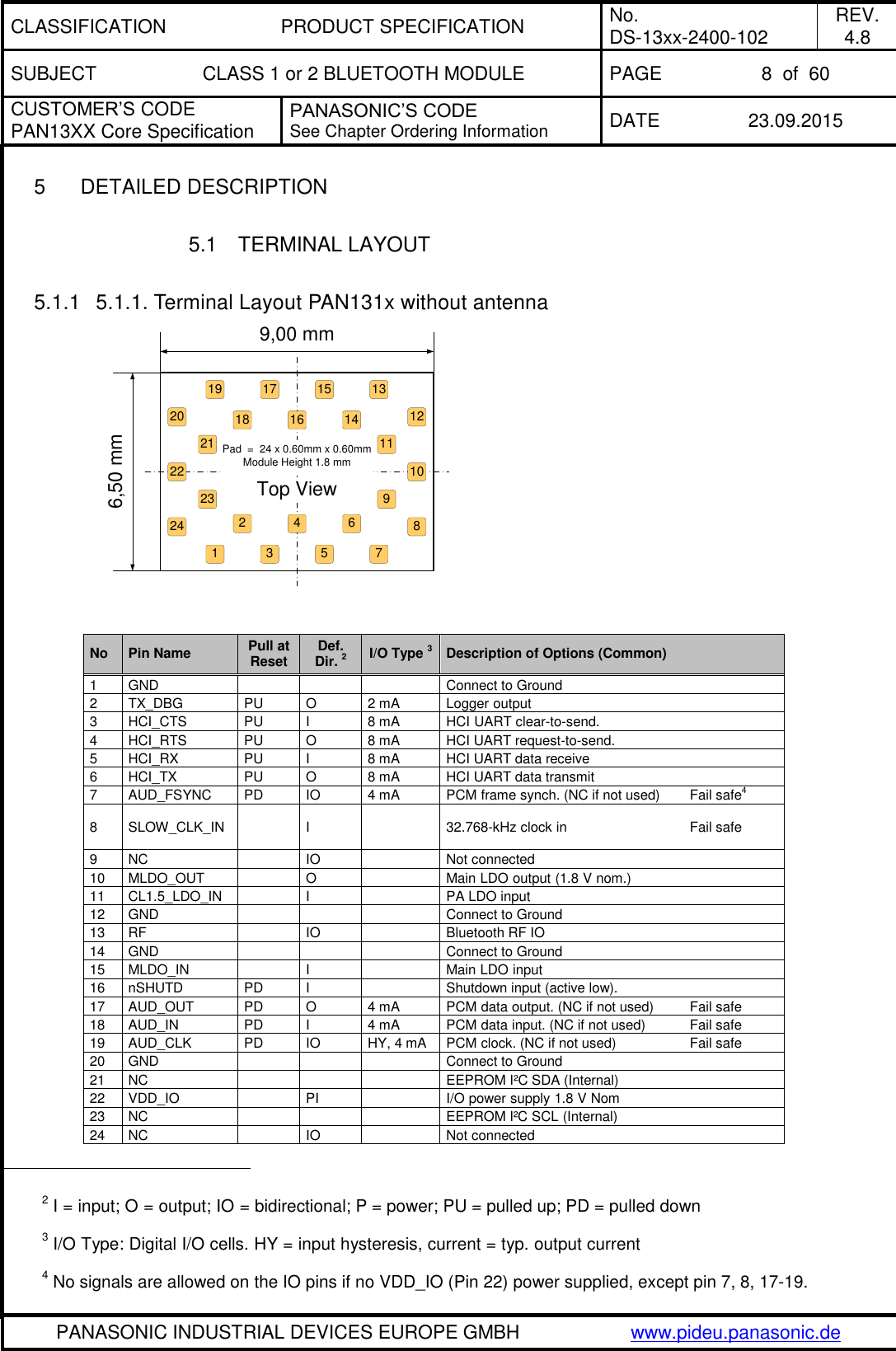
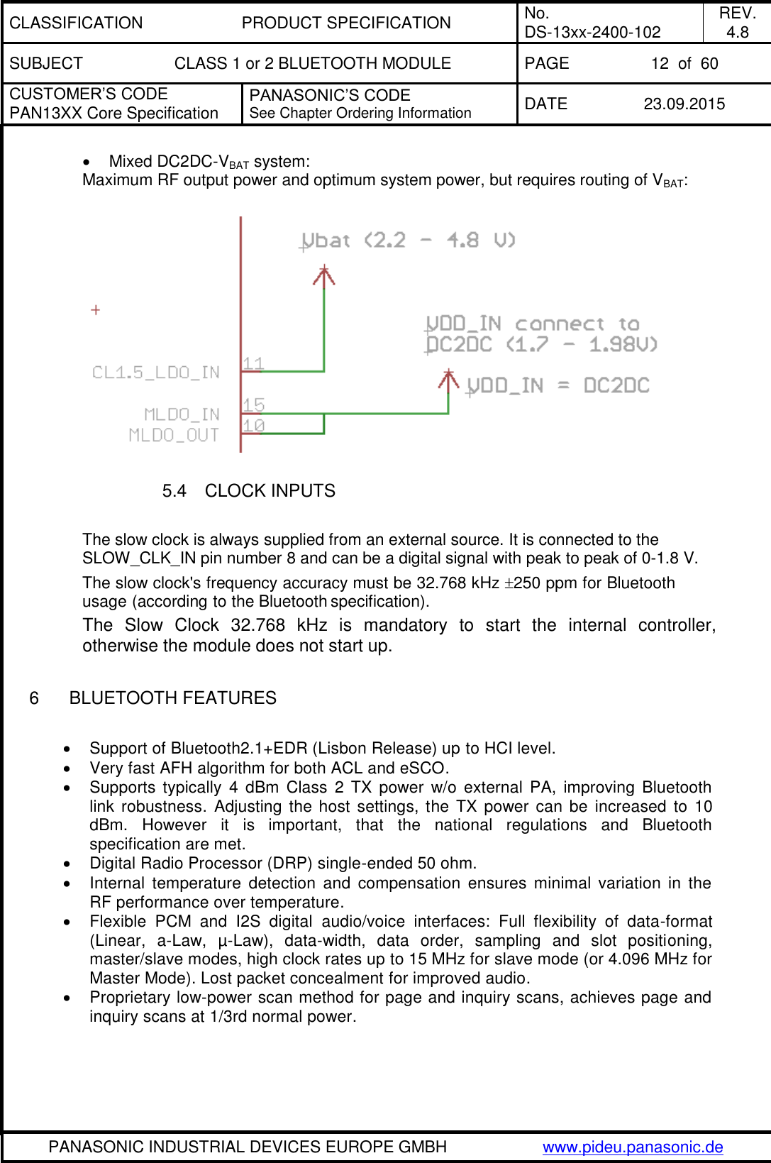
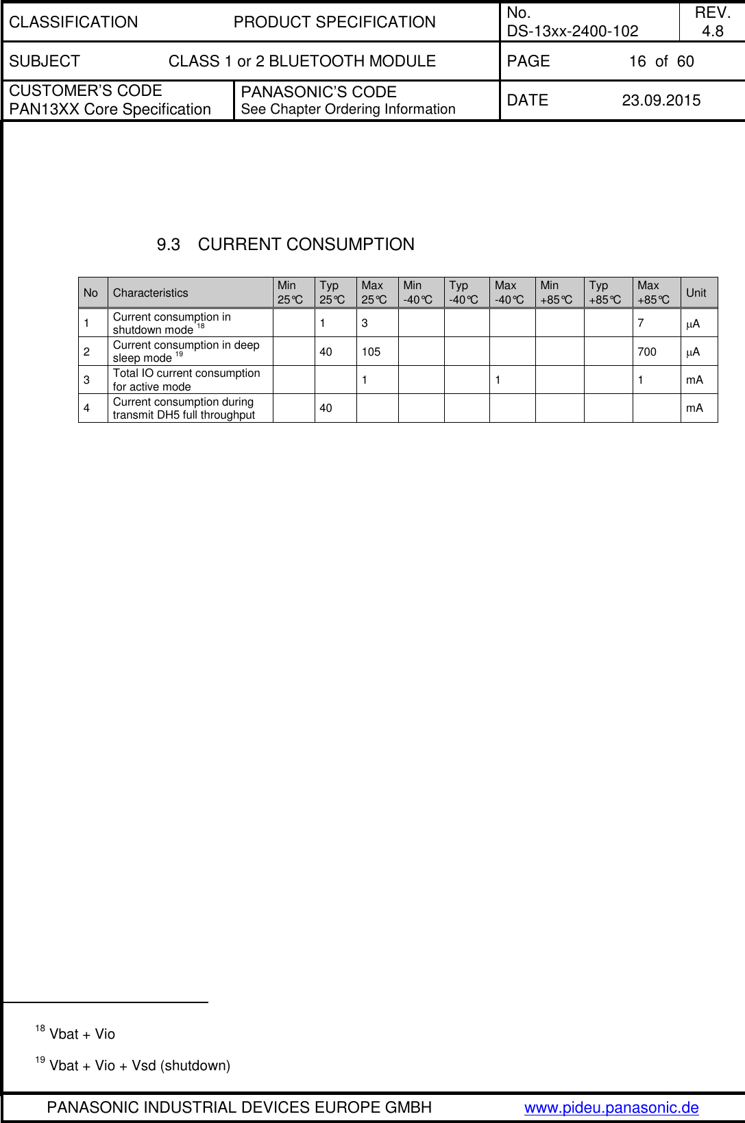
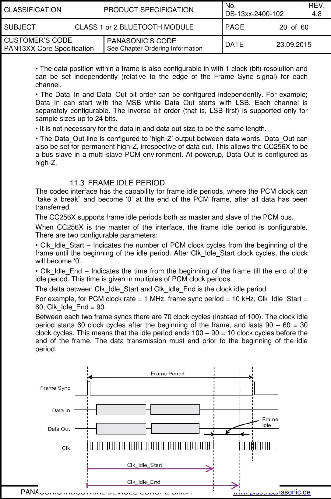
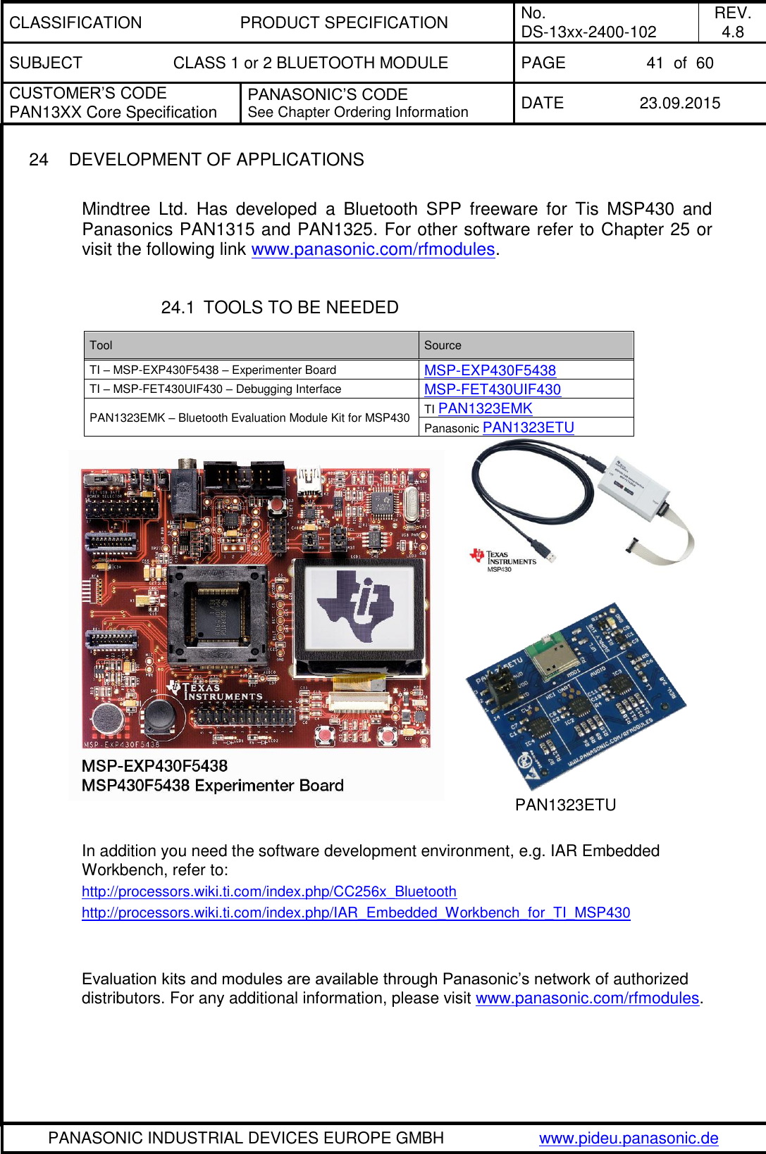
![CLASSIFICATION PRODUCT SPECIFICATION No. DS-13xx-2400-102 REV. 4.8 SUBJECT CLASS 1 or 2 BLUETOOTH MODULE PAGE 26 of 60 CUSTOMER’S CODE PAN13XX Core Specification PANASONIC’S CODE See Chapter Ordering Information DATE 23.09.2015 PANASONIC INDUSTRIAL DEVICES EUROPE GMBH www.pideu.panasonic.de No Characteristics Condition Typ Max Unit 1 Tx and Rx out-of-band emissions Output signal = 7dBm 30 kHz to 1 GHz 21, 22, 23 -30 dBm 1 to 12.75 GHz 21, 22, 23 -30 2 2nd harmonic at 7dBm output power 21, 22, 23 -30 dBm 3 3rd harmonic at 7dBm output power 21, 22, 23 -30 dBm The values are measured conducted. Better suppression of the spurious emissions with an antenna can be expected as, antenna frequently have band pass filter characteristics. 13 SOLDERING TEMPERATURE-TIME PROFILE (FOR REFLOW SOLDERING) 13.1 FOR LEAD SOLDER Recommended temp. profile for reflow soldering Temp.[°C] Time [s] 235°C max. 220 5°C 200°C 150 10°C 90 30s 10 1s 30 +20/-10s 21 Includes effects of frequency hopping 22 Average according FCC, IC and ETSI requirements. Above +7dBm output power (refer also to 23) the customer has to verify the final product against national regulations. 23 +7dBm related to power register value 18, according to TI service pack 2.30](https://usermanual.wiki/Panasonic-Devices-Europe/1315.15-PAN1315-UserMan/User-Guide-2812984-Page-26.png)
![CLASSIFICATION PRODUCT SPECIFICATION No. DS-13xx-2400-102 REV. 4.8 SUBJECT CLASS 1 or 2 BLUETOOTH MODULE PAGE 27 of 60 CUSTOMER’S CODE PAN13XX Core Specification PANASONIC’S CODE See Chapter Ordering Information DATE 23.09.2015 PANASONIC INDUSTRIAL DEVICES EUROPE GMBH www.pideu.panasonic.de 13.2 FOR LEADFREE SOLDER Our used temp. profile for reflow soldering Temp.[°C] Time [s] 230°C -250°C max. 220°C 150°C – 190°C 90 30s 30 +20/-10s Reflow permissible cycle: 2 Opposite side reflow is prohibited due to module weight.](https://usermanual.wiki/Panasonic-Devices-Europe/1315.15-PAN1315-UserMan/User-Guide-2812984-Page-27.png)
![CLASSIFICATION PRODUCT SPECIFICATION No. DS-13xx-2400-102 REV. 4.8 SUBJECT CLASS 1 or 2 BLUETOOTH MODULE PAGE 48 of 60 CUSTOMER’S CODE PAN13XX Core Specification PANASONIC’S CODE See Chapter Ordering Information DATE 23.09.2015 PANASONIC INDUSTRIAL DEVICES EUROPE GMBH www.pideu.panasonic.de Label for Package PAN1315Customer Code ENW89818C2JF105 mm51 mm (1T) Lotcode [YYWWDLL] Example from above: YY year printed 08 WW normal calendar week printed 01 D day printed 5 (Friday) L line identifier, if more as one printed 1 L lot identifier per day printed 1 (1P) Customer Order Code, if any, otherwise company name will be printed (2P) Panasonic Order Code refer to chapter 29 Ordering Information (9D) Datecode as [YYWW] (Q) Quantity [XXXX], variable max. 1500 (HW/SW) Hardware /Software Release Total Package barcodelabelmoisture-sensitive print(already exist on barrier bag) barcodelabeldesiccant 1) 2)moisture indicatorbarrier bagsealedinner carton boxsize 340 x 340 x 41 mm³1) quantity of desiccant according to calculation2) optional: desiccant placed into the corner of the barrier bag](https://usermanual.wiki/Panasonic-Devices-Europe/1315.15-PAN1315-UserMan/User-Guide-2812984-Page-48.png)
![CLASSIFICATION PRODUCT SPECIFICATION No. DS-13xx-2400-102 REV. 4.8 SUBJECT CLASS 1 or 2 BLUETOOTH MODULE PAGE 53 of 60 CUSTOMER’S CODE PAN13XX Core Specification PANASONIC’S CODE See Chapter Ordering Information DATE 23.09.2015 PANASONIC INDUSTRIAL DEVICES EUROPE GMBH www.pideu.panasonic.de 32 RELATED DOCUMENTS For an update, search in the suitable homepage. [1] PAN1323ETU Design-Guide: http://www.panasonic.com/industrial/includes/pdf/PAN1323ETUDesignGuide.pdf [2] CC2560 Product Bulletin: http://focus.ti.com/pdfs/wtbu/cc2560_slyt377.pdf [3] Bluetooth SW for MSP430 is supported by IAR IDE service pack 5.10.6 and later. Use full IAR version edition (not the kick-start version). You can find info on IAR at http://www.iar.com/website1/1.0.1.0/3/1/ and www.MSP430.com . Note, that there is an option for a 30-day free version of IAR evaluation edition. [4] PAN13xx CAD data: http://www.pedeu.panasonic.de/pdf/174ext.zip [5] To aide in the implementation of this reference design, Eagle formatted application and layout files are available on the web at the address below. [6] www.panasonic.com/industrial/includes/pdf/PAN1323ETU_Eagle_Ver1_1.zip [7] Application Note Land Grid Array: http://www.pedeu.panasonic.de/pdf/184ext.pdf](https://usermanual.wiki/Panasonic-Devices-Europe/1315.15-PAN1315-UserMan/User-Guide-2812984-Page-53.png)
![CLASSIFICATION PRODUCT SPECIFICATION No. DS-13xx-2400-102 REV. 4.8 SUBJECT CLASS 1 or 2 BLUETOOTH MODULE PAGE 60 of 60 CUSTOMER’S CODE PAN13XX Core Specification PANASONIC’S CODE See Chapter Ordering Information DATE 23.09.2015 PANASONIC INDUSTRIAL DEVICES EUROPE GMBH www.pideu.panasonic.de As a result of the conformity assessment procedure described in Annex III of the Directive 1999/5/EC, the end-customer equipment should be labelled as follows: PAN13xx and their versions in the specified reference design can be used in the following countries: Austria, Belgium, Cyprus, Czech Republic, Denmark, Estonia, Finland, France, Germany, Greece, Hungary, Ireland, Italy, Latvia, Lithuania, Luxembourg, Malta, Poland, Portugal, Slovakia, Slovenia, Spain, Sweden, The Netherlands, the United Kingdom, Switzerland, and Norway. 34.4 JAPANESE RADIO LAW AND JAPANESE TELECOMMUNICATIONS BUSINESS LAW COMPLIANCE: This device is granted pursuant to the Japanese Radio Law (電波法) and the Japanese Telecommunications Business Law (電気通信事業法) This device should not be modified (otherwise the granted designation number will become invalid) The following models are qualified for Japanese market: ENW89823A2KF MIC ID: [R]202-LSD072 ENW89823A3KF MIC ID: [R]202-LSD072 ENW89829A2KF MIC ID: [R]202-LSD073 ENW89829A3KF MIC ID: [R]202-LSD073 34.5 BLUETOOTH SIG STATEMENT The Design is listed as Controller Subsystem with QDID: B019784 https://www.bluetooth.org/tpg/QLI_viewQDL.cfm?qid=19784 35 LIFE SUPPORT POLICY This Panasonic product is not designed for use in life support appliances, devices, or systems where malfunction can reasonably be expected to result in a significant personal injury to the user, or as a critical component in any life support device or system whose failure to perform can be reasonably expected to cause the failure of the life support device or system, or to affect its safety or effectiveness. Panasonic customers using or selling these products for use in such applications do so at their own risk and agree to fully indemnify Panasonic for any damages resulting.](https://usermanual.wiki/Panasonic-Devices-Europe/1315.15-PAN1315-UserMan/User-Guide-2812984-Page-60.png)