Panasonic Devices Europe 1315 Bluetooth Module User Manual TABLE OF CONTENTS
Panasonic Industrial Devices Europe GmbH Bluetooth Module TABLE OF CONTENTS
Contents
- 1. UserMan
- 2. Updated OEM instruction for module integration
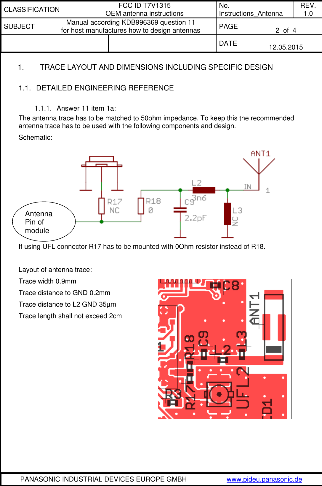
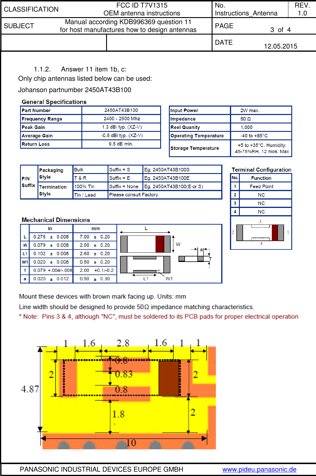
- 3. Updated OEM instruction to design and/or use of antennas KDB 996369 Question 11
- 4. 15_PAN1315 UserMan
Updated OEM instruction to design and/or use of antennas KDB 996369 Question 11