Phottix JUNOTTL Phottix Juno TTL Transceiver Flash User Manual
Phottix (HK) Ltd. Phottix Juno TTL Transceiver Flash
UserManual.wiki
>
Phottix
>
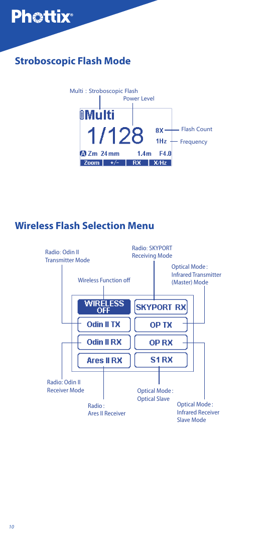
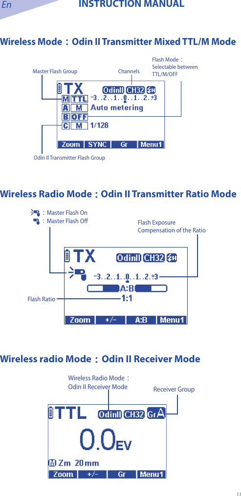
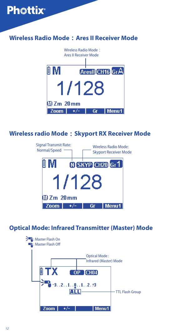
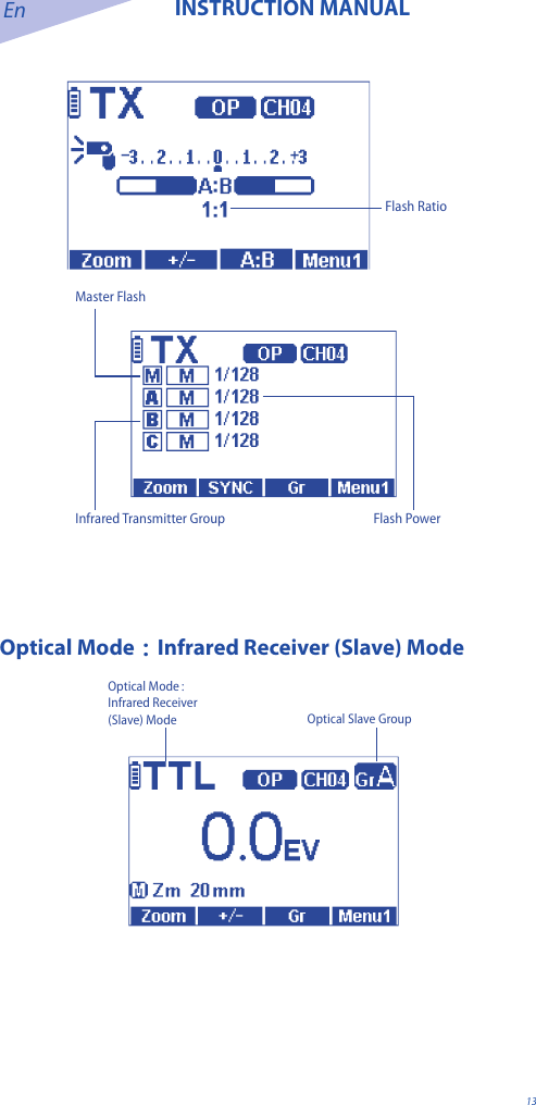
JUNOTTL User Manual
User manual
Navigation menu
Upload a User Manual
Namespaces
Wiki Guide
HTML
PDF
Info
Views
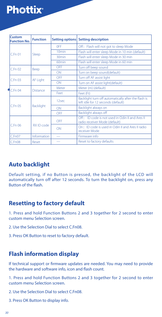
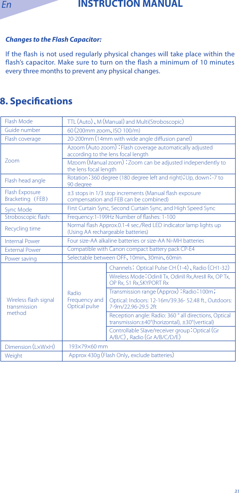
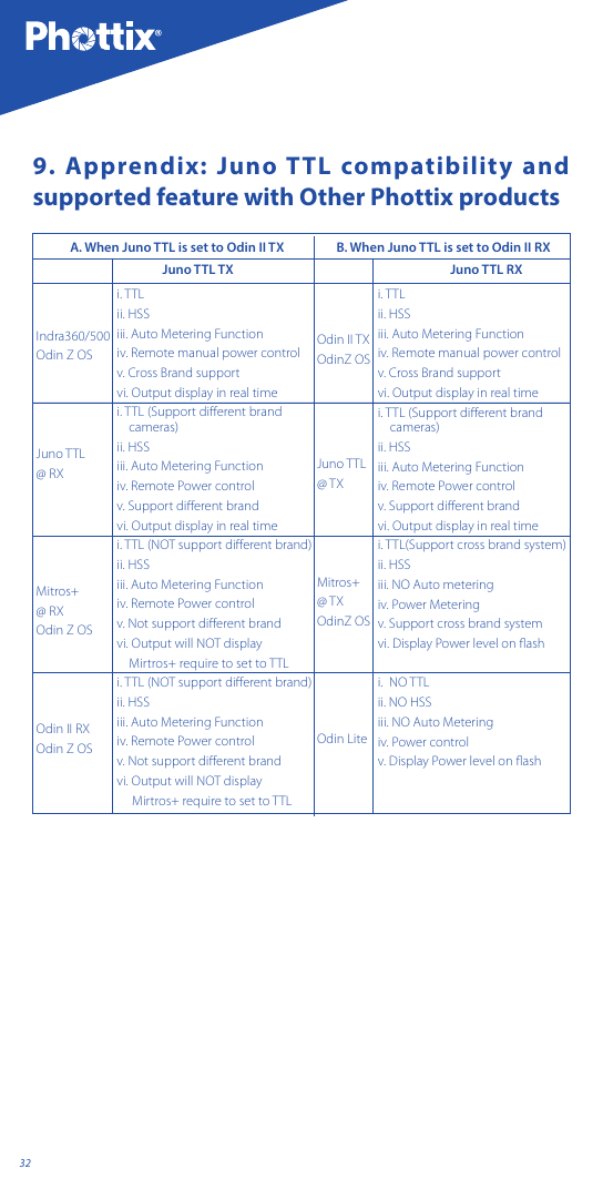
User Manual
Discussion / Help
Navigation