Proxim Wireless S58-B60C Unlicensed Spread Spectrum Transceiver User Manual Backing down from TNG CCI 2
Proxim Wireless Corporation Unlicensed Spread Spectrum Transceiver Backing down from TNG CCI 2
Contents
- 1. Antenna Installation Manual
- 2. Installation Manual 1
- 3. Installation Manual 2
- 4. Installation Manual 3
Antenna Installation Manual

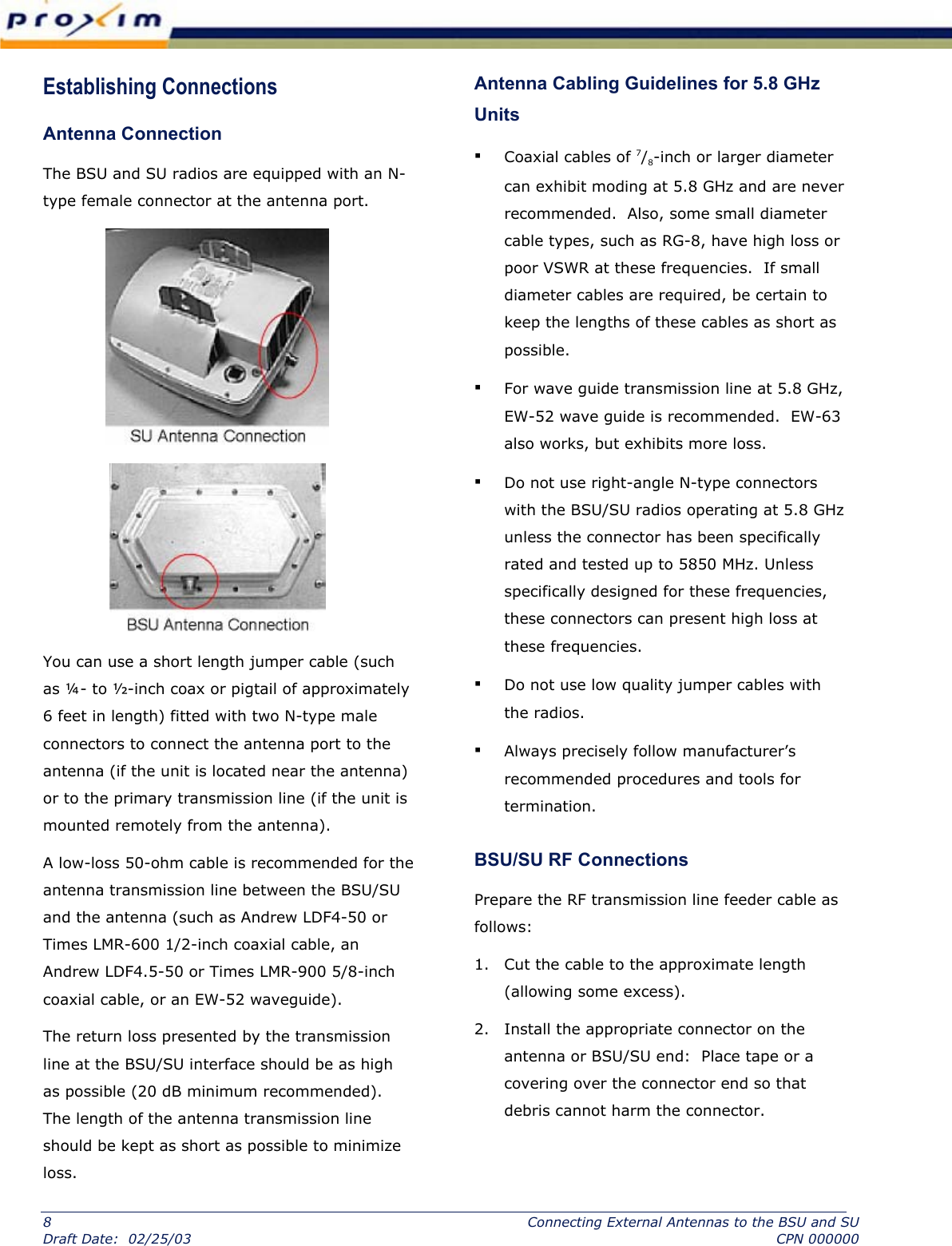
![3. Pull the transmission line through the cable ducts, trays, or conduit (as required) to the antenna, while being careful not to kink or damage the transmission line in any way. Note: RF transmission line must never be bent, twisted, or deformed in any way. Pay close attention to the transmission line specifications for bend radius when installing. 4. Support the transmission line in a tray on horizontal runs and by hangers on vertical runs. Space hangers according to the manufacturer instructions (typically every five feet under conditions of no ice and not greater than 85 mph winds). 5. Ground the transmission line using the manufacturer grounding kit. Grounding kits attach to the outer copper conductor. Install grounds at the antenna, at the bottom of the antenna structure (if applicable), and where the transmission line enters the building. Be sure to ground long transmission line runs every 100 feet. 6. Lightning suppression (such as Polyphaser LSX) is required at the interconnection cable junction as close as possible to the BSU/SU when the cable is longer than 3 meters. There should always be a lightning protection device at the egress point for whatever cables egress the building or enclosure. Lightning arrestors must be properly grounded to operate. 7. After installation, terminate the transmission line with an N-type male connector or adapter attached at the equipment end. For wave guide, this typically requires a CPR-to-N adapter. Be sure to use manufacturer-specified connectors and termination tools, and follow termination instructions precisely. Improper transmission line terminations can cause excess losses and reflections that can lead to many problems with the system. 8. Prior to operation, check the electrical integrity of the transmission line, including all connectors, with a simple DC check between the center conductor and outer conductor (this is neither possible, nor required for wave guide). The transmission line ideally should be connected directly to the antenna at one end and to the BSU/SU antenna port at the other end (through the RF Lightning arrestor). However, short pigtail jumper cables may be required to avoid sharp bends in the primary transmission line to limit stress on either connection. 9. Connect the transmission line to the RF connector on the BSU or SU. Create a drip loop in the cable as shown in the figure below, and tie the cable to the mast or pole to remove any stress on the RF connector. The drip loop allows any moisture on the wires from rain or condensation to drip off. [temporary photo] Connecting External Antennas to the BSU and SU 9 CPN 000000 Draft Date: 02/25/03](https://usermanual.wiki/Proxim-Wireless/S58-B60C.Antenna-Installation-Manual/User-Guide-314520-Page-9.png)