Queclink Wireless Solutions GV300W GPS Locator User Manual
Queclink Wireless Solutions Co.,Ltd GPS Locator
UserManual.wiki
>
Queclink Wireless Solutions
>
GV300W User Manual
User Manual
Navigation menu
Upload a User Manual
Namespaces
Wiki Guide
HTML
PDF
Info
Views
User Manual
Discussion / Help
Navigation
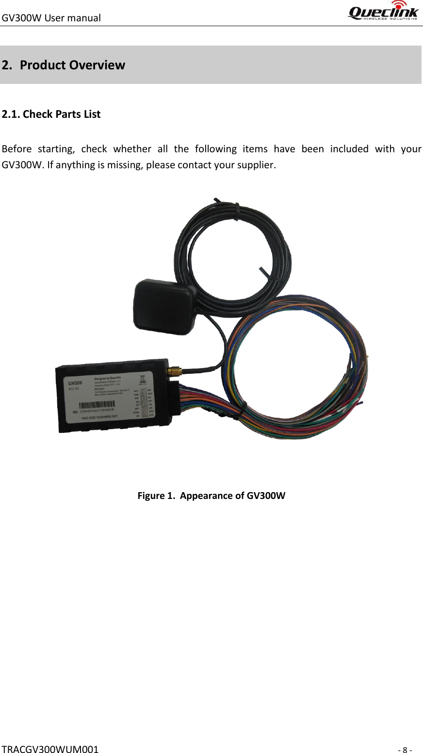
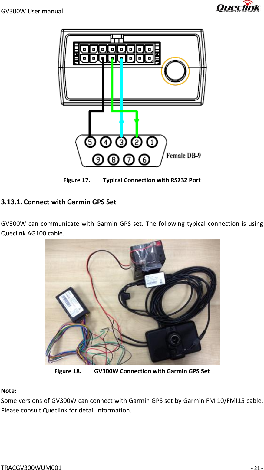
![GV300 User manual TRACGV3SUM001 - 1 - GPS Locator User Manual TRACGV300WUM001 Version:[1.00] GV300W](https://usermanual.wiki/Queclink-Wireless-Solutions/GV300W/User-Guide-2700396-Page-1.png)
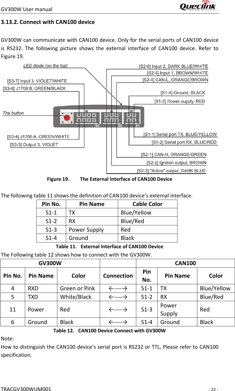
![GV300W User manual TRACGV300WUM001 - 7 - 1. Introduction The GV300W is a compact GNSS tracker designed for a wide variety of vehicle tracking applications. It has multiple I/O interfaces that can be used for monitoring or controlling external devices. Its built-in GNSS receiver has superior sensitivity and fast time to first fix. Its triple band WCDMA subsystem supports UMTS/HSDPA 850 (Band V)/1900 (Band II)/2100(Band I) MHz allowing the GV300W's location to be monitored in real time or periodically tracked by a backend server and mobile devices. Its built-in 3-axis accelerometer allows driving behavior monitoring, motion detection and extended battery life through sophisticated power management algorithms. System integration is straightforward as complete documentation is provided for the full featured @Track protocol. The @Track protocol supports a wide variety of reports including emergency, geo-fence boundary crossings, driving behavior, low battery and scheduled GNSS position. 1.1 Reference Table 1. GV300W Protocol Reference SN Document name Remark [1] GV300W @Track Air Interface Protocol The air protocol interface between GV300W and backend server. 1.2 Terms and Abbreviations Table 2. Terms and Abbreviations Abbreviation Description AGND Analog Ground AIN Analog Input DIN Digital Input DOUT Digital Output GND Ground MIC Microphone RXD Receive Data TXD Transmit Data SPKN Speaker Negative SPKP Speaker Positive](https://usermanual.wiki/Queclink-Wireless-Solutions/GV300W/User-Guide-2700396-Page-7.png)