RF Engineering and Energy Resource KI-GSM904 Water leak host panel User Manual Security GSM Alarm System
RF Engineering & Energy Resource, LLC Water leak host panel Security GSM Alarm System
UserManual.wiki
>
RF Engineering and Energy Resource
>
KI GSM904 User Manual
User manual
Navigation menu
Upload a User Manual
Namespaces
Wiki Guide
HTML
PDF
Info
Views
User Manual
Discussion / Help
Navigation
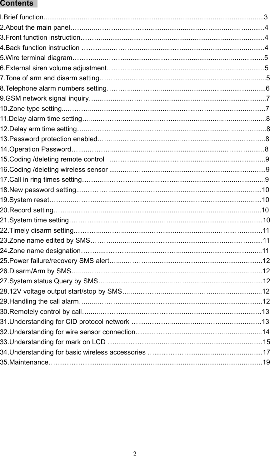
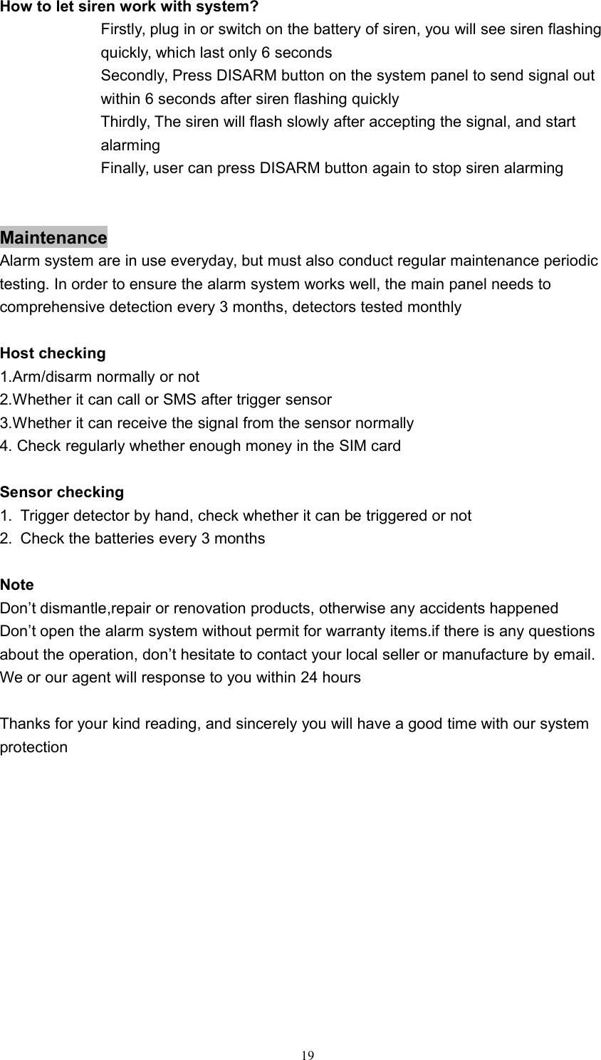
![53. Wire terminal diagramInitializationPlease insert the prepaid SIM card carefully at the back of main panel,and then plug in ACpower.( If you want to recharge the back up battery, you need to switch on firstly and thenplug in AC power)The LCD display will show [F5]→[F6]→[Signal strength ] one by one after you power onthe system. It means the system is connected to GSM network. And the GSM LEDindicator will flash slowly 1 time every 3 secondsSystem settingAll the settings can be carried out under the disarmed status with a long ‘DI’for all the proper operations. while two short sounds for wrong settings1.External siren volume adjustmentUnder the disarm status, User can program the following command to adjustthe volume of siren. The X is bigger, the sound will be bigger too.Finallypress [#] again to end this operation. You will hear a long ‘DI’ sound to showcorrect setting.Command:[#]→[0]→[X]→[#]X=1-9: External siren sound will be bigger for bigger numberX=0: External siren sound will be off2. Human voice on or offUser can close or open the human voice reminder as per your needs.Command:[*]→[0]→[4]→[X]→[*]X=1: Voice will be offX=0: Voice will be on3.Tone of arm and disarm settingThe external siren will give off response tone for each arm and disarmCommand:[*]→[2]→[X]→[*]X=1: Enable siren response for arming and disarmingX=0: Disable siren response for arming and disarming](https://usermanual.wiki/RF-Engineering-and-Energy-Resource/KI-GSM904/User-Guide-3050493-Page-6.png)
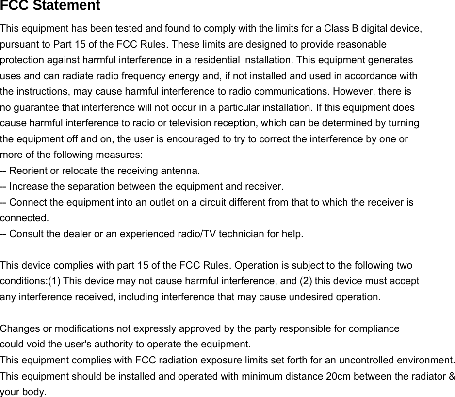
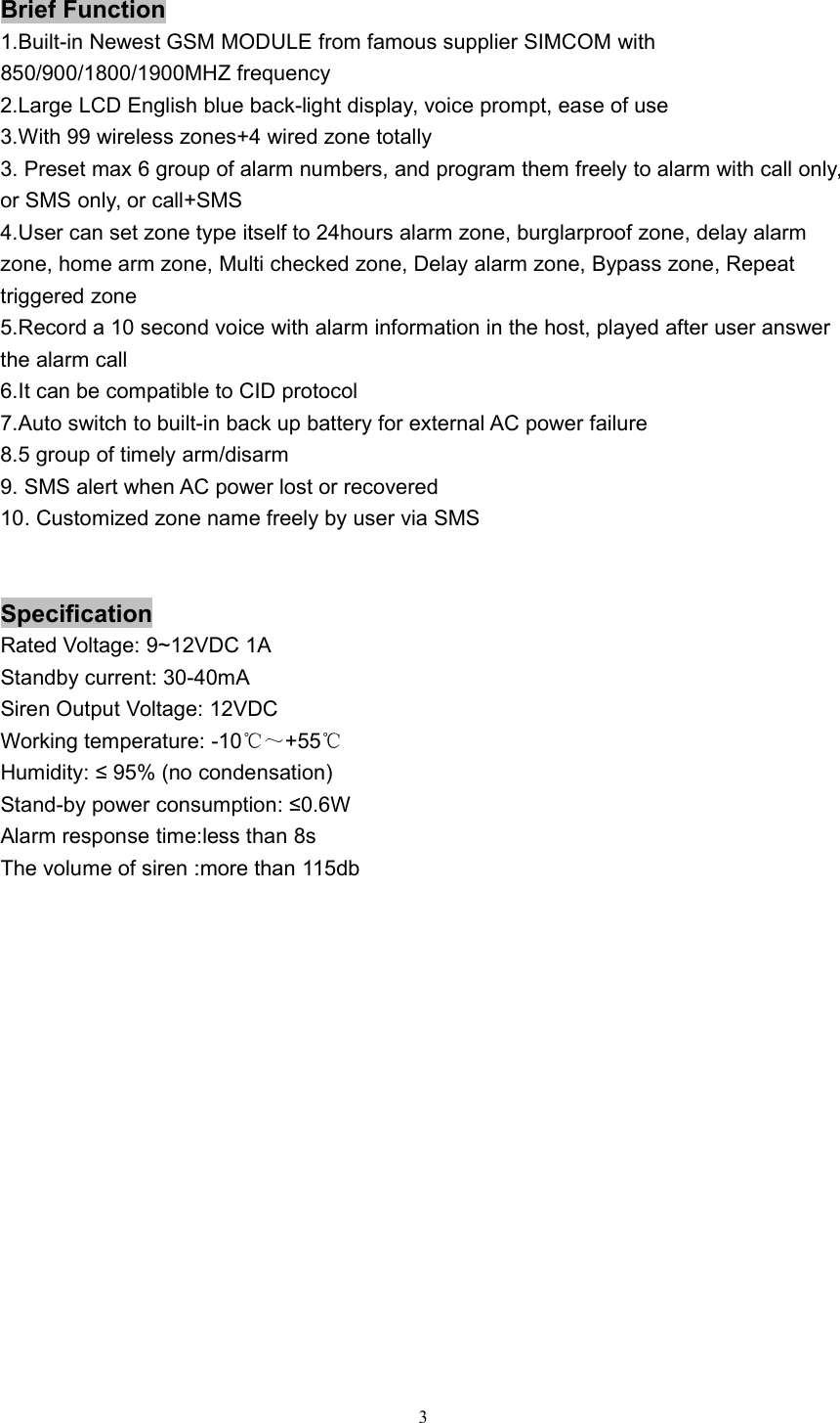
![64.Telephone alarm numbers settingUser can preset max 6 groups of telephone alarm number,which thesystem will auto dial or send SMS to after alarm happenedCommand on the main panel: [#]→[X]→[telephone number]→[#]X=1: The 1st telephone alarm numberX=2: The 2nd telephone alarm numberX=3: The 3rd telephone alarm numberX=4: The 4th telephone alarm numberX=5: The 5th telephone alarm numberX=6: The 6th telephone alarm numberExample: #118200986586# to set 18200986586 as the 1st telephone alarm number5.Telephone alarm numbers type settingUser can set all 6 groups of alarm numbers as SMS alarm, Call alarmor SMS+Call alarm as per requirementCommand:[#]→[X]→[A]→[#]X=(1-6): The series number of 6 group of telephone alarm numbersA=2: Call alarm typeA=3: SMS alarm typeA=4: Call+SMS alarm typeExample: Set the 2nd phone number to SMS alarm type: [#]→[2]→[3]→[#]6.Telephone alarm numbers deletingUser can delete any group of 6 telephone alarm numbersCommand:[#]→[X]→[[#]X=(1-6): The series number of 6 group of telephone alarm numbersExample: Delete the 2nd phone number : [#]→[2]→[#]7.Alarm log inquiryUser can check the total 10 logs by press (0-9) numbers DIRECTLY onthe panel on the disarm statusCommand:[X]X=(0-9), X=0: the latest logX=9: the last logExample: If you want to check the latest log, you can press 0, and found the LED indicatorshowing:](https://usermanual.wiki/RF-Engineering-and-Energy-Resource/KI-GSM904/User-Guide-3050493-Page-7.png)
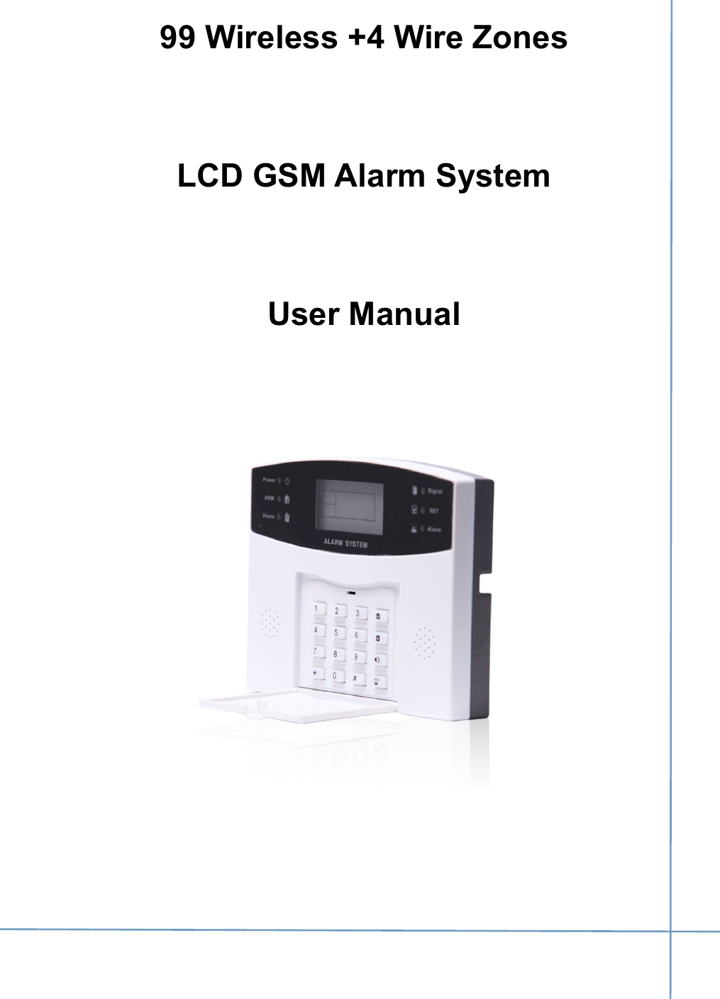
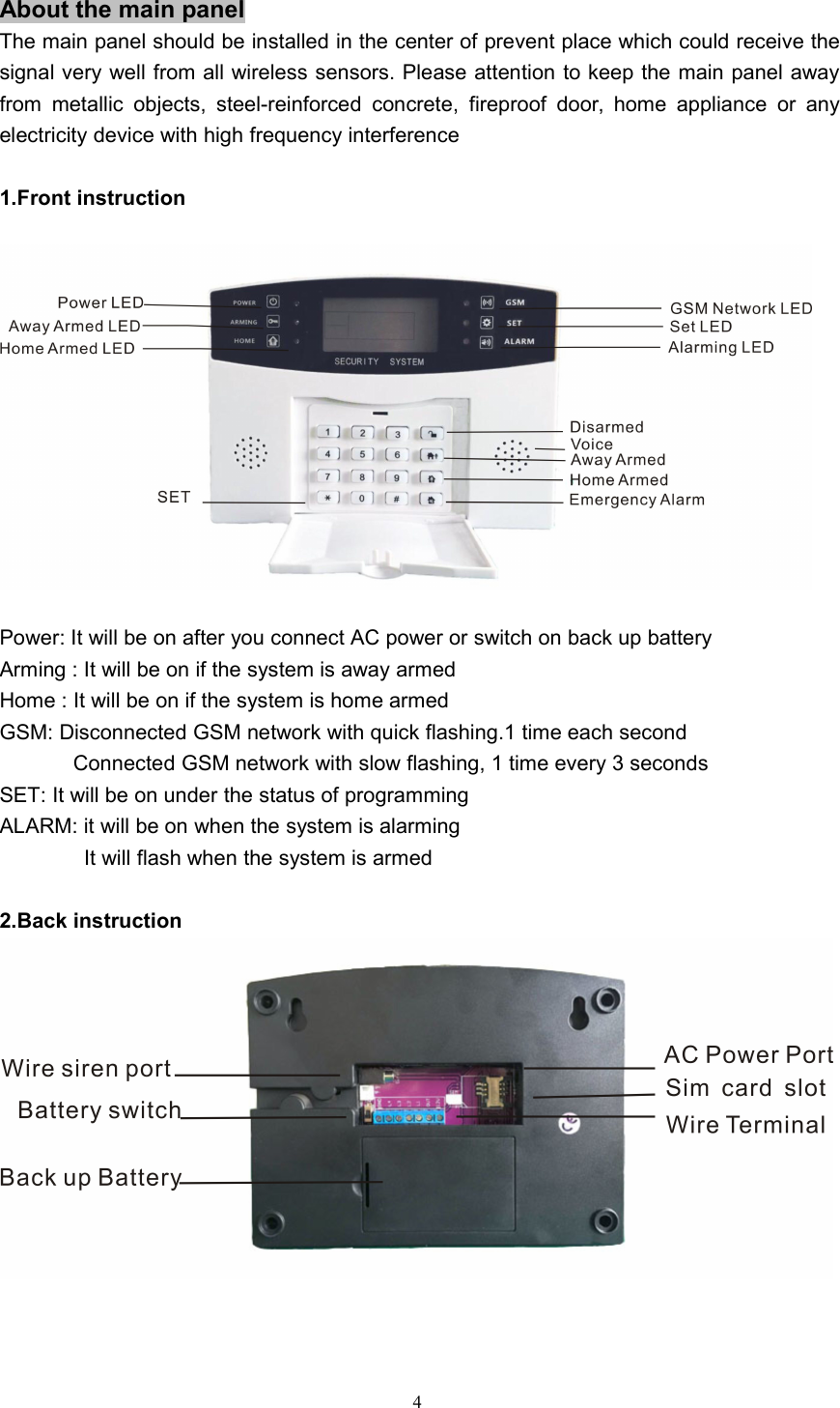
![7It means that the latest log is emergency alarm8. GSM network signal inquiryUser can check the GSM signal before use on the main panel, so that the system cansend alarm information successfully without any delay or missing.Command:[*]→[9]→[4]→[*]You will see the strength number on the LCD. If the number is less than 10, it meanssignal is bad. If the number is more than 30, it means no GSM signal. Bigger numbermeans stronger signal for the numbers between 10 and 309.Zone type settingUser can set all zones with any kind of different zone typeCommand:[#]→[8]→[A]→[B]→[#]A=(1-104): zone numberB=(0-8): 8 kinds of different zone type0: inactive1:burglarproof alarm2:home arm3: emergency alarm4: multi checked5: delay alarm7: double trigger8: doorbellZone number1-9899100101-104Wireless/wire zoneswireless zone 1-wireless zone 98uselessuseless4 wire zone](https://usermanual.wiki/RF-Engineering-and-Energy-Resource/KI-GSM904/User-Guide-3050493-Page-8.png)
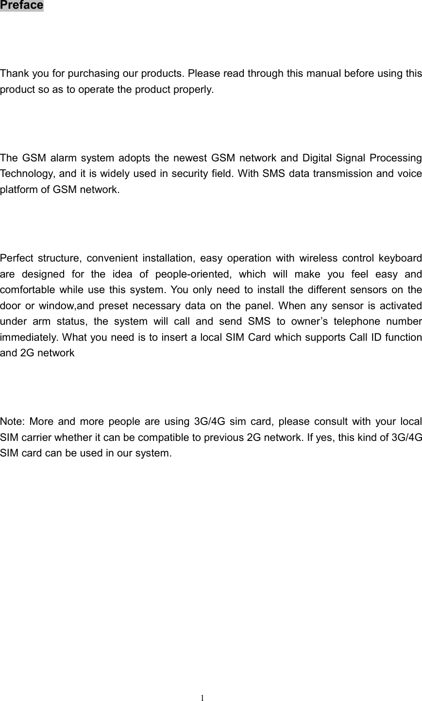
![8Example: If you want to zone 15 to be home alarm type: [#]→[8]→[15]→[2]→[#]Inactive zone: The zone will be closedBurglarproof alarm zone: The sensors will trigger alarm under arming status, but it won’ttrigger Alarm under disarming statusEmergency alarm zone: No matter when the system is armed or disarmed, the sensorsat emergency zone will trigger alarm. Which is mainly for smokesensor, gas sensor, panic button etcHome arm zone: The sensors at home arm zone won’t trigger alarm under the home armstatus, but other sensors will trigger alarm as normalMulti checked zone: Only 2 or more sensors at the same zone are triggered within 30seconds, it will trigger alarmDelay alarm zone: The alarm only be started in the preset delayed time after triggeredDouble trigger zone: It will alarm when the sensor is triggered twice within 5-30 seconds,otherwise it won’t give off alarmDoorbell: It won’t give off alarm but “ding dong” doorbell sound for each trigger10.Delay alarm time settingThe alarm will start after delayed time you setCommand:[#]→[7]→[A]→[#]A=0-99 seconds, max 99 seconds11.Delay arm time settingThe system will be armed automatically after delayed time you set afterpress arm button of remote control or main panelCommand:[*]→[4]→[A]→[#]A=0-99 seconds, max 99 secondsNote: If you press ARM button twice, the system will be armed quickly without delay12.Password protection enabledThe panel will be protected by operation password in 26 seconds onceyou enable this functionCommand: [*]→[1]→[1]→[*]13.Password protection disabledThe panel won’t be protected by operation password once you disablethis functionCommand: [*]→[1]→[0]→[*]14.Operation PasswordThe panel will require user to input password before any operation if userenable the password protectionCommand:[*]→[A]→[*]A=password, 4 digits. The defaulted password is 0000](https://usermanual.wiki/RF-Engineering-and-Energy-Resource/KI-GSM904/User-Guide-3050493-Page-9.png)
![915.Coding /deleting remote controlCoding: User can press the command on the main panel, and trigger the signal out within10 seconds by press any button on the remote control. You will hear along DI sound to show coding successfully and LCD display showing 01.If you want to code second remote control, you can operate with thesame way, and LCD display will show 02 accordinglyCommand: [*]→[0]→[*]Deleting: User can press the command on the main panel, You will hear a long DI soundto show ALL remote control will be deleted successfullyCommand: [*]→[0]→[2]→[*]16.Coding /deleting wireless sensorCoding: User can press the command on the main panel, and send the signal out within10 seconds by trigger the wireless sensor.You will hear a long DI soundto show coding successfully and LCD display showing its zone number. Ifyou want to code more sensors, you can do it with the same way.Command: [*]→[8]→[A]→[*]A= zone number with 2 digits: 01,02,03,.....10......98Example: we need to add 2 wireless door sensor to zone 05, and zone 98. We can do likethis: Press command [*]→[8]→[05]→[*], trigger the first door sensor. You will hear a long‘DI’ sound to show coding successfully. And then press command [*]→[8]→[98]→[*],trigger the second door sensor, you will hear a long ‘DI’ sound tooDeleting: User can press the following command on the main panel, You will hear a long‘DI’ sound to show deleting successfullyCommand: [#]→[8]→[A]→[6]→[#]A= zone number with 2 digits: 01,02,03,.....10......98.Example: we need to delete the wireless door sensor at zone 05. We can do like this:Press command [#]→[8]→[05]→[6]→[#] on the main panel. You will hear a long DI soundto show deleting successfullyNote: If we want to delete all wireless sensors for all zones, we can press command[#]→[8]→[99]→[6]→[#]17.Call in ring times settingThe system will answer the call from user after preset “DU” ring timesCommand:[*]→[6]→[A]→[*]A= digits: 0,1,2,3.......... ; 0 means to disable the call in functionExample: Require system to answer the coming call after 3 “DU” sounds, user can presscommand [*]→[6]→[3]→[*] on the main panel18.Siren alarm time settingUser can set the siren alarming time with 00-30 minutes.Command:[#]→[9]→[A]→[#]A=0-30 minutes](https://usermanual.wiki/RF-Engineering-and-Energy-Resource/KI-GSM904/User-Guide-3050493-Page-10.png)
![1019.New password settingUser can modify the system with new password in the case of forgetting theprevious passwordCommand:[*]→[7]→[A]→[A]→[*]A= new password with 4 digits .The defaulted password is 0000Example: We need to modify the new password to 8585, we can press command[*]→[7]→[8585]→[8585]→[*] on the main panel20.System resetAll data will be cleared, except for coded sensorsCommand:[*]→[8]→[A]→[*]A= password, default password: 0000Example: Press command [*]→[8]→[0000]→[*], the system will be reset21.Record settingUser can record 10 seconds voice to show alarm information includingaddress, telephone number etc, which will be played on the alarm callCommand:[*]→[0]→[A]→[*]A= system passwordExample:Press command [*]→[0]→[0000]→[*] on the main panel firstly, and saysomething within 10 seconds near to panel about 20cm. It will quit automatically whentime’s out22.System time settingBefore installation, user can set the correct time for the system as per thefollowing commandCommand:[*]→[0]→[7]→[A]→[B]→[C]→[D]→[E]→[*]A= Year, 15 means 2015, 16 means 2016B=Month, 01 means Jan, 10 means OctC=Day,11 means 11th ,08 means 08th,D=Hour, 08 means 8 o’clock, 09 means 9 o’clockE=Minute, 05 means 5 minute, 20 means 20 minuteExample, Set system time to 2016 years at 12:25 on Oct 13th, user can press thecommand [*]→[0]→[7]→[16]→[10]→[13]→[12]→[25]→[*]Note: The system time will be clear if the system was off, so please switch on the batteryfor system in case of ac power failure23.Timely arm settingSystem supports max 5 groups of timely arm, it will be armed automaticallyeveryday as per the timeCommand: [#]→[0]→[7]→[A]→[B]→[C]→[#]A=Hour, 08 means 8 o’clock, 09 means 9 o’clockB=Minute, 30 means 30 minutes, 20 means 20 minutesC=Group number, max 5 groups](https://usermanual.wiki/RF-Engineering-and-Energy-Resource/KI-GSM904/User-Guide-3050493-Page-11.png)
![1111Example: Require 2 groups of timely arm at 08:30, 20:30 everyday, user can press thecommand [#]→[0]→[7]→[08]→[30]→[1]→[#], and [#]→[0]→[7]→[20]→[30]→[2]→[#]Note: if user want to cancel all timely arm, press command[#]→[0]→[7]→[00]→[00]→[0]→[#]24.Timely disarm settingSystem supports max 5 groups of timely disarm, it will be disarmedautomatically everyday as per the timeCommand: [#]→[0]→[8]→[A]→[B]→[C]→[#]A=Hour, 08 means 8 o’clock, 09 means 9 o’clockB=Minute, 30 means half minute, 20 means 20 minuteC=Group number, max 5 groupsExample: Require 2 groups of timely disarm at 08:30, 20:30 everyday, user can press thecommand [#]→[0]→[8]→[08]→[30]→[1]→[#], and [#]→[0]→[8]→[20]→[30]→[2]→[#]Note: if user wants to cancel all timely disarm, press command[#]→[0]→[8]→[00]→[00]→[0]→[#]25.Zone name edited by SMSSystem can support max 9 groups of DIY zone name which is set by uservia SMS on the mobile phone as per the following SMS commandSMS command:【password】+【group number 1-9 】+【zone name】For example, we can send the following SMS to the system‘00001Door alarm’‘00002PIR alarm’‘00003smoke alarm’‘00004panic alarm’Etc0000 is the default password, 1 is the 1st group number, 2 is the 2nd group number, etcDoor alarm,PIR alarm,smoke alarm, panic alarm is the zone name you set freelyNote: zone name can be consisted of max 20 letters, including space26.Zone name designationUser can designate the 9 groups of zone name to regulated zone as perthe following command on the main panelCommand:[#]→[0]→[3]→[A]→[B]→[#]A=zone numberB=1-9 group number of zone nameFor example:Require to designate the above 2nd of zone name: PIR alarm to zone 54, user can press[#]→[0]→[3]→[54]→[2]→[#]. If any sensor at zone 54 triggered, you will receive the SMSalarm : 54 defense area PIR alarmNote: This function was done on the panel directly, not via SMS](https://usermanual.wiki/RF-Engineering-and-Energy-Resource/KI-GSM904/User-Guide-3050493-Page-12.png)
![1227.Power failure/recovery SMS alertPower failure: the system will send SMS “External power supply is disconnected, runningon battery” and show L5 on the panel.Power recovery: Send SMS“External power supply recovery” and show L6 on the panel.Command: [*]→[0]→[5]→[A]→[*]A=2, enable SMS alert for power failure and recoveryA=0, disable SMS alert for power failure and recovery28.Disarm/Arm SMS responseUser will receive SMS response when the system is disarmed or armed.The SMS will be sent to the 1st of Group alarm numberCommand: [*]→[9]→[A]→[*]A=7, enable SMS response for armed and disarm operationA=6,disable SMS response for armed and disarm operationSMS response:“system is disarmed, home/away armed ”29.Disarm/Arm programmed by SMSUser can send SMS command to arm the system remotelySMS Command for Away arm:【password】+【SF】Example: 【0000SF】SMS Command for home arm:【password】+【BF】Example: 【0000BF】SMS Command for disarm:【password】+【CF】Example: 【0000CF】30.System status Query by SMSUser can send SMS command to check the system status remotelySMS Command :【password】+【STATUS】Example: 【0000STATUS】31.12V voltage output start/stop by SMSUser can send SMS command to start or close the 12V voltage output atthe back of 12V terminal remotelySMS Command to start 12V output:【password】+【ON】SMS Command to stop12V output:【password】+【OFF】Example: 【0000ON】and 【0000OFF】32.Handling the call alarmIn case of alarm happened, system will make a call to user one by one.Once the user answers it, firstly it will play pre-recorded alarm voice onthe call, after that, user can program the following commandPress “1” to listen inPress “2” to start siren](https://usermanual.wiki/RF-Engineering-and-Energy-Resource/KI-GSM904/User-Guide-3050493-Page-13.png)
![13Press “3” to close sirenPress “4” to away armingPress “5” to disarmingPress “6” to play recordsPress “7” to start12V voltage outputPress “8” to stop 12V voltage outputPress “#” to confirm and hang up automaticallyNote: If the user phone is busy or not able to connect, the system will dial next call alarmnumber until it is answered.33.Remotely control by callYou can call the numbers of system from any phone remotely, and thesystem will answer It automatically after system detects the call in ringtimes you set before. When you hear the beep, please input passwordsand the system will allow you to program as per the following commandPress “1” to listen in for 20 secondsPress “2” to start sirenPress “3” to close sirenPress “4” to away armPress “5” to disarmPress “6” to play recordsPress “7” to output 12V electric powerPress “8” to close 12V outputPress “#” to confirm and hang up automaticallyNote: when you hear ‘DI DI’ sounds when you input the password, it means thepassword is wrong. You can try to input another new password. If the wrong timesis more than 3, or no any operation within 20 seconds, the system will hang upautomaticallyUnderstanding for CID protocol networkThis system is compatible with CID protocol. This function is convenientto work with central monitor station (CMS)for community, building,factory or bank etc1.Enable/disable CID protocol networkOnce enable the CID network function, the system can work with CIDinternational protocol center monitor station (CMS)Command: [*]→[0]→[9→[A]→[*] *09 2/1/0 *A=2/1/02:Enable, upload all alarm information, including arm/disarminformation](https://usermanual.wiki/RF-Engineering-and-Energy-Resource/KI-GSM904/User-Guide-3050493-Page-14.png)
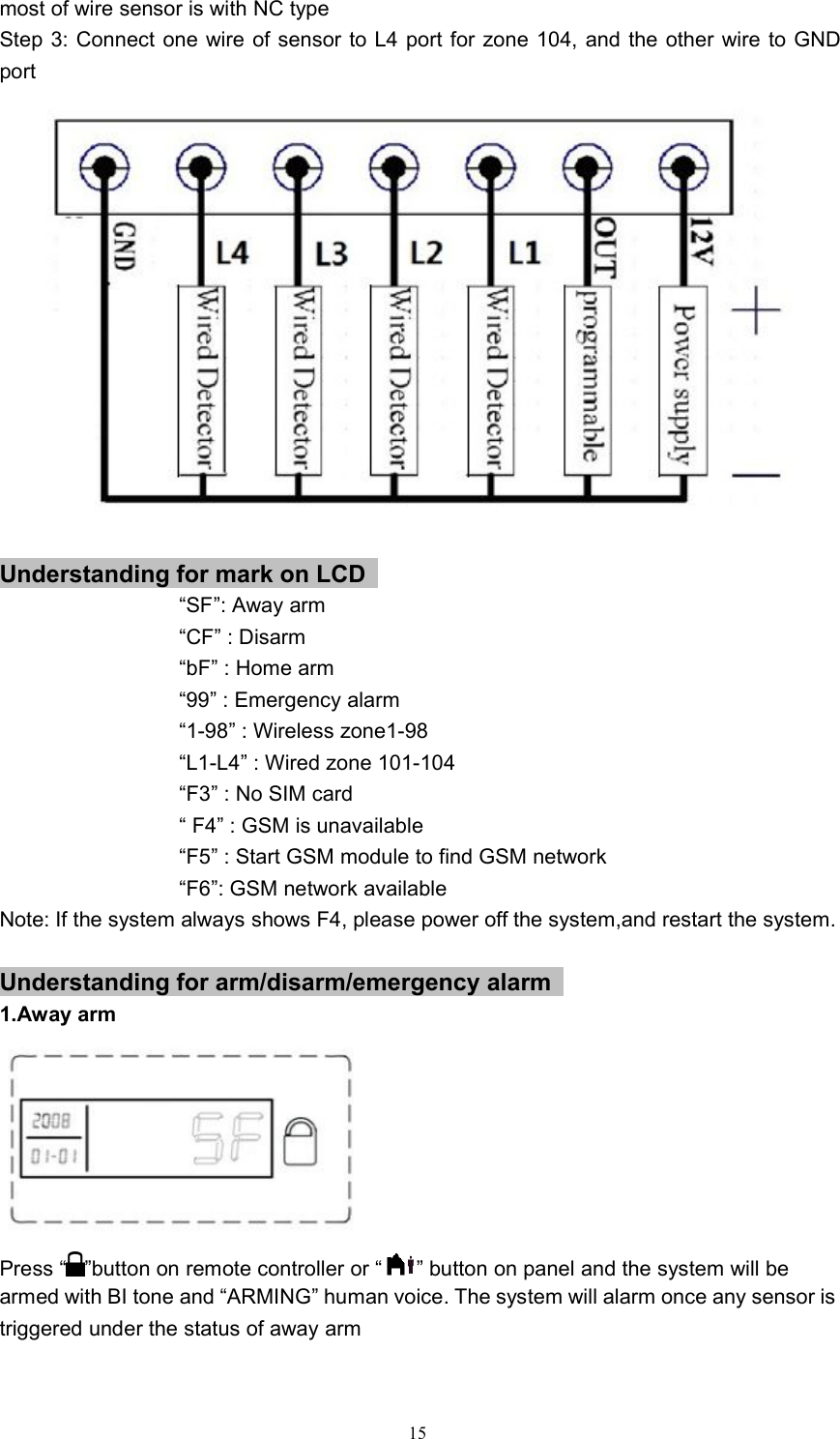
![141:Enable,upload alarm information, except for arm/disarminformation0: Disable2.System ID for CID setting via SMSUser can set unique ID for each system to work with CID protocol CMS.This operation needs to set via SMSSMS Command :【password】+【*】+【0】+【9】+【A】+【ID】+【*】A= 4 digitsExample, if user wants to set 6868 as system ID for CID CMS, send SMS0000*096868ID* to the system3.Alarm code for CID protocol network station settingCID defined that different alarm has its unique alarm code, so that CMSwill recognize the alarm type according to the codeCommand: [*]→[0]→[9→[A]→[B]→[*]A=zone number (3 digits required)B=CID alarm code (3 digits required)For example,[*]→[0]→[9→[002]→[110]→[*] , 002 means zone 2, 110 is the alarm code offire alarm, which is defined by CID protocolUnderstanding for wire sensor connection1.Enable/disable wire zone settingUser can disable or enable 4 pcs of wire zones as per the followingcommand. Default setting is disableEnable Command: [*]→[0]→[6]→[1]→[*]Disable command: [*]→[0]→[6]→[0]→[*]2.Wire zone No/NC type settingUser can set the wire zones with normal open type or normal close typeas per the following command. (Default setting is normal open type)Command: [*]→[9]→[A]→[B]→[*]A=zone number from 101-104. 101 for L1, 102 for L2, 103 for L3, 104for L4.B=0/1/. 0: normal close. 1:normal openExample: Require to set wire zone 103 to be normal close for wire door sensor, user canpress the command on the panel [*]→[9]→[103]→[0]→[*]3.Wire sensor installation:Take wire zone 104 with wire door sensor for exampleStep 1: User need to enable the wire zone by command:[*]→[0]→[6]→[1]→[*]. The defaultsetting is disable wire zonesStep 2: Program wire zone 104 with NC type by command [*]→[9]→[104]→[0]→[*]. Note:](https://usermanual.wiki/RF-Engineering-and-Energy-Resource/KI-GSM904/User-Guide-3050493-Page-15.png)