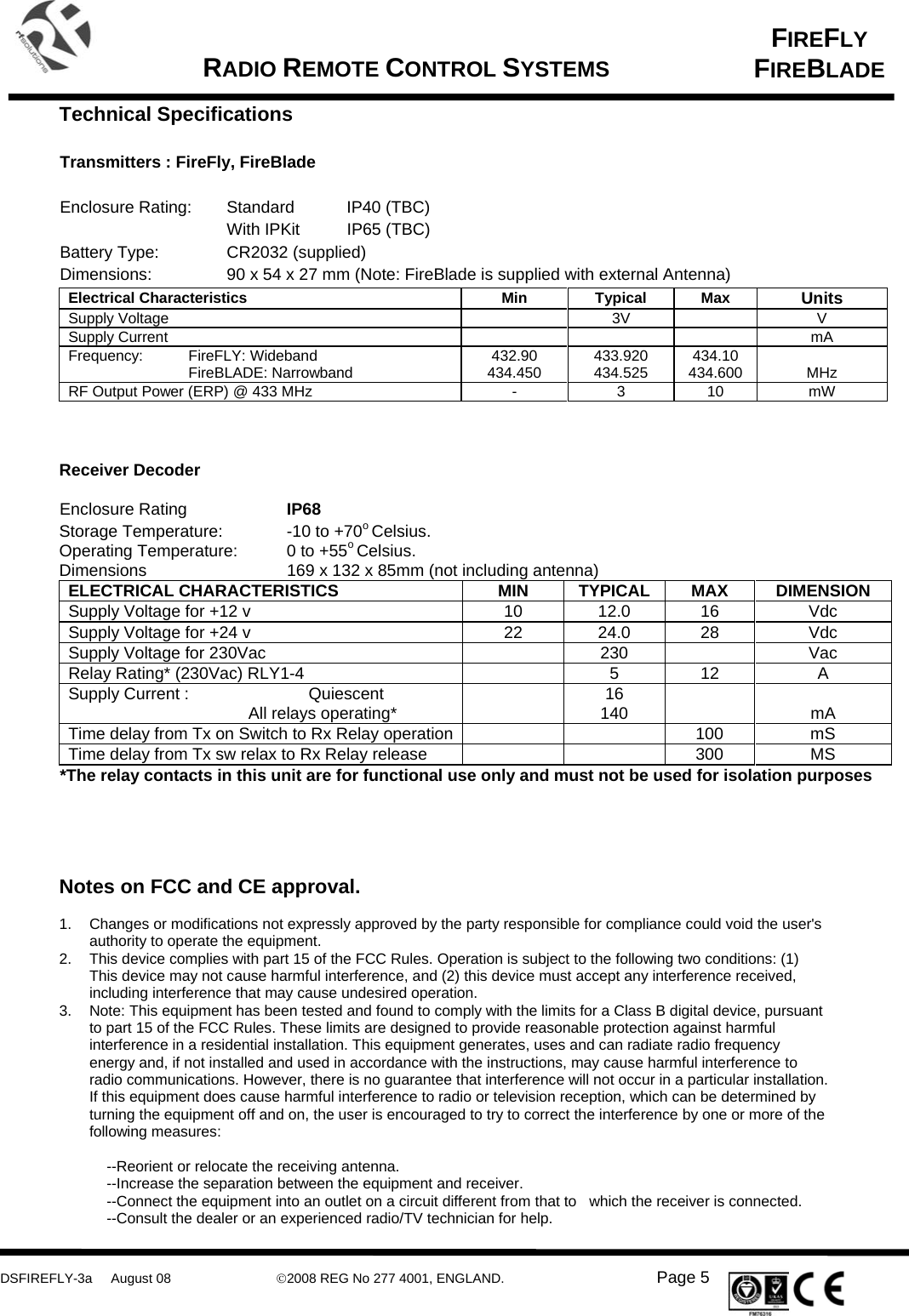
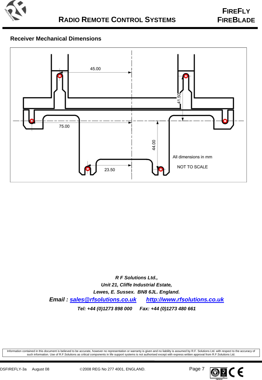
RF Solutions FIRE001 Handheld 8-button Remote Control Transmitter User Manual DS FIREFLY 3a

RF Solutions Ltd. Handheld 8-button Remote Control Transmitter DS FIREFLY 3a

User Manual

     DSFIREFLY-3a     August 08  ©2008 REG No 277 4001, ENGLAND.   Page 1   FIREFLY FIREBLADE   RADIO REMOTE CONTROL SYSTEMS    Applications • Lighting Control • General Purpose Remote Switching • Industrial remote Switching • Access Control  Description A Range of general purpose remote control systems    Installation simply requires connections to power supply and the output relay screw terminals. The output relays are activated by the button press on the transmitter encoder.   Housed in a rugged IP68 weatherproof enclosure, the receiver has the capacity to learn up to 15 transmitter button pairings. These are memorised even if the power is removed. Each individual switch on each of the transmitters may be paired with any or all of the receiver relay outputs. The decoder is supplied in an IP68 rated enclosure with Cable Gland and wall mounting lugs.      Features • 1,2,4 or 8 Channel Systems • 12 / 24Vdc or 230Vac Supply • CE and FCC Approved Tx1 • Range  FireFly up to 100 metres  FireBlade up to 500 metres • Reliable FM Technology • High Security RF Protocol • ‘Easy Learn’ Tx Encoder Feature • Easy Installation Via Screw Terminals. • 4 Relays 6A @ 230Vac • Momentary / Latch / Timed Outputs • Timed Output Adjustable 0 To 5 mins • Receiver Rated IP68 • Versatile operation modes: Many to Many, One to Many, Many to One.                                                                                                             1 See FCC conditions Page 6
     DSFIREFLY-3a     August 08  ©2008 REG No 277 4001, ENGLAND.   Page 2   FIREFLY FIREBLADE   RADIO REMOTE CONTROL SYSTEMS    FireFly Systems LOS Range 100m       Part Number  Description  Freq (MHz)  Range** (Metres) FIREFLY-S1  FM RC System 1 ch  433.92 100 FIREFLY-S2  FM RC System 2 ch  433.92 100 FIREFLY-S4  FM RC System 4 ch  433.92 100   Additional FireFly Transmitters         Part Number  Description  Freq (MHz)  Range** (Metres) FIREFLY-TX1  Transmitter 1 switch  433.92 100 FIREFLY-TX2  Transmitter 2 switch  433.92 100 FIREFLY-TX4  Transmitter 4 switch  433.92 100 FIREFLY-TX8  Transmitter 8 switch  433.92 100 FIREFLY-TX-IPKIT  Belt Clip and ’O’ Ring, Seals Transmitter to IP67   FireBlade Systems LOS Range 500m       Part Number  Description  Freq (MHz)  Range** (Metres) FIREBLADE-S1  FM RC System 1 ch  434.525 500 FIREBLADE-S2  FM RC System 2 ch  434.525 500 FIREBLADE-S4  FM RC System 4 ch  434.525 500   Additional FireBlade Transmitters       Part Number  Description  Freq (MHz)  Range** (Metres) FIREBLADE-TX1  Transmitter 1 switch  434.525 500 FIREBLADE-TX2  Transmitter 2 switch  434.525 500 FIREBLADE-TX4  Transmitter 4 switch  434.525 500 FIREBLADE-TX8  Transmitter 8 switch  434.525 500 FIREFLY-TX-IPKIT  Belt Clip and ’O’ Ring, Seals Transmitter to IP67   ** Range stated is optimum, direct line of sight. In worst conditions this can be reduced significantly.   Custom Options These systems may be supplied as OEM units. Both transmitter and receiver use overlay stickers as part of the assembly which may easily be customised to incorporate any other logo etc. Please contact our sales dept for further information.
     DSFIREFLY-3a     August 08  ©2008 REG No 277 4001, ENGLAND.   Page 3   FIREFLY FIREBLADE   RADIO REMOTE CONTROL SYSTEMS     Power Supply This unit is designed to be a fixed installation, operated from either 12/24Vdc or 230Vac.  Under no circumstances should the receiver be connected to more than one supply.  Before removing the cover ensure that the mains input supply is isolated.  Maintenance to the product that involves removal of the cover should only be carried out by a competent person or qualified electrician.  Data Outputs Each output relay provides an isolated switch. Connections are Common (COM), Normally Open (NO) and Normally Closed (NC).           Connecting a Relay output to an Application Below is a simple example showing one possible way to wire a relay in order to give switched power to an external load:      When the relay is energised the ‘COM’ connects to ’NO’ and power is applied to the Load.            Pairing a Transmitter to a Receiver Each transmitter has a unique identity. Each time a switch is pressed, the transmitter emits a highly secure RF signal (appears as a random encrypted data stream). The Receiver can learn this encrypted signal and allocate to an output. Any transmitter switch may be paired to one or many of the receiver’s outputs, or a transmitter single switch may be paired to any number of receiver’s outputs to enable a powerful and flexible remote control system.  The only limitation is that each receiver has a maximum capacity of 15 pairings, these can be from the same or any number of transmitters. Hint: the same transmitter may be taught to any number of receivers to create ‘master keys’.  COMNONCRelay Connections whenTransmitter NOT OperatingCOMNONCRelay Connections when Transmitter OPERATINGCOMN.O .N.C.105 RECEIVER UNITRELAY OUTPUT1+12V0V+12V0VSUPPLYLOAD0V +12V
     DSFIREFLY-3a     August 08  ©2008 REG No 277 4001, ENGLAND.   Page 4   FIREFLY FIREBLADE   RADIO REMOTE CONTROL SYSTEMS      To learn a new transmitter switch follow this procedure Any transmitter button can be learnt to one or many of the receiver output relays.  Each button must be learnt to each relay individually by following this procedure:  1.  To select the receiver output relay to learn to: a.  Briefly press the receiver Learn switch (SW1) once b.  The Learn LED will flash once to indicate output relay 1 is selected c.  After the LED stops flashing, press the Learn switch again to select the next relay channel  d.  Repeat step c until the required output relay is selected. 2.  Press the button on the transmitter you want to learn to the relay output. 3.  The Learn LED will then illuminate, press the same transmitter button again. 4.  The Learn LED will then flash to indicate learning is complete.  5.  To test the operation, press the transmitter button again and you will hear the relay ‘click’ as it operates.     Erasing Receivers Memory  1.  Press and hold the receiver Learn Switch for approx 10 seconds.  2.  When the Learn LED turns OFF all memory is erased 3.  This is factory default state which is indicated by all output LED’s flashing together. NOTE: You cannot erase individual Tx encoders   Receiver Outputs      The jumper links configure the outputs to be Momentary, Latching or Timed. The jumper links are made / removed by a small link ‘cap’ placed over the pin header.   Jumper Links (LK2 - 4)  Outputs 2 - 4 Open  Mom (The Output operates for as long as the transmitter switch is held on) Connected  Latch  (The Output changes state each time the Transmitter is operated)  LK0 LK1  Relay Outputs Open Open  Output 1 Momentary Open Connected  Output 1 Latching Connected Open  All Outputs fixed to ½ Second Momentary o/p Connected Connected Output 1, 0 to 5 minutes using Timer selection Potentiometer.
     DSFIREFLY-3a     August 08  ©2008 REG No 277 4001, ENGLAND.   Page 5   FIREFLY FIREBLADE   RADIO REMOTE CONTROL SYSTEMS    Technical Specifications  Transmitters : FireFly, FireBlade  Enclosure Rating:  Standard  IP40 (TBC) With IPKit  IP65 (TBC) Battery Type:    CR2032 (supplied) Dimensions:    90 x 54 x 27 mm (Note: FireBlade is supplied with external Antenna) Electrical Characteristics  Min  Typical  Max  Units Supply Voltage    3V    V Supply Current        mA Frequency: FireFLY: Wideband   FireBLADE: Narrowband  432.90 434.450  433.920 434.525  434.10 434.600   MHz RF Output Power (ERP) @ 433 MHz  -  3  10  mW    Receiver Decoder   Enclosure Rating    IP68  Storage Temperature:   -10 to +70o Celsius.  Operating Temperature:   0 to +55o Celsius. Dimensions      169 x 132 x 85mm (not including antenna) ELECTRICAL CHARACTERISTICS  MIN  TYPICAL  MAX  DIMENSION Supply Voltage for +12 v  10  12.0  16  Vdc Supply Voltage for +24 v  22  24.0  28  Vdc Supply Voltage for 230Vac    230    Vac Relay Rating* (230Vac) RLY1-4    5  12  A Supply Current :  Quiescent     All relays operating*   16 140    mA Time delay from Tx on Switch to Rx Relay operation     100  mS Time delay from Tx sw relax to Rx Relay release      300  MS *The relay contacts in this unit are for functional use only and must not be used for isolation purposes     Notes on FCC and CE approval.  1.  Changes or modifications not expressly approved by the party responsible for compliance could void the user's authority to operate the equipment. 2.  This device complies with part 15 of the FCC Rules. Operation is subject to the following two conditions: (1) This device may not cause harmful interference, and (2) this device must accept any interference received, including interference that may cause undesired operation. 3.  Note: This equipment has been tested and found to comply with the limits for a Class B digital device, pursuant to part 15 of the FCC Rules. These limits are designed to provide reasonable protection against harmful interference in a residential installation. This equipment generates, uses and can radiate radio frequency energy and, if not installed and used in accordance with the instructions, may cause harmful interference to radio communications. However, there is no guarantee that interference will not occur in a particular installation. If this equipment does cause harmful interference to radio or television reception, which can be determined by turning the equipment off and on, the user is encouraged to try to correct the interference by one or more of the following measures:  --Reorient or relocate the receiving antenna. --Increase the separation between the equipment and receiver. --Connect the equipment into an outlet on a circuit different from that to   which the receiver is connected. --Consult the dealer or an experienced radio/TV technician for help.
     DSFIREFLY-3a     August 08  ©2008 REG No 277 4001, ENGLAND.   Page 6   FIREFLY FIREBLADE   RADIO REMOTE CONTROL SYSTEMS
     DSFIREFLY-3a     August 08  ©2008 REG No 277 4001, ENGLAND.   Page 7   FIREFLY FIREBLADE   RADIO REMOTE CONTROL SYSTEMS     Receiver Mechanical Dimensions                     R F Solutions Ltd., Unit 21, Cliffe Industrial Estate, Lewes, E. Sussex.  BN8 6JL. England. Email : sales@rfsolutions.co.uk http://www.rfsolutions.co.uk Tel: +44 (0)1273 898 000  Fax: +44 (0)1273 480 661   Information contained in this document is believed to be accurate, however no representation or warranty is given and no liability is assumed by R.F. Solutions Ltd. with respect to the accuracy of such information. Use of R.F.Solutions as critical components in life support systems is not authorised except with express written approval from R.F.Solutions Ltd.

Navigation menu