Radio Thermostat of America 6021R Wall Unit (2.4GHz Transceiver) User Manual 711 002 IBIE 6021z Install guide 1nov07 ai
Radio Thermostat Company of America, Inc Wall Unit (2.4GHz Transceiver) 711 002 IBIE 6021z Install guide 1nov07 ai
UserManual.wiki
>
Radio Thermostat of America
>
6021R User Manual
User Manual
Navigation menu
Upload a User Manual
Namespaces
Wiki Guide
HTML
PDF
Info
Views
User Manual
Discussion / Help
Navigation
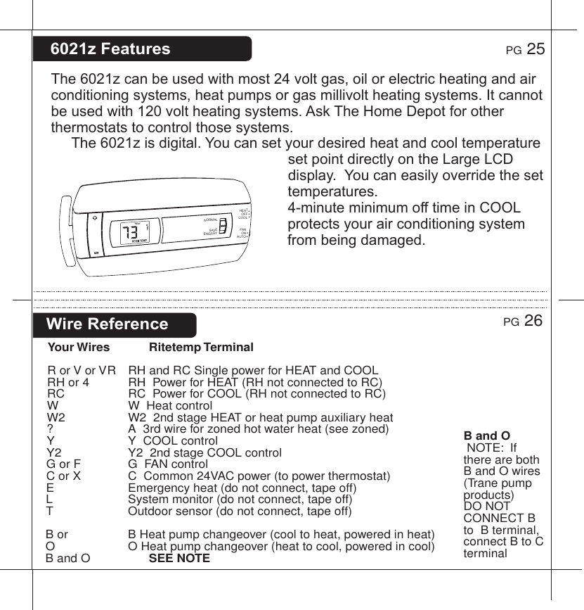
![Wire Reference contYour Wires Ritetemp TerminalLennox Heat Pump V or VR or R RH M or Y YY or W or W2 W2F or G GR or O OX or X2 or C C Trane Products [American Standard]BCW or W1 W2Zoned SystemsYour Wires Ritetemp Terminal2 wire Zoned Hot Water R RHW W3 Wire Zoned Hot Water Motor Driven ValvesR RHW WY (the 3rd wire) A3 Wire Zoned Hot Water Solenoid ValvesR RHW AY (the 3rd wire) WHEAT PUMPPUMP AUX ELECTCENTIGRADEOPENAUX ONLYOPENPUMP AUXGAS OR OILOPENFAHRENHEITCLOSEDCLOSED orCLOSEDCLOSEDNORMAL HEAT (NO PUMP)OPENNORM/PUMP/AUXCENTIGRADERESET UNITAFTER JUMPER CHANGESELECTTYPEAUXFAHRENHEITGAS/OILOPENELECTRICHEATCLOSEDFANCONTROLHEAT PUMP'SBOTH OPENPG 27PG 28Jumper ReferenceConfiguration jumpers allow your 6021z Thermostat to be adapted to many different HVAC control applications.654322RESETBINDING 3456](https://usermanual.wiki/Radio-Thermostat-of-America/6021R/User-Guide-881017-Page-15.png)