Radio Thermostat of America CT101R1 Low Power Communication Device Transmitter:908.4MHz transmitter User Manual CT101
Radio Thermostat Company of America, Inc Low Power Communication Device Transmitter:908.4MHz transmitter CT101
UserManual.wiki
>
Radio Thermostat of America
>
CT101R1 User Manual
CT101_User Manual
Navigation menu
Upload a User Manual
Namespaces
Wiki Guide
HTML
PDF
Info
Views
User Manual
Discussion / Help
Navigation
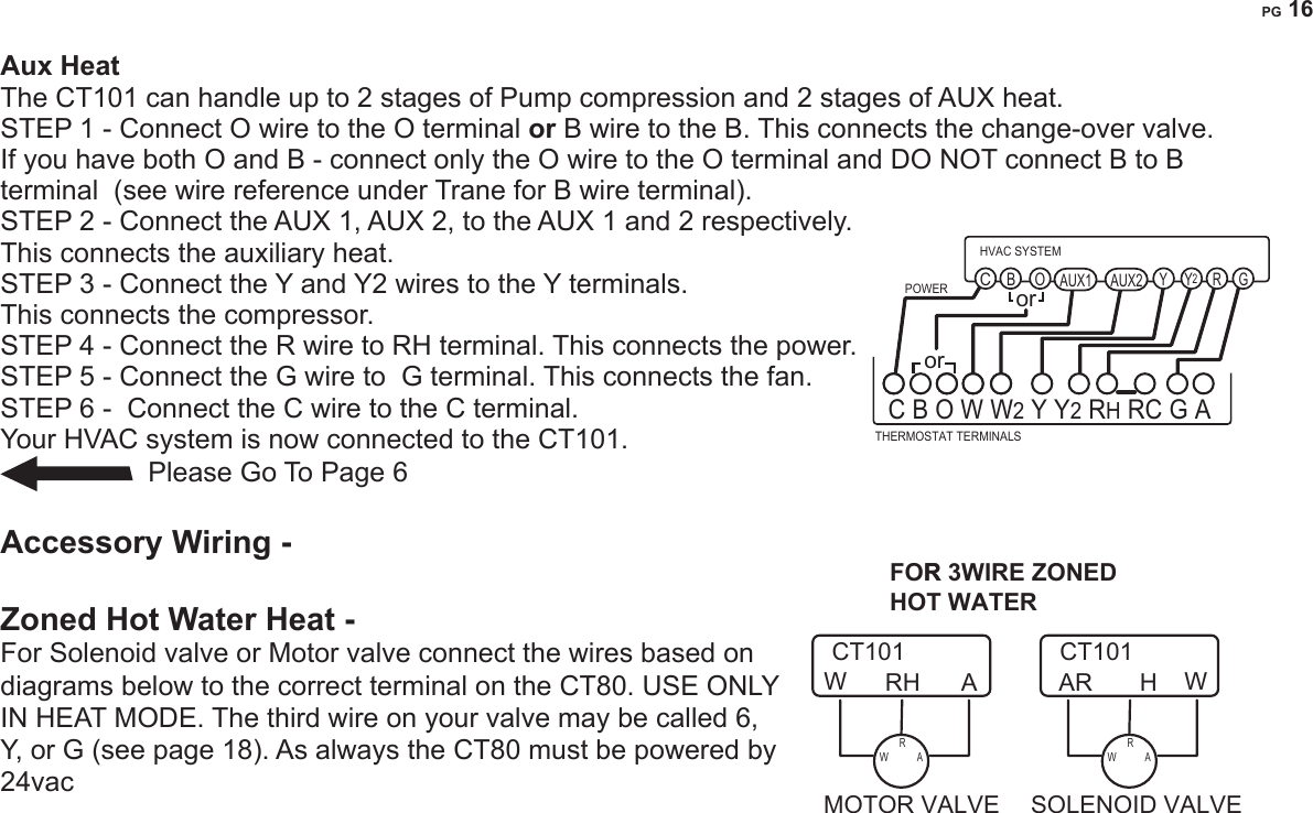
![PG 4What wires do you have? Make sure your wires are labeled. This may require you to nd the ‘other end’ connection for each wire on your heating or air conditioning equipment and read the label there. Refer to the Wire Reference page at end of install section for better understanding of wire labels from different HVAC system makers. IMPORTANT: The CT101 runs on 4 AA alkaline batteries and/or the C wire if available. If you do not have a C wire you can run a new wire from the HVAC or use a standard 12-24V [AC or DC] wall transformer. A constant power source is required when using a radio module. IMPORTANT: If you have both RH and RC you need to remove the jumper wire between these 2 terminals.Prepare Wires Please follow these guidelines for safe and secure wire connections:• You will need at least 2.6” of wire for each of your connections to the CT101. • If you do not have enough wire, splice additional wire to allow enough slack. • Terminals accept wires from 16-22awg.• Fan out wires below the hole as shown.• Remove insulation 1/8” from the tip of each wire.• When handling, take care not to damage the labels for each wire. GCYRHW2.6"from HVAC SystemJumper wireWire TerminalsY RH RC G A Y2](https://usermanual.wiki/Radio-Thermostat-of-America/CT101R1/User-Guide-1753236-Page-5.png)
![PG 4PG 5Find the step-by-step diagram for your system • Select the referenece page with your wiring diagram and set-up information below.• The C-wire is optional but prefered for all installations [shown dotted in diagrams]. • Hot Water systems accessoroes are on Page 16• If your combination of wires is not above you can use the wiring table at the end if the install section to determine your connections, contact customer support for help.GC W Y RH RC G 5 WireHeat/CoolFrom HVACRCCYRHWC W Y R G 4 Wire Heat/CoolFrom HVACGCYRWC W R G 3 Wire HeatFrom HVACCRGWFrom HVACCWC W R R2 Wire Heat WIRESWIRESWIRESWIRESGRC Wn Yn R G Multi-stage CoolMulti-Stage HeatFrom HVACYnCWnC B or O AUXn Yn R G Multi-stage Heat Pump w/ Multi-stage Aux HeatFrom HVACRCOorWnBGYnGC B or O Y R G 4 Wire Heat Pumpw/o Aux HeatFrom HVACRCOorYBWIRESWIRESWIRESGo To Page 15 Go To Page 16Go To Page 15Go To Page 13 Go To Page 14 Go To Page 14Go To Page 13](https://usermanual.wiki/Radio-Thermostat-of-America/CT101R1/User-Guide-1753236-Page-6.png)
![PG 8HVAC Selection • Set the HVAC TYPE switch in the NORM position if you have conventional natural gas, propane, oil, or electric heat. If you have a HEAT PUMP system set the HVAC TYPE switch to HP. They are located in the battery compatrment. • Set the HEAT TYPE switch in the GAS position if you have normal gas or oil heat or if you have a heat pump with gas or oil auxiliary heat. Put the HEAT SOURCE in the ELEC position if you have normal electric heat or if you have a heat pump with electric auxiliary heat. Install 4 AA Batteries • Install 4 AA alkaline batteries [required] following the marked polarity in the battery compartments. Put the battery in negative end rst against the spring, then push the positive end in. IMPORTANT: Press the RESET button (under top cover) to implement the HVAC switch selections. • With all the wires connected it is time to turn the AC power back on. Do this at the breaker you used to switch it off. The CT101 will power-up in the OFF mode. Your CT101 is not congured to operate your HVAC system yet. You must now congure your thermostat for your HVAC system.AAAA AAAAHEAT�PUMPHVACTYPEHVACTYPEHEAT�TYPEHEATTYPENORMAL GASELEC](https://usermanual.wiki/Radio-Thermostat-of-America/CT101R1/User-Guide-1753236-Page-9.png)
![PG 10HVAC Setup on Screen IMPORTANT: Make sure the CT101 is powered up and the mode is set to OFF. HVAC selection switches must be set rst [pg 8].• With mode in OFF press MENU and touch HVAC SET UP.• Use +/- icons to select HVAC SET UP number on screen.The LCD display will show your selection and indicate the number of stages you have selected. During setup, 2nd stage will blink when both heat and cool have 2nd stages. If you have a Normal HVAC system and you want fast temperature recovery... HEAT and COOL select 12 stage HEAT, 1 stage COOL select 2 1 stage HEAT, 2 stage COOL select 3 2 stage HEAT, 2 stage COOL select 4 Caution Do not change he HVAC setup or HVAC selection switches if the thermostat is included to Z-Wave network. The HVAC system must be changed, rst EXCLUDE the thermostat from the network, change the HVAC setup, and INCLUDE the thermostat to the network. If you have a HEAT PUMP HVAC system...HEAT PUMP with no AUX heat select A2stage HEAT PUMP with no AUX select b HEAT PUMP with AUX heat select C HEAT PUMP with 2stage AUX heat select d 2stg HEAT PUMP with AUX heat select E 2stg HEAT PUMP with 2stg AUX heat select F HEAT2NDSTGHVACSETUP COOL](https://usermanual.wiki/Radio-Thermostat-of-America/CT101R1/User-Guide-1753236-Page-11.png)

![PG 18Wire Reference cont. Possible Wires What They Control Lennox Heat Pump V or VR or R RH Power for HEAT M or Y Y COOL controlY or W or W2 W2 2nd stage HEATF or G G Fan controlR or O OX or X2 or C C Trane Products [American Standard]B C 24VAC power (to power thermostat) W or W1 W2 2nd stage HEAT X2 Emergency heat (do not connect, tape off)Zoned Hot Water 2 wireYour Wires Thermostat TerminalR RHW W3 Wire Motor Driven ValvesR or 5 RH (power)W or 4 W (heat ON)Y or G or 6 (the 3rd wire) A (heat OFF)3 Wire Solenoid ValvesR RH (power)W A (heat ON)Y or G (the 3rd wire) W (heat OFF)](https://usermanual.wiki/Radio-Thermostat-of-America/CT101R1/User-Guide-1753236-Page-19.png)