Radio Thermostat of America CT102R1 Thermostat User Manual CT102 Manual REV 1
Radio Thermostat Company of America, Inc Thermostat CT102 Manual REV 1
UserManual.wiki
>
Radio Thermostat of America
>
CT102R1 User Manual
CT102 Manual REV 1
Navigation menu
Upload a User Manual
Namespaces
Wiki Guide
HTML
PDF
Info
Views
User Manual
Discussion / Help
Navigation

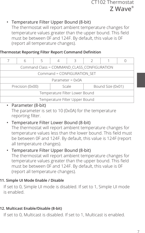
![WiringInstallation Guide CT1029Connecting Your WiresReference the Wire Diagram on page # to identify your wiring diagram and set-up information. If necessary, contact customer support for help.1. Connect a labeled wire only to a matching lettered terminal.2. Insert the wire in the terminal well and tighten the screw securely.The CT102 can be externally powered with a power source rated from 12V to 24V, AC or DC, at 300ma or greater. If used, connect to the C and RH terminals (no polarity).The 24VAC “C” wire is the other side of the 24VAC heating transformer and can be found where the other thermostat wires connect at the wall or at the furnace. Do not use the common or ground side of the line voltage.The CT102 runs on 4 AA alkaline batteries, the C wire (if available), or both batteries and the C-wire. If you do not have a C wire, you can run a new wire from the HVAC or use a standard 12-24V [AC or DC] wall transformer.The C-wire is optional but preferred for all installations.From HVAC SystemWW2CBOYY2 RH RC GACYWGRH](https://usermanual.wiki/Radio-Thermostat-of-America/CT102R1/User-Guide-2799671-Page-9.png)


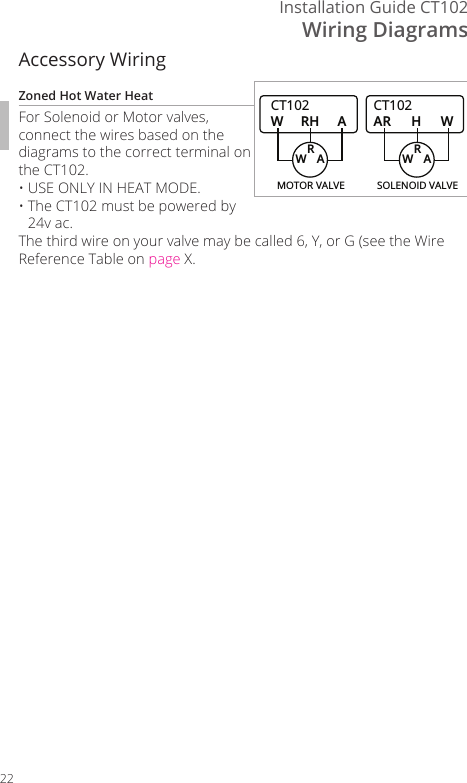
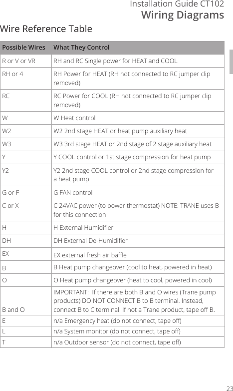
![Wiring DiagramsInstallation Guide CT10224Lennox Heat PumpV or VR or R RH Power for HEATM or Y Y COOL controlY or W or W2 W2 2nd stage HEATF or G G Fan controlR or O OX or X2 or C CTrane Products [American Standard]B C 24VAC power (to power thermostat)W or W1 W2 2nd stage HEATX2 Emergency heat. Do not connect, tape o.Zoned Hot Water 2 wireR RHW WMotor Driven Valves3 WireR or 5 RH (power)W or 4 W (heat ON)Y or G or 6 (the 3rd wire) A (heat OFF)Solenoid Valves3 WireR RH (power)W A (heat ON)Y or G (the 3rd wire) W (heat OFF)CT102 THERMOSTAT Z-WAVE® REFERENCE](https://usermanual.wiki/Radio-Thermostat-of-America/CT102R1/User-Guide-2799671-Page-24.png)