Radio Thermostat of America CT110R1 Thermostat User Manual CT110 Manual REV 1
Radio Thermostat Company of America, Inc Thermostat CT110 Manual REV 1
UserManual.wiki
>
Radio Thermostat of America
>
CT110R1 User Manual
CT110 Manual REV 1
Navigation menu
Upload a User Manual
Namespaces
Wiki Guide
HTML
PDF
Info
Views
User Manual
Discussion / Help
Navigation
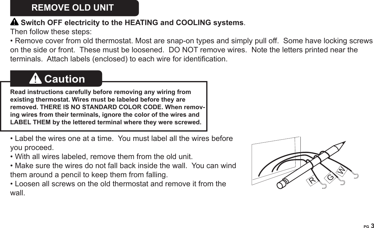
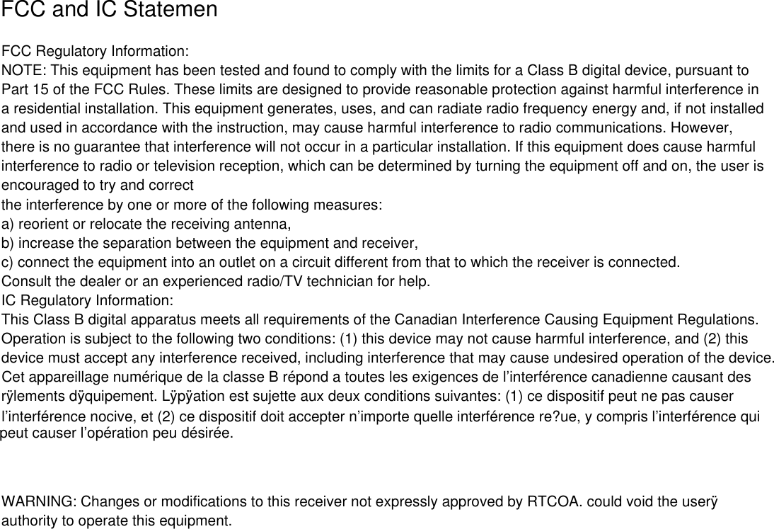
![PG 4What wires do you have? Make sure your wires are labeled. This may require you to nd the ‘other end’ connection for each wire on your heating or air conditioning equipment and read the label there. Refer to the Wire Reference page at end of install section for better understanding of wire labels from different HVAC system makers. IMPORTANT: The CT110 runs on 4 AA alkaline batteries and/or the C wire if available. If you do not have a C wire you can run a new wire from the HVAC or use a standard 12-24V [AC or DC] wall transformer. A constant power source is required when using a radio module. IMPORTANT: If you have both RH and RC you need to remove the jumper wire between these 2 terminals.Prepare Wires Please follow these guidelines for safe and secure wire connections:• You will need at least 2.6” of wire for each of your connections to the CT110. • If you do not have enough wire, splice additional wire to allow enough slack. • Terminals accept wires from 16-22awg.• Fan out wires below the hole as shown.• Remove insulation 1/8” from the tip of each wire.• When handling, take care not to damage the labels for each wire.Caution Do not allow wires to touch each other or parts on thermostat. Jumper wireY RH RC G A Y2Wire Terminals](https://usermanual.wiki/Radio-Thermostat-of-America/CT110R1/User-Guide-2642819-Page-4.png)

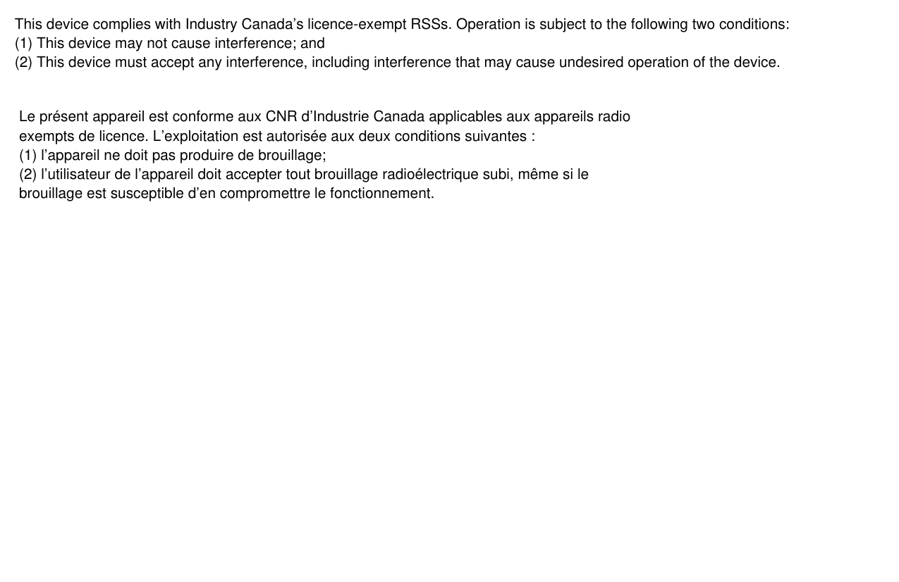
![PG 8Install 4 AA Batteries • Install 4 AA alkaline batteries [required] following the marked polarity in the battery compartments. Put the battery in negative end rst against the spring, then push the positive end in. The CT110 will power-up in the OFF mode. Your CT110 is not congured to operate your HVAC system yet. You must now congure your thermostat for your HVAC system before you mount it to the wall plate.Caution Special Thermostat Battery Cautions Always replace the batteries as soon as the low battery indicator displays. The thermostat is a battery powered device. You must be responsible to replace batteries before they run out. Failure to replace batteries can result in overheating or excessive cooling of your house.• Even if the low battery indicator display does not display, you should always replace the batteries at least once a year. Replacing the batteries also helps to prevent leakage that can corrode and damage the thermostat.• If you are leaving your home for a month or more, you should replace the batteries as a precaution against battery failure in your absence.+ 1.5v AA -+ 1.5v AA -+ 1.5v AA -+ 1.5v AA -+ 1.5v AA -](https://usermanual.wiki/Radio-Thermostat-of-America/CT110R1/User-Guide-2642819-Page-8.png)
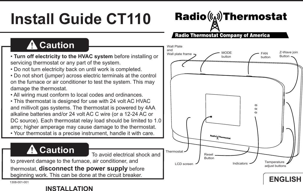
![PG 19Wire Reference cont. Possible Wires What They Control Lennox Heat Pump V or VR or R RH Power for HEAT M or Y Y COOL controlY or W or W2 W2 2nd stage HEAT or 2nd stage heat pump auxiliary heatF or G G Fan controlR or O OX or X2 or C C Trane Products [American Standard]B C 24VAC power (to power thermostat) W or W1 W 1st stage normal HEAT or 1st stage heat pump auxiliary heat X2 Emergency heat (do not connect, tape off)CZoned Hot Water Heat - For Solenoid valve or Motor valve connect the wires based on diagrams below to the correct terminal on the CT110. The third wire on your valve may be called 6, Y, or G. Your Wires...2 wire Thermostat TerminalR RHW W 3 Wire Solenoid ValvesR RH (power)W A (heat ON)Y or G (the 3rd wire) W (heat OFF) SOLENOID VALVEW A RH CT32 MOTOR VALVEW RH ACT32 FORR 3 WIRE HOT WATERWRAWRA](https://usermanual.wiki/Radio-Thermostat-of-America/CT110R1/User-Guide-2642819-Page-19.png)