RadioFrame Networks DH2 DH2 User Manual RFN Customer MOP 3 1
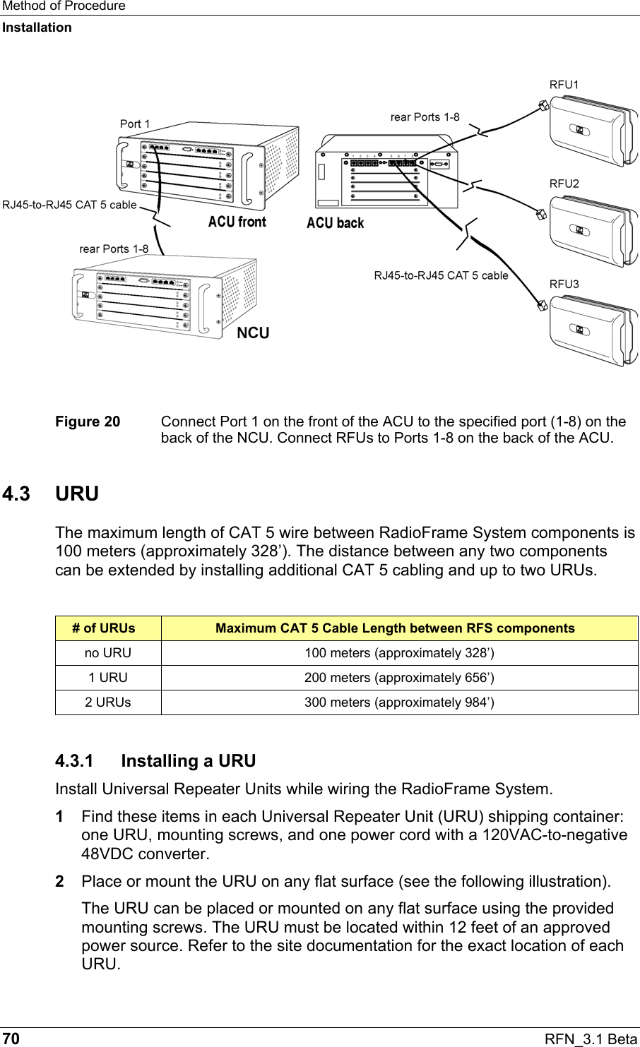
RadioFrame Networks, Inc DH2 RFN Customer MOP 3 1
UserManual.wiki
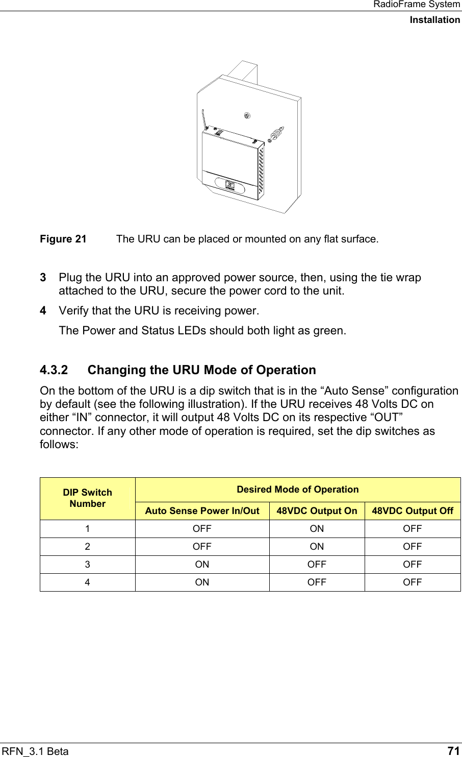
>
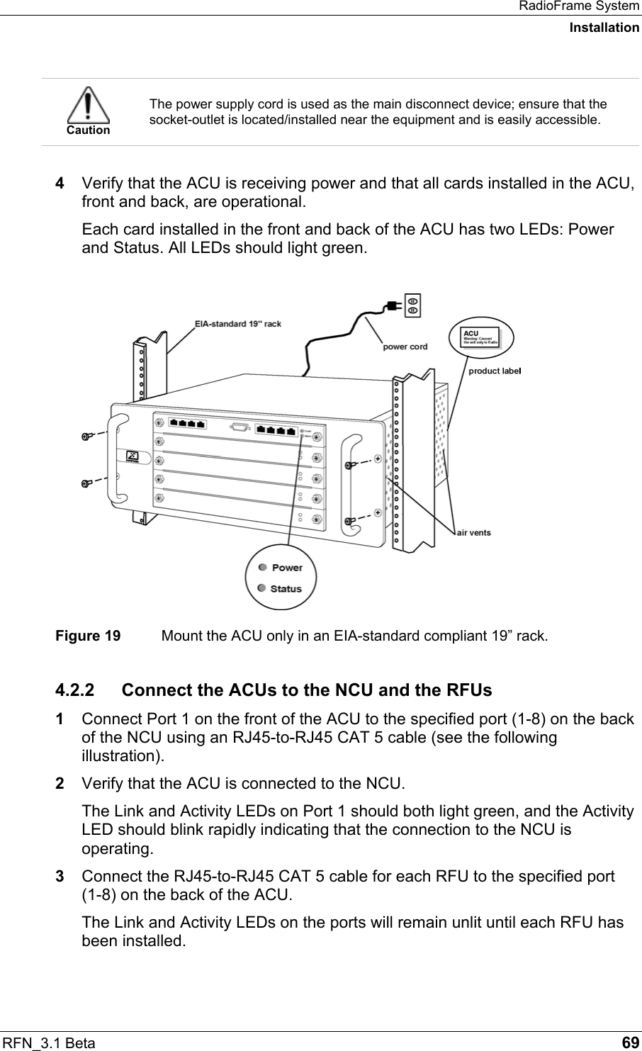
RadioFrame Networks
>
DH2 User Manual
Installation Guide
Navigation menu
Upload a User Manual
Namespaces
Wiki Guide
HTML
PDF
Info
Views
User Manual
Discussion / Help
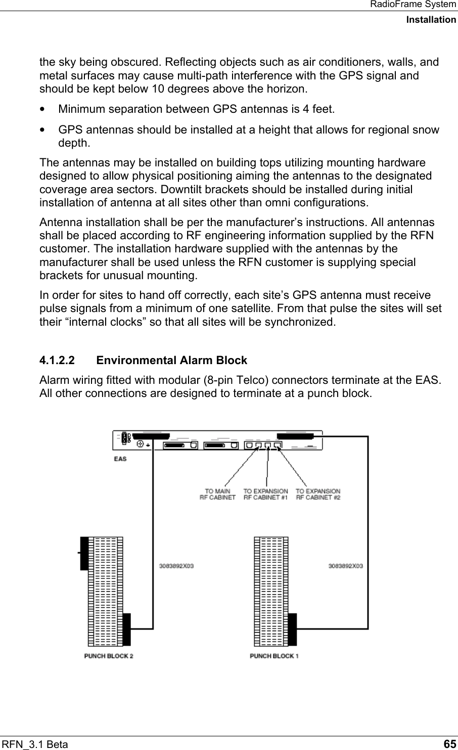
Navigation
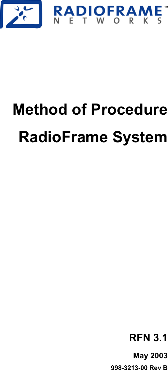

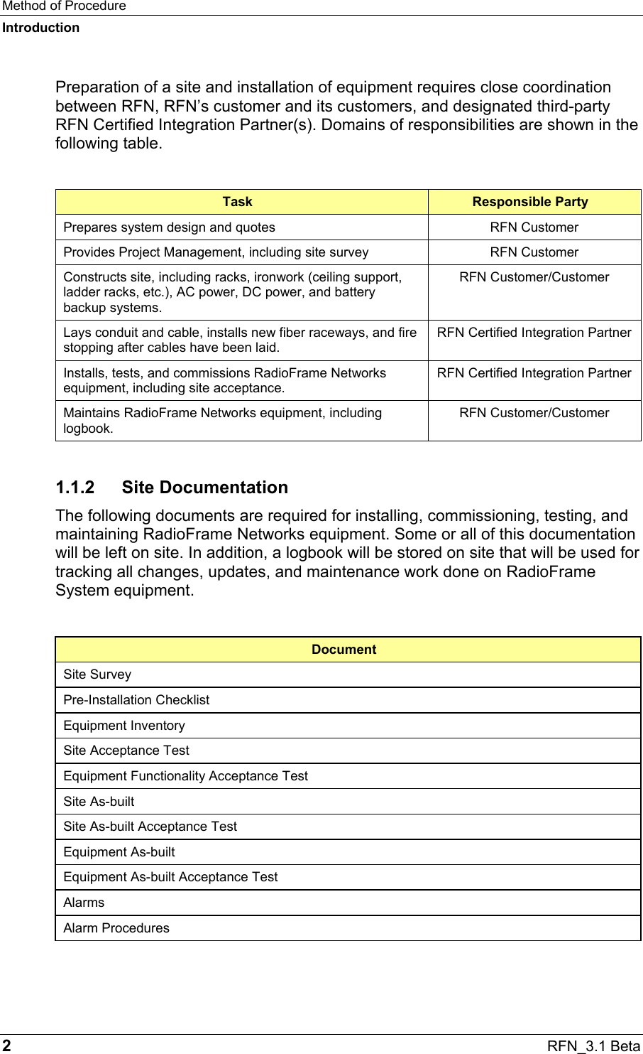
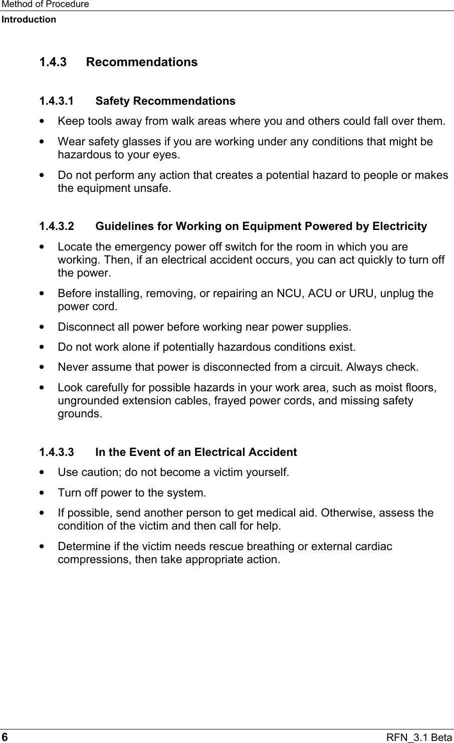
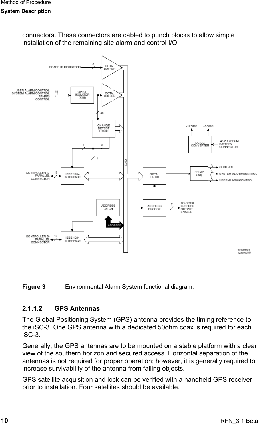
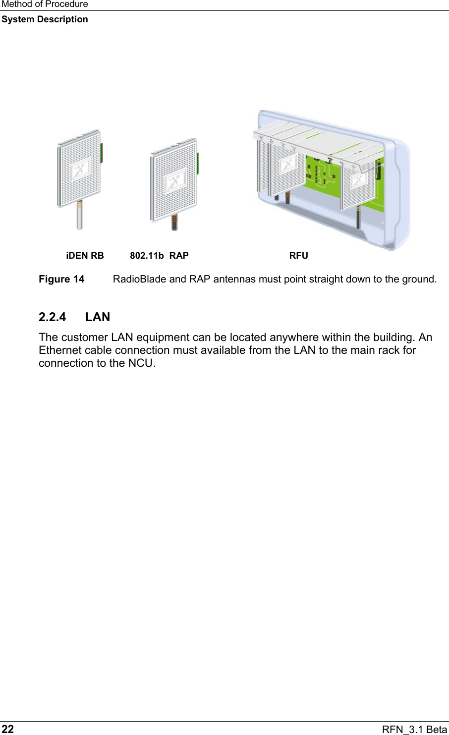
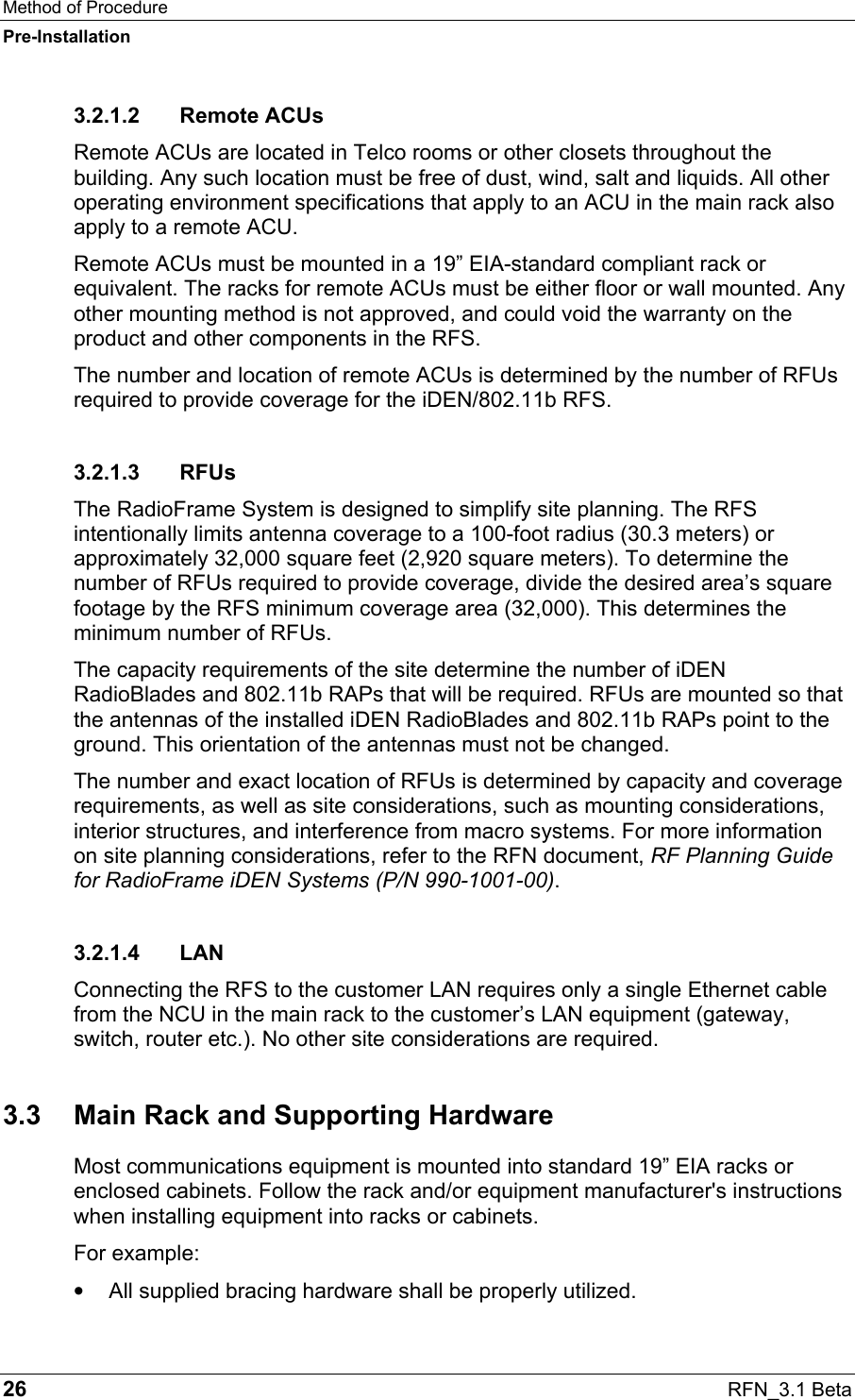
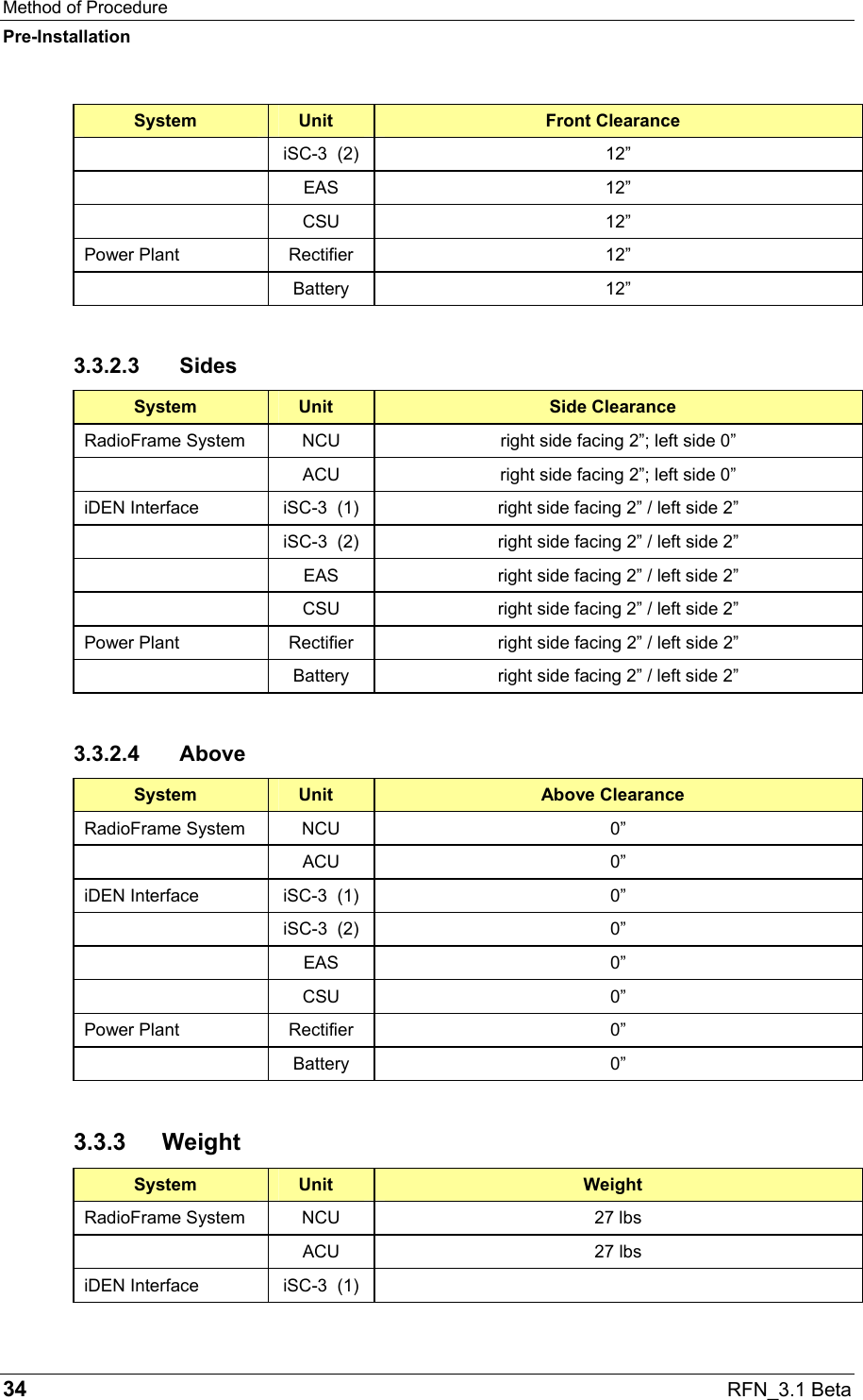
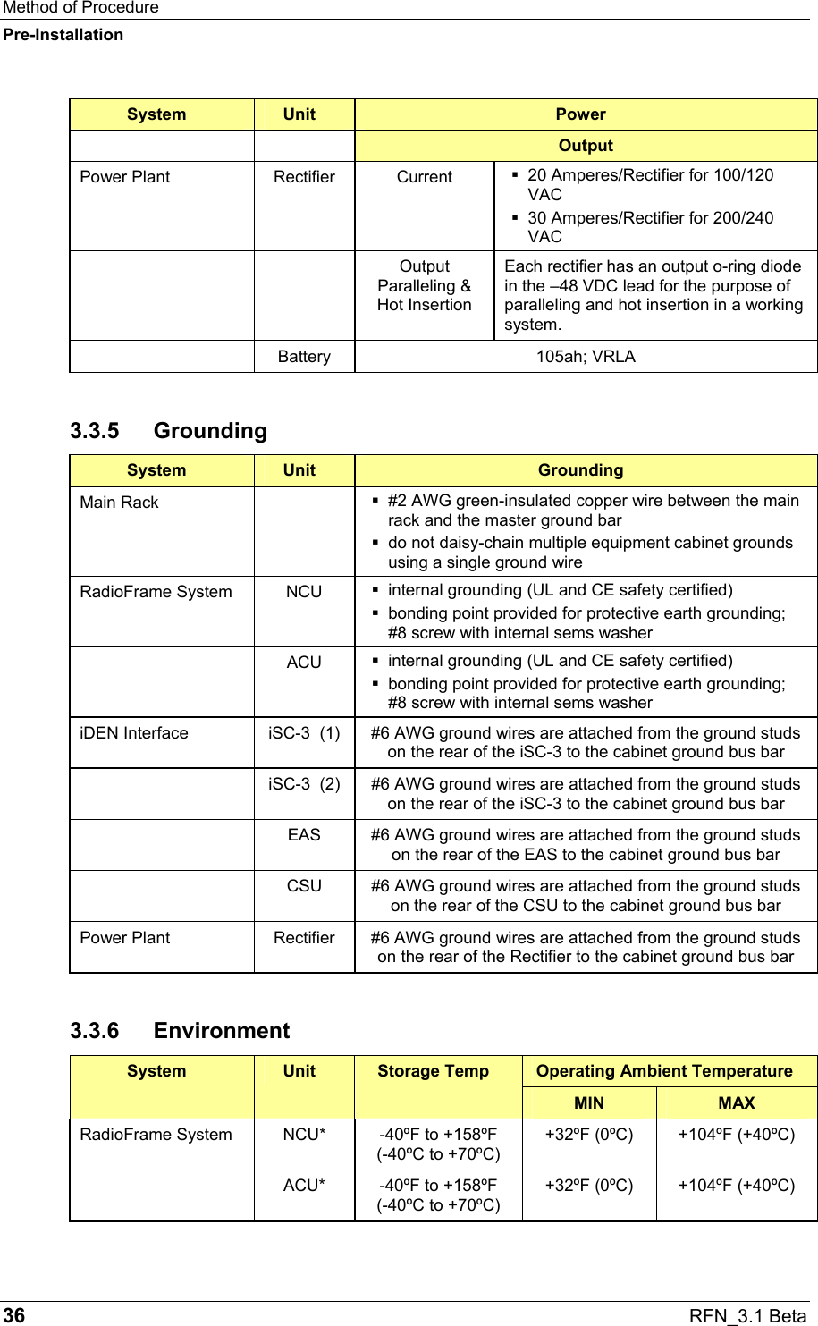
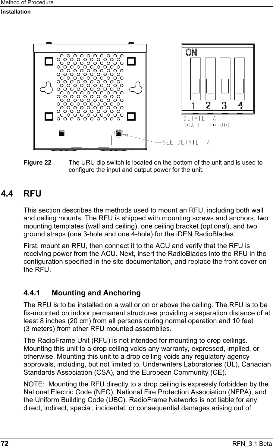
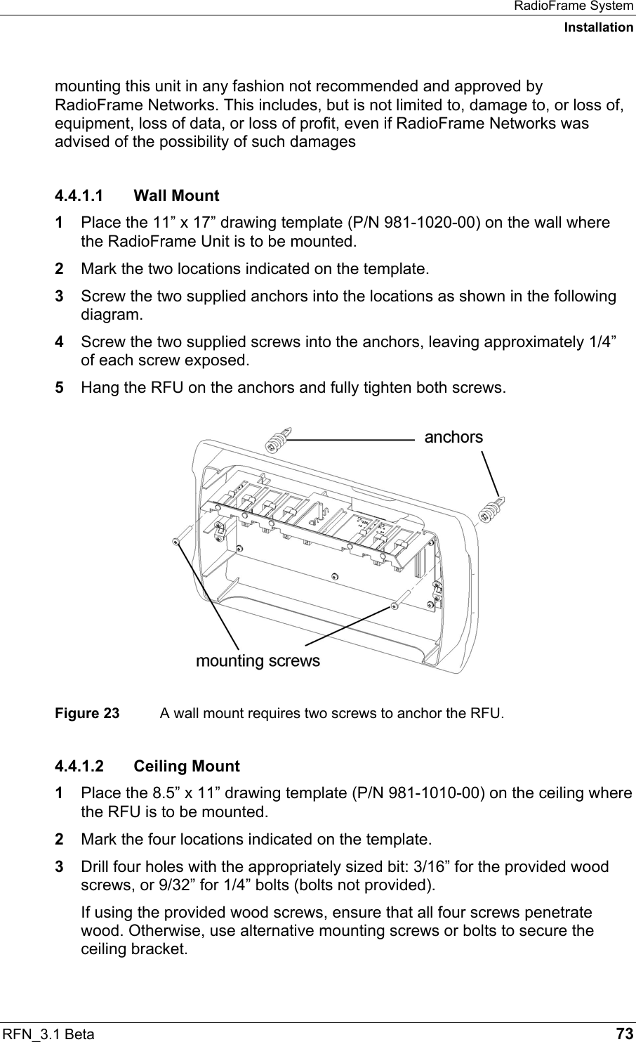
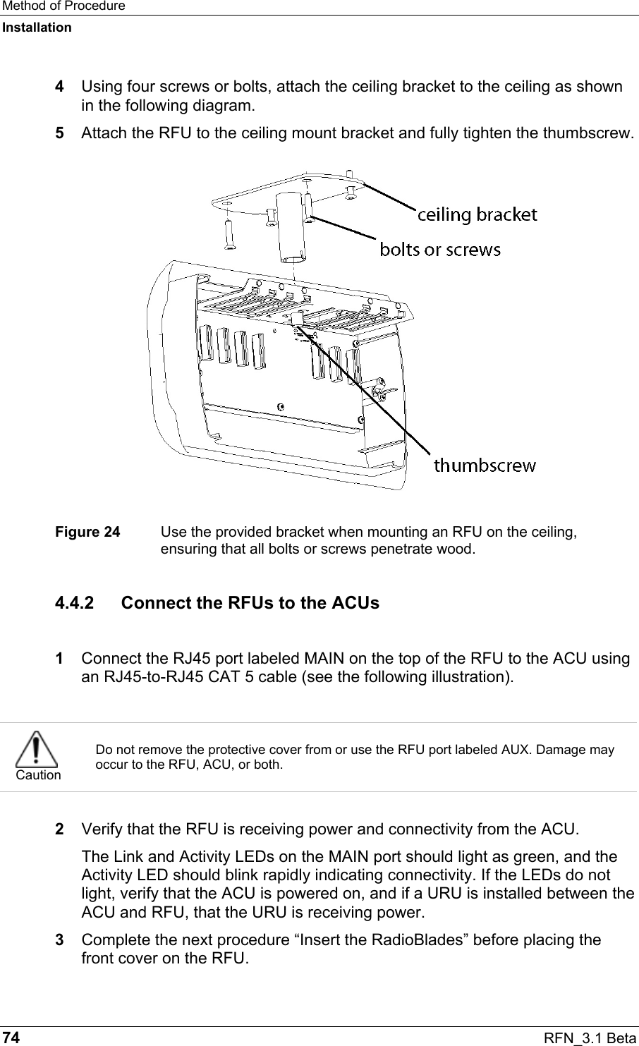
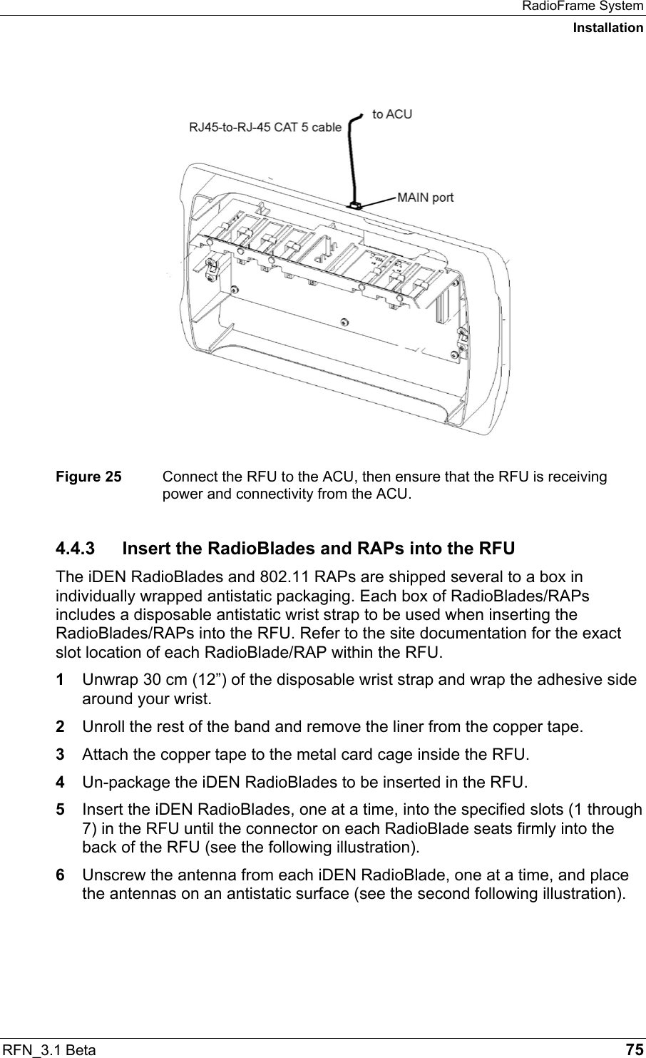
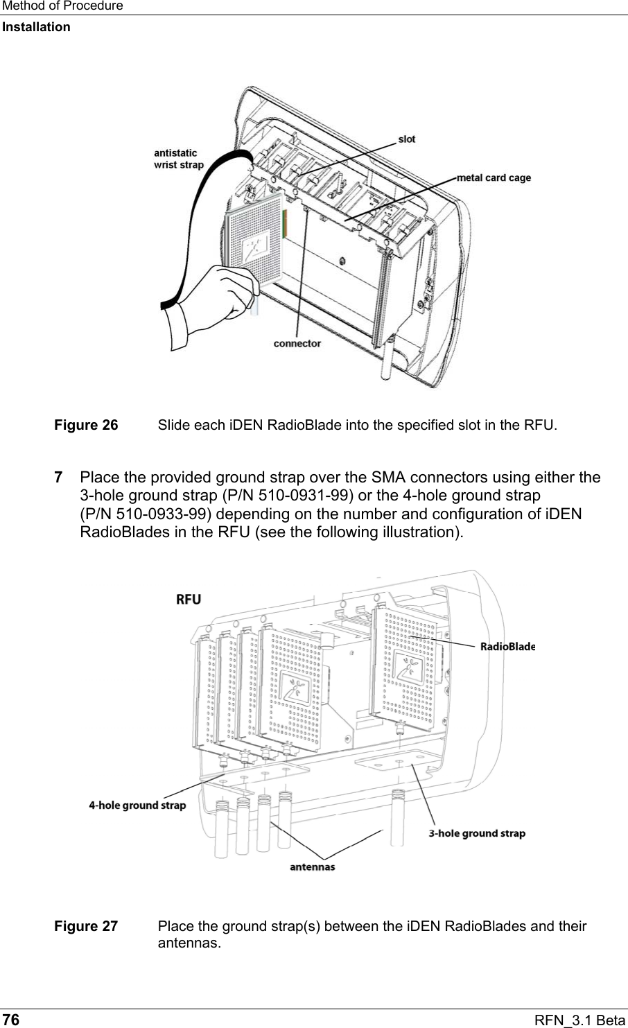
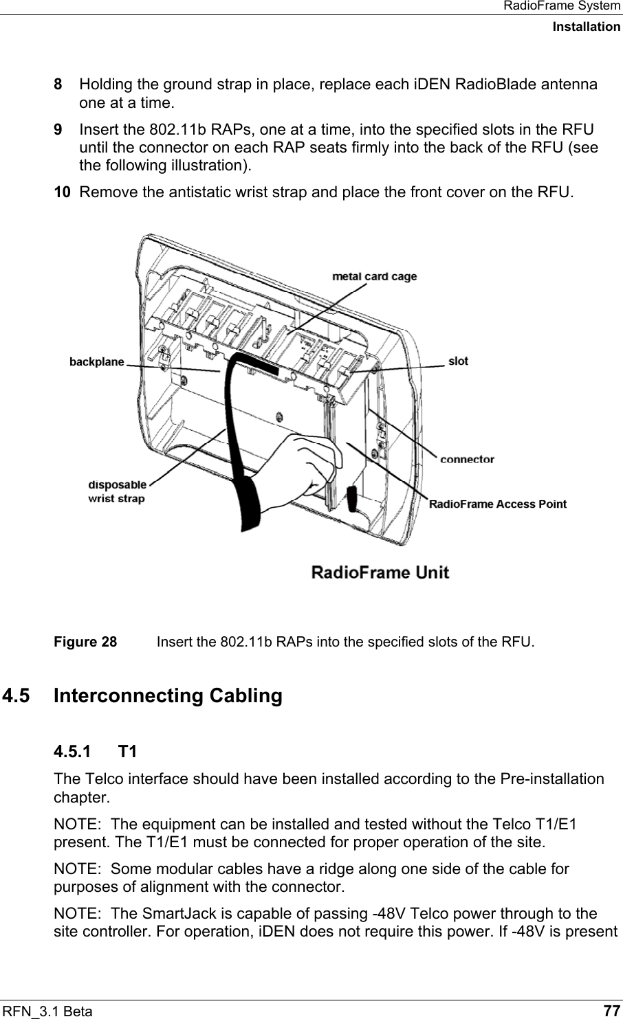
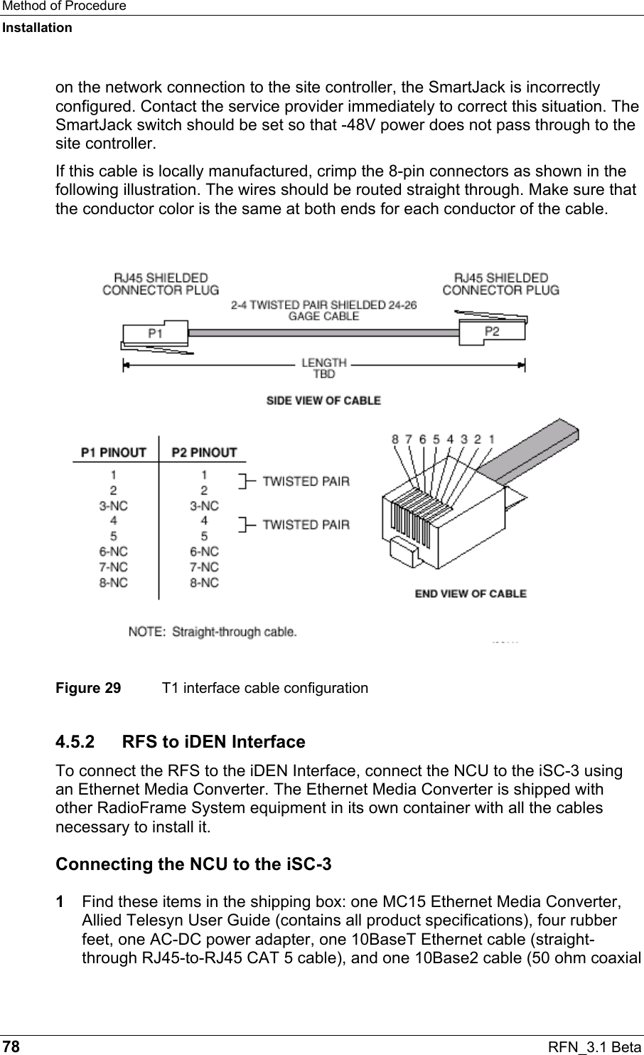
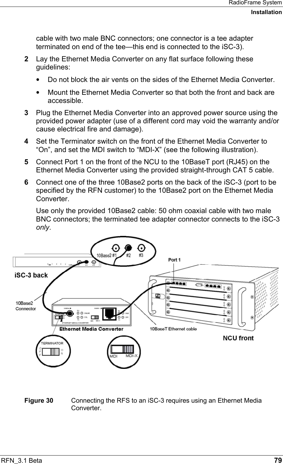
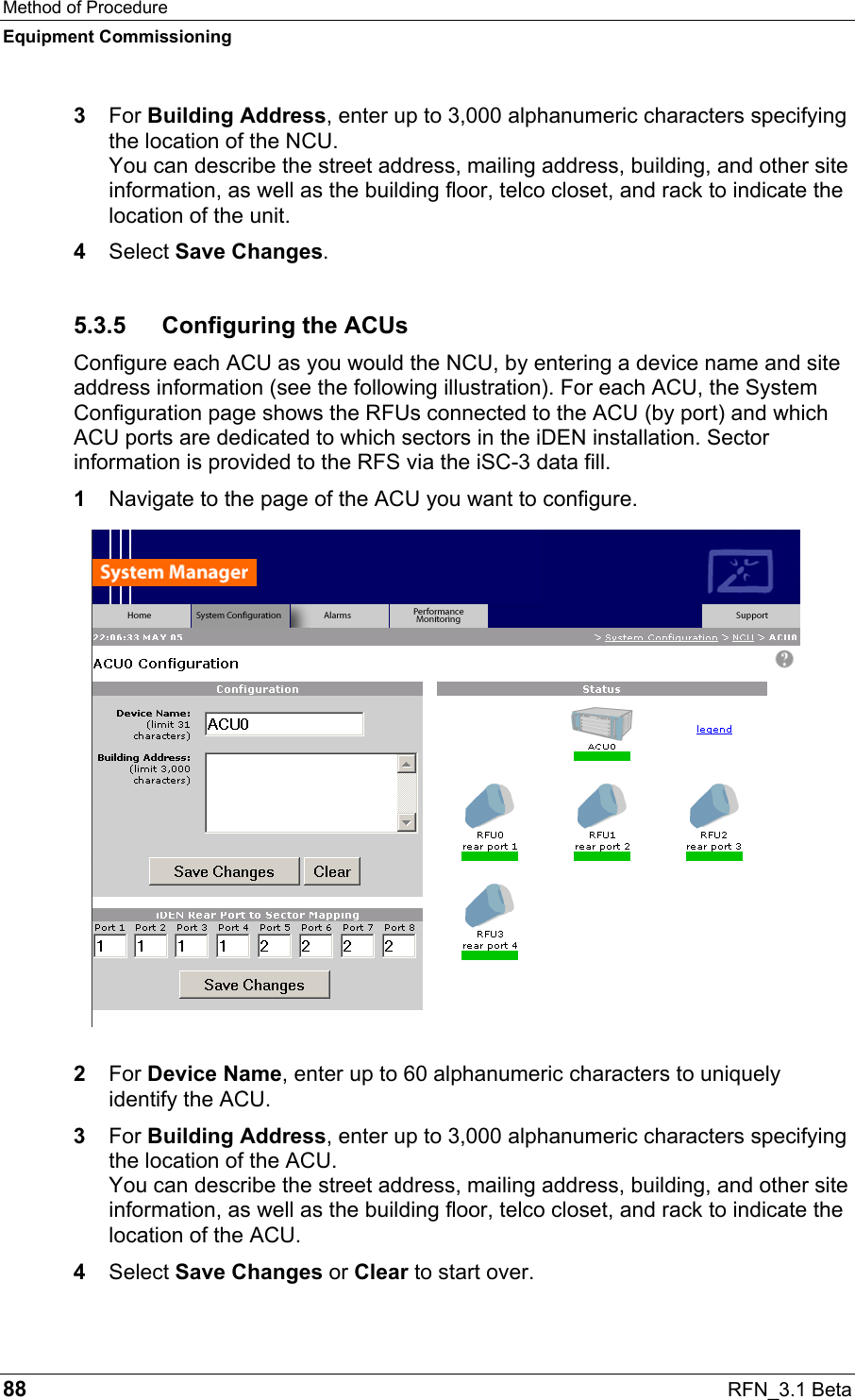
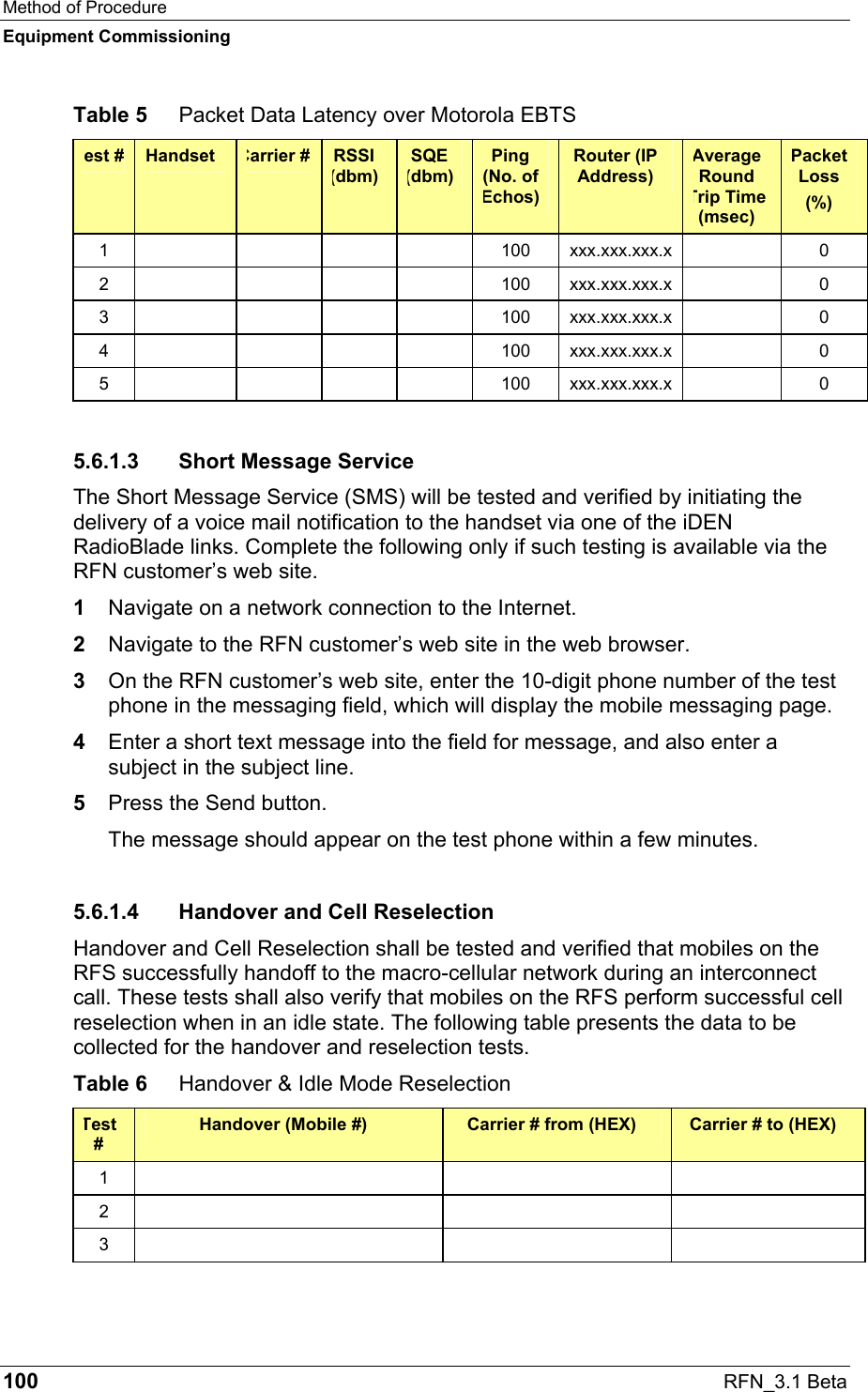
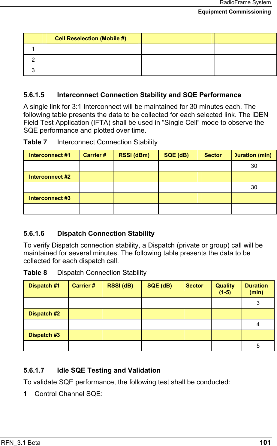
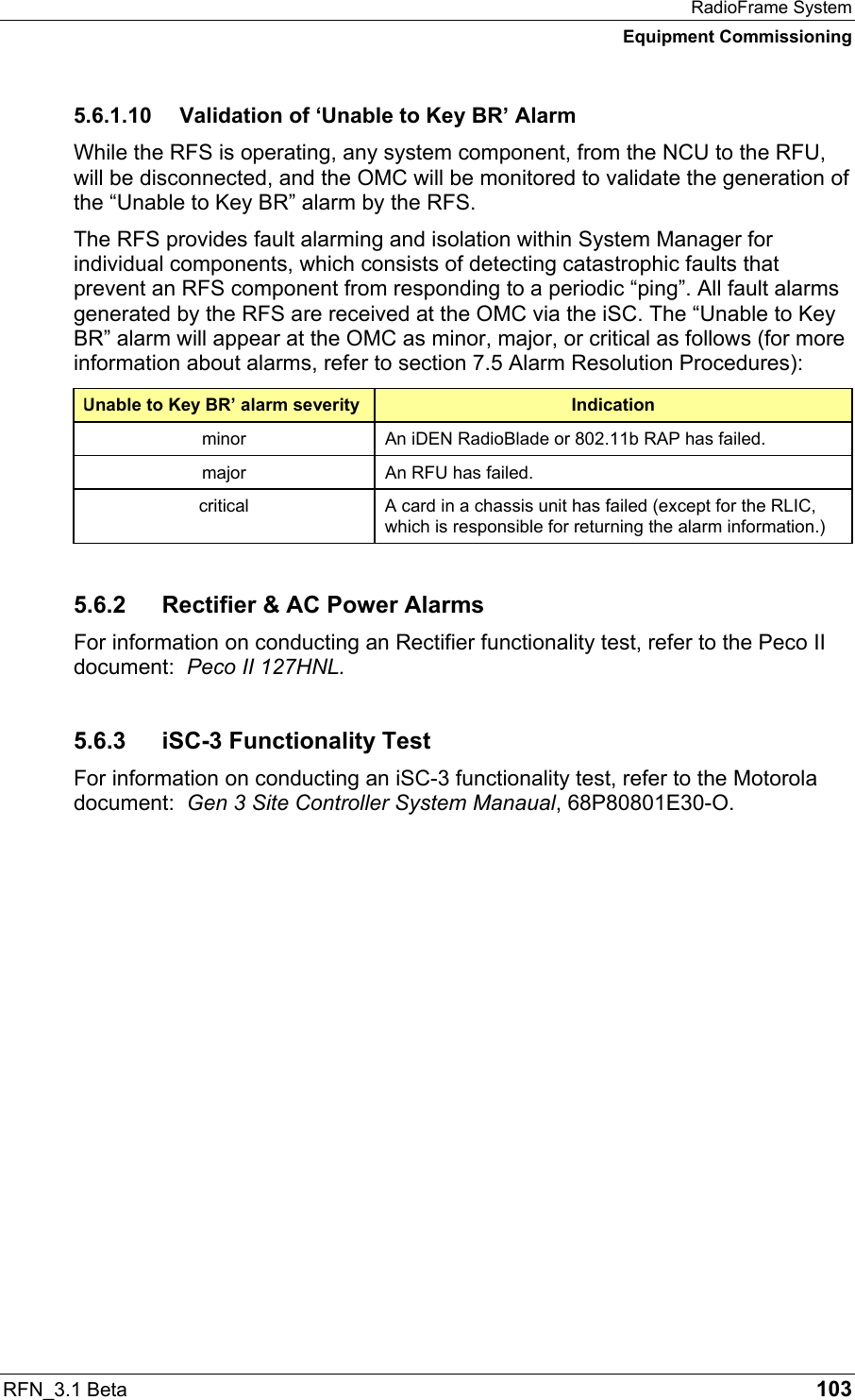
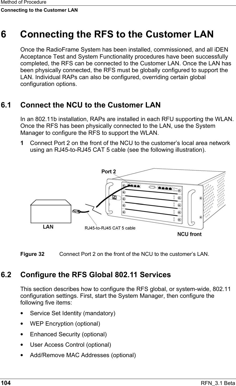
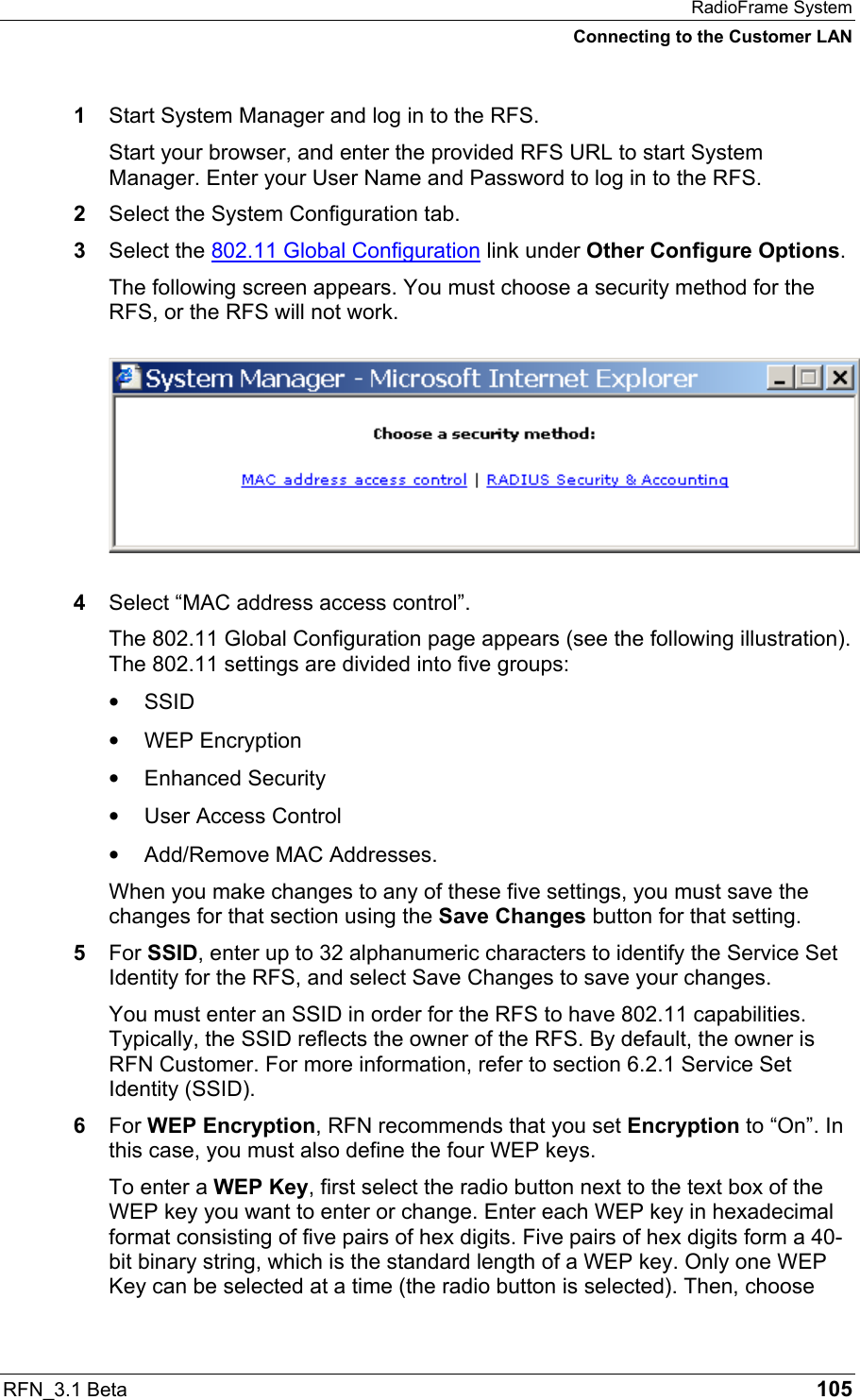
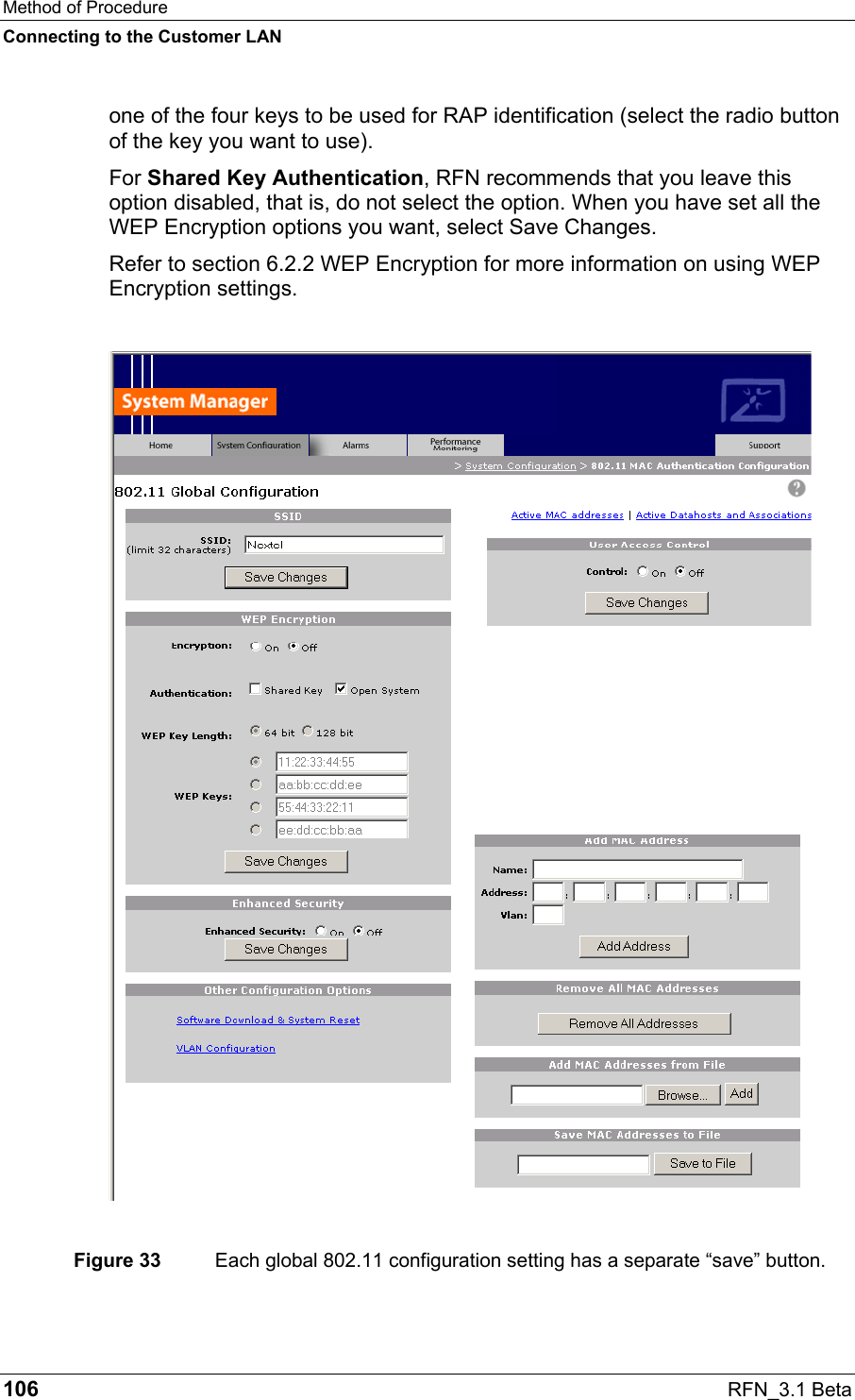
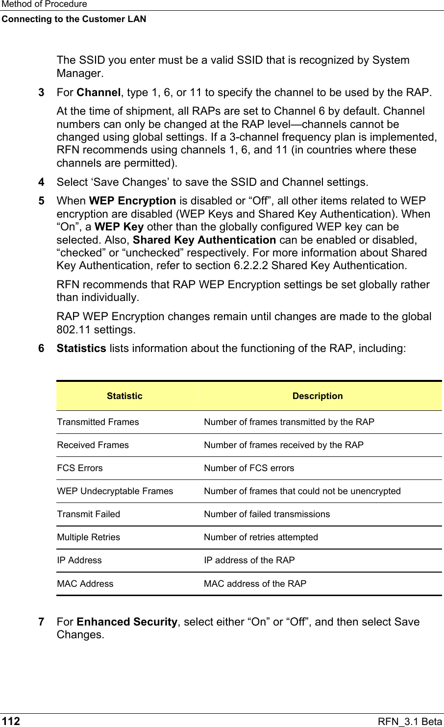
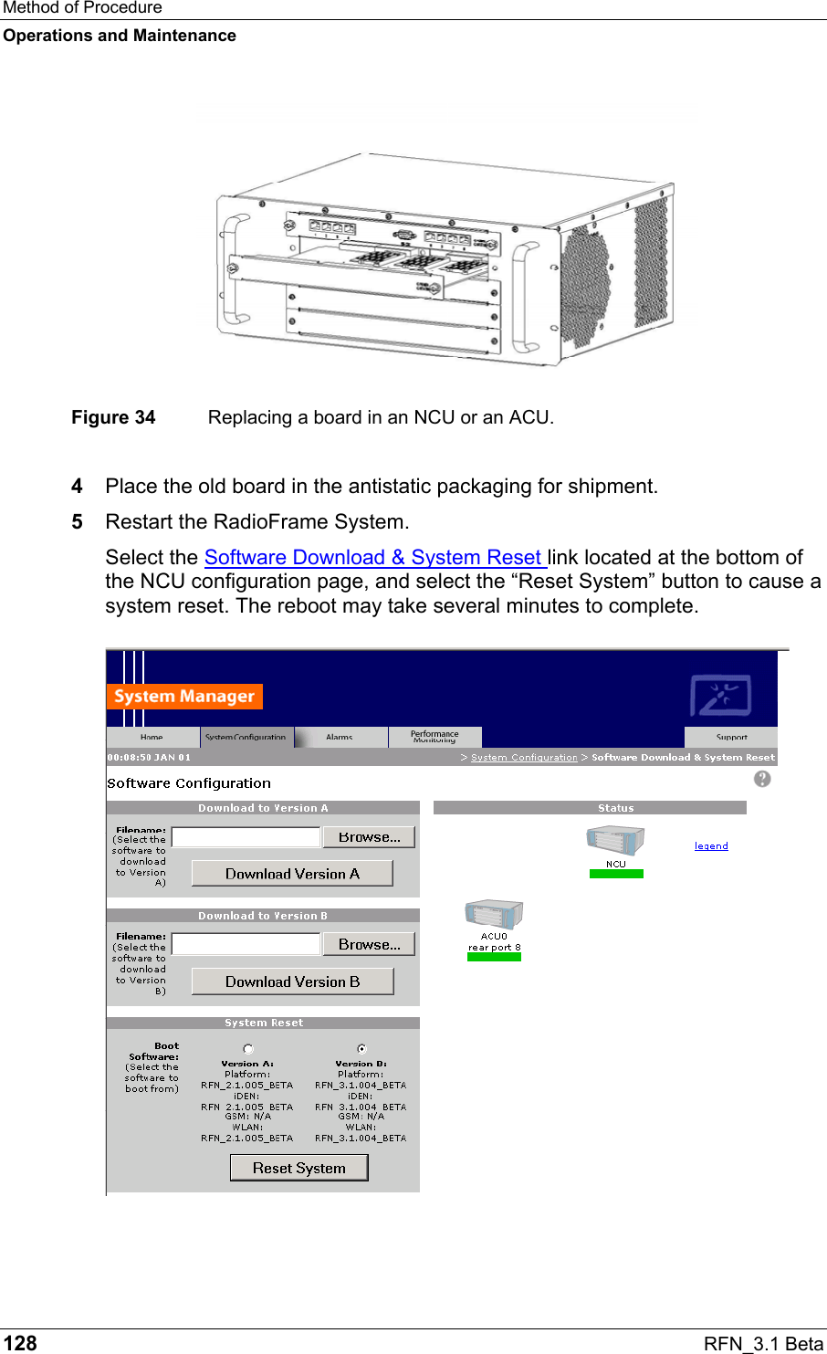
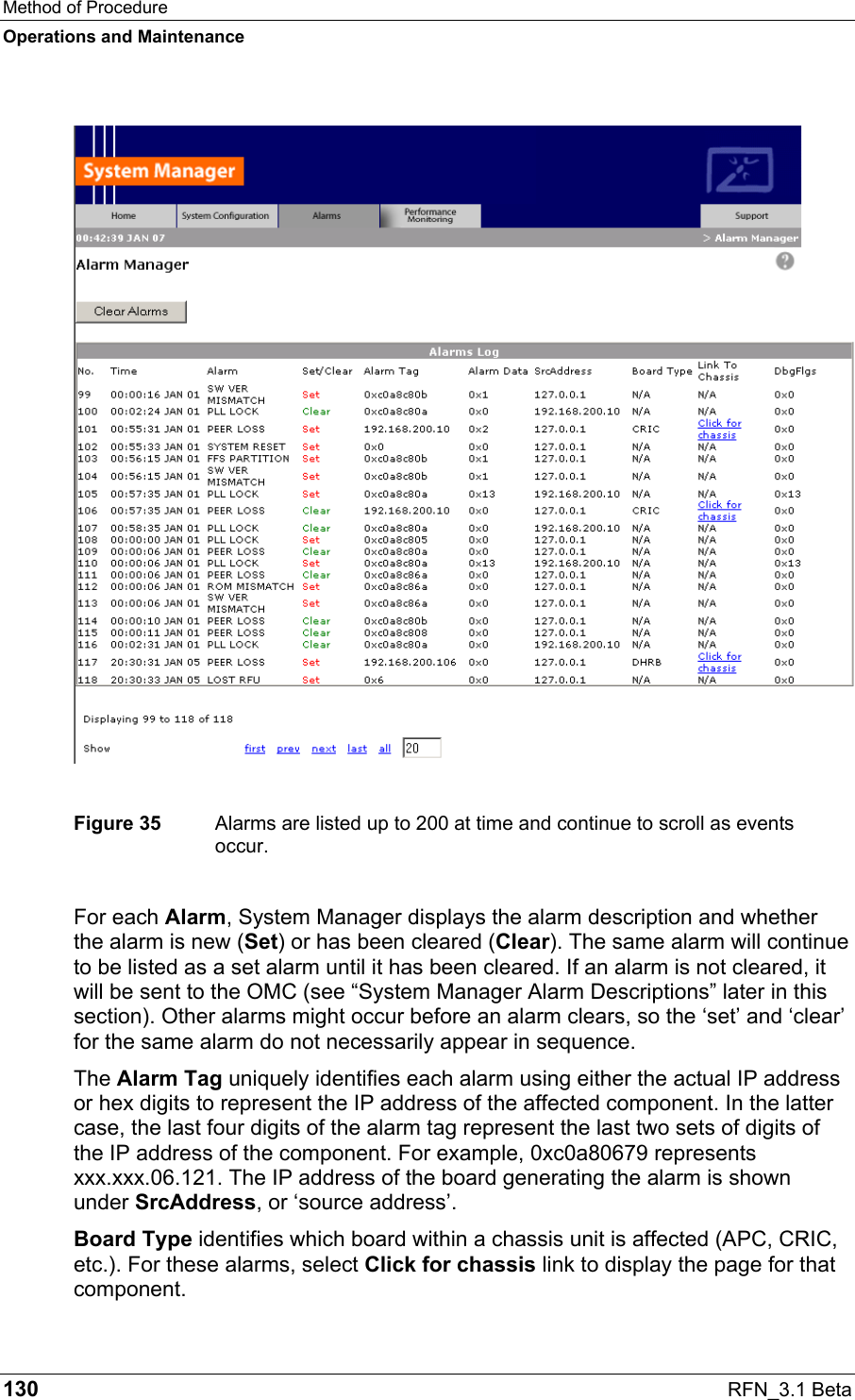
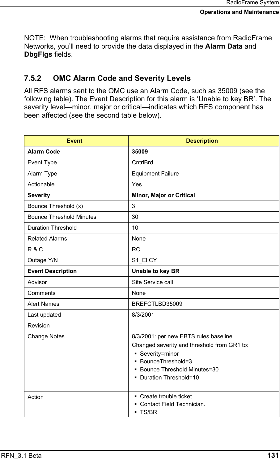
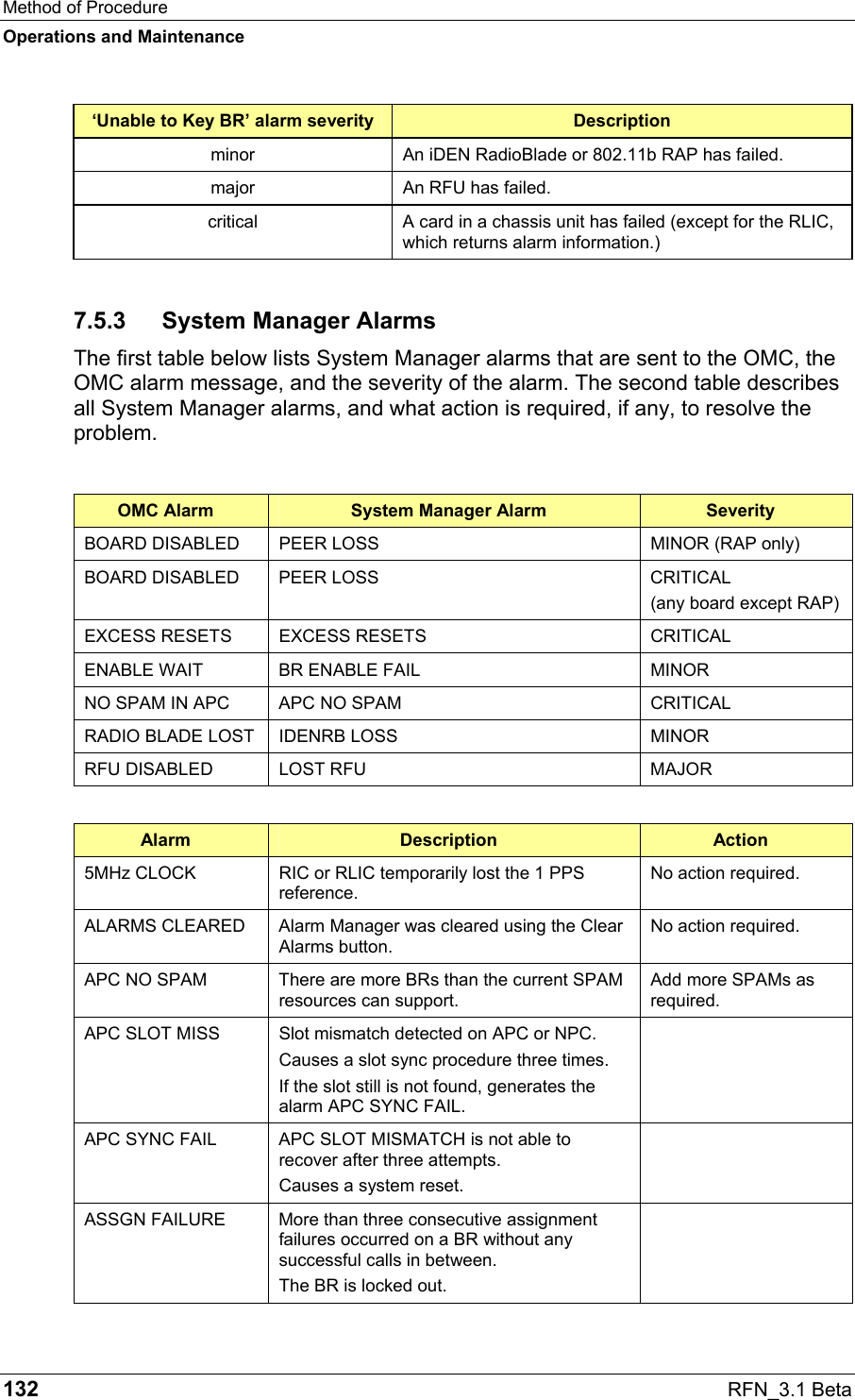
![RadioFrame System Pre-Installation RFN_3.1 Beta 35 System Unit Weight iSC-3 (2) EAS CSU Power Plant Rectifier 72 lbs (Power Plant 58 lbs) + (two Rectifiers at 7 lbs ea.) Battery 600 lbs (eight batteries at 75 lbs each) 3.3.4 Power System Unit Power RadioFrame System NCU 100-240 Volts AC, 47-63 Hz, 8-3.5A, or Negative 52.5 ±.5 Volts DC, 11A ACU 100-240 Volts AC, 47-63 Hz, 8-3.5A, or Negative 52.5 ±.5 Volts DC, 11A iDEN Interface iSC-3 (1) Negative 40-60 Volts DC; 1.5 A iSC-3 (2) Negative 40-60 Volts DC; 1.5 A EAS Negative 40-60 Volts DC CSU Negative 40 Volts DC Power Plant Rectifier Input Voltage 85 to 265 VAC (continuous) 45 to 70 Hz Current 12 Amp maximum The rectifier’s micro-controller adjusts the output current to limit the input current to allow each rectifier to be plugged into a standard 115/230 VAC @ 15 Amp IEC outlet. Power Factor >90% for 20% to 100% loads Output Voltage 50.00 to 60.00 VDC 52.5 VDC Factory Set (default) Regulation ± 1.0% (includes output o-ring diode) Overvoltage 50.00 to 60.00 VDC 57.00 VDC Factory Set (default) RED [FAIL] LED indication and shuts down rectifier providing output current. Noise <32 dBmC (voice frequency) <100 millivolts-RMS (wide band) <250 millivolts peak-to-peak](https://usermanual.wiki/RadioFrame-Networks/DH2/User-Guide-363493-Page-47.png)