RadioFrame Networks MCSERIESSC MC Series Standard Capacity Base Station User Manual BOOK std cap
RadioFrame Networks, Inc MC Series Standard Capacity Base Station BOOK std cap
UserManual.wiki
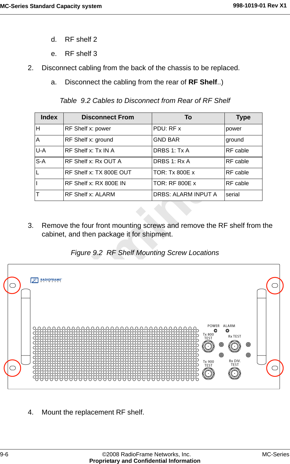
>
RadioFrame Networks
>
MCSERIESSC User Manual
User Manual
Navigation menu
Upload a User Manual
Namespaces
Wiki Guide
HTML
PDF
Info
Views
User Manual
Discussion / Help
Navigation


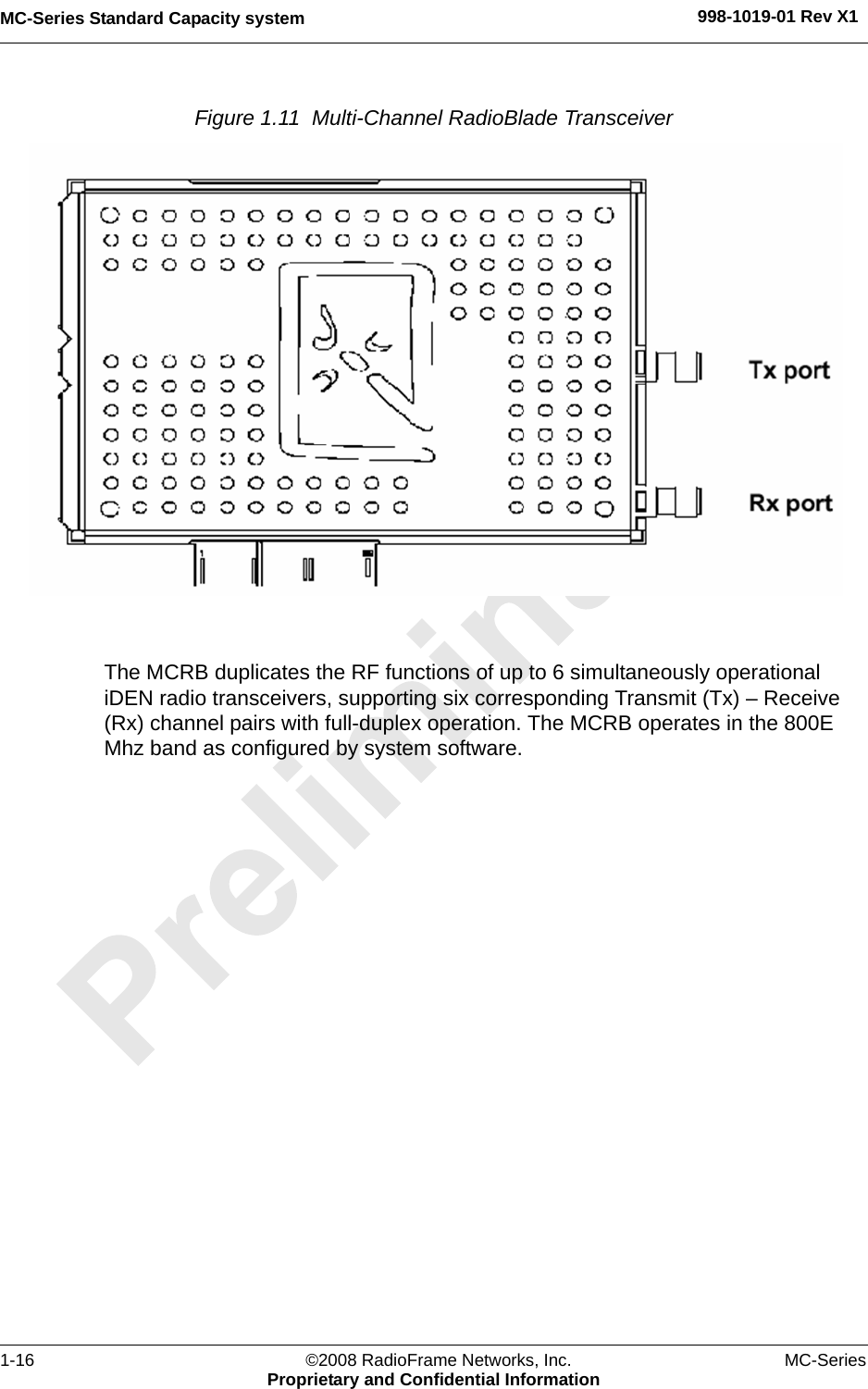
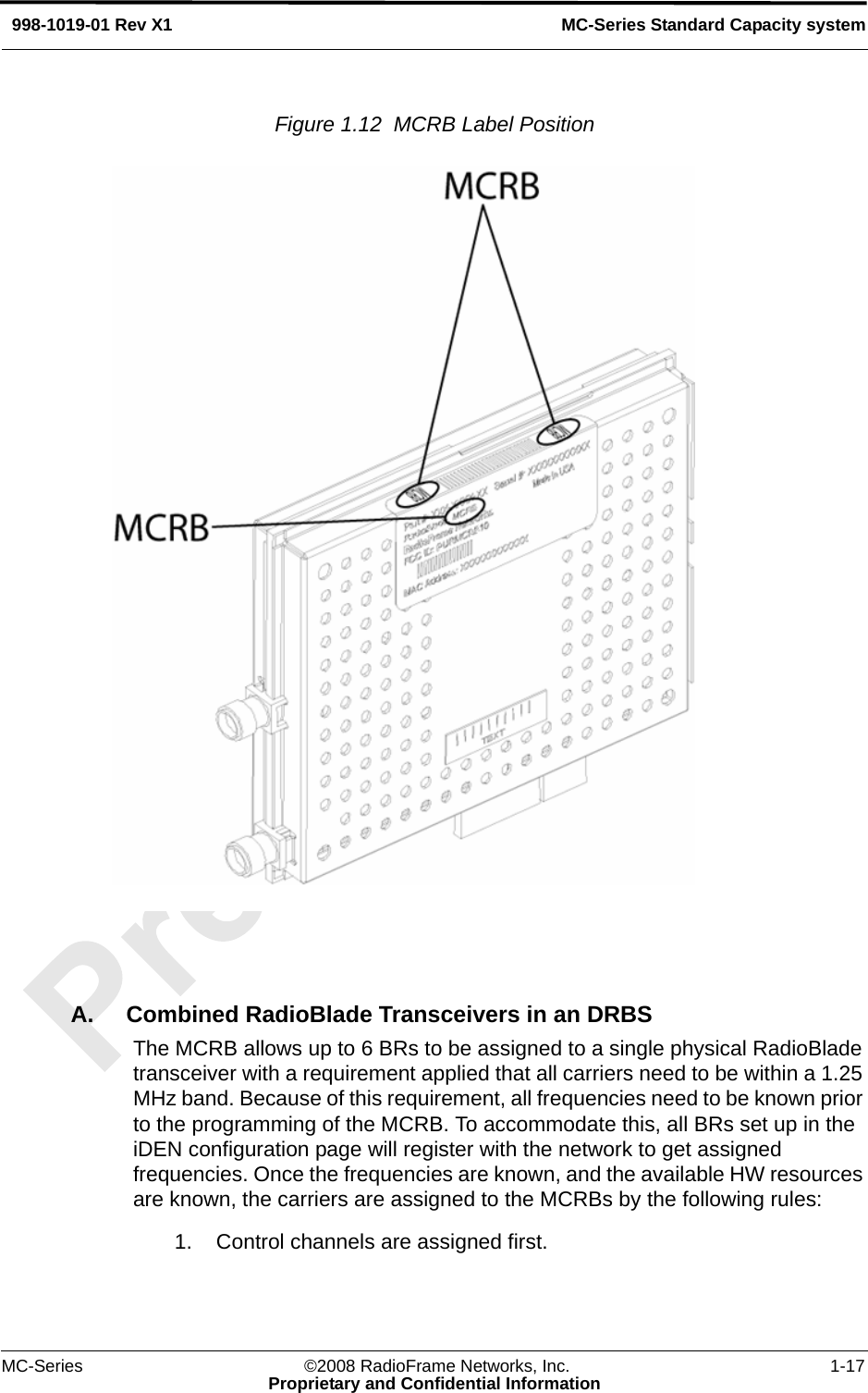
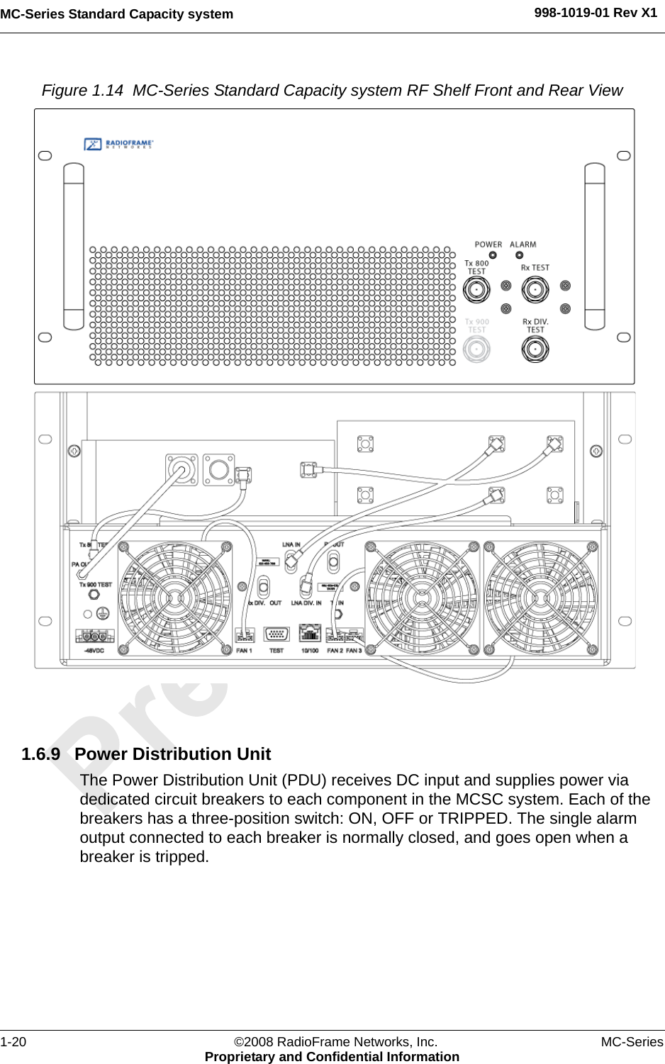

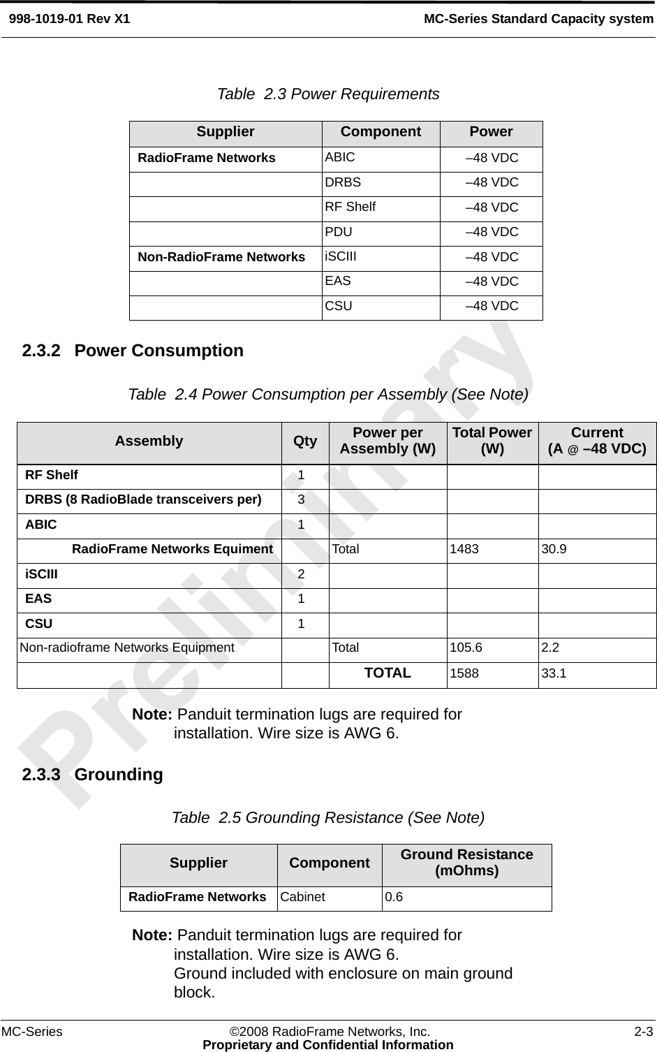
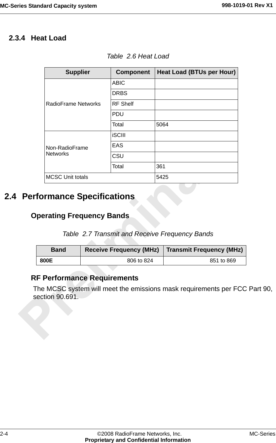
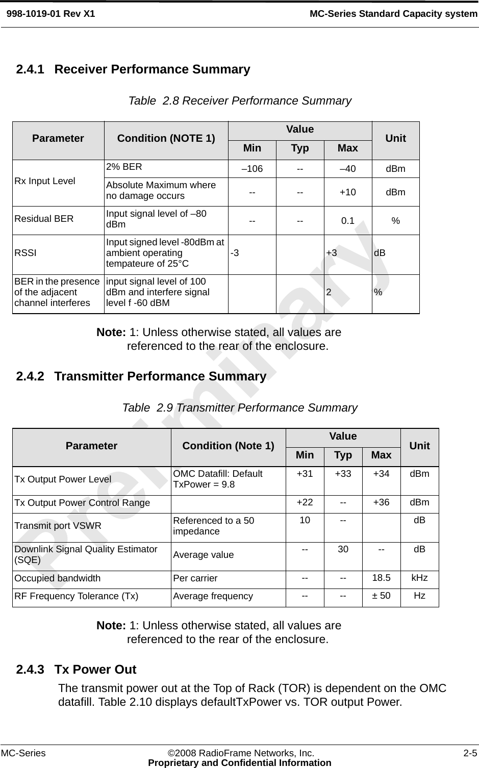
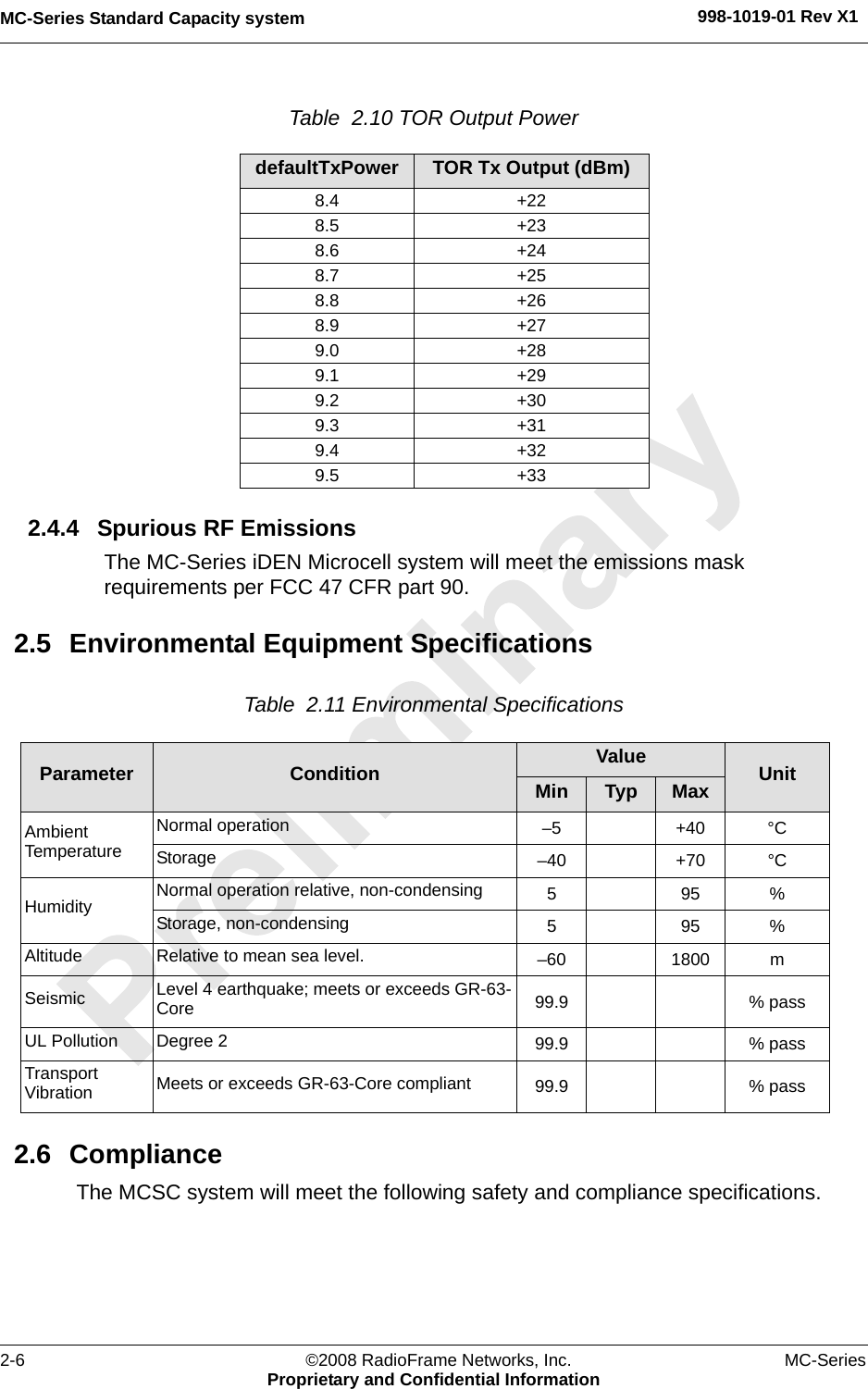

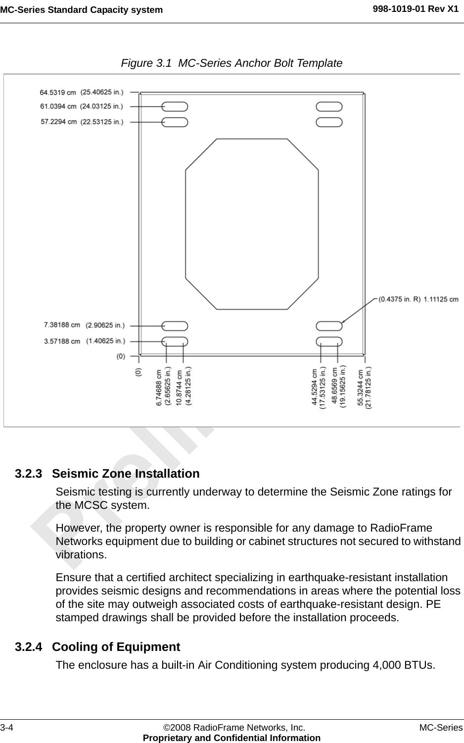
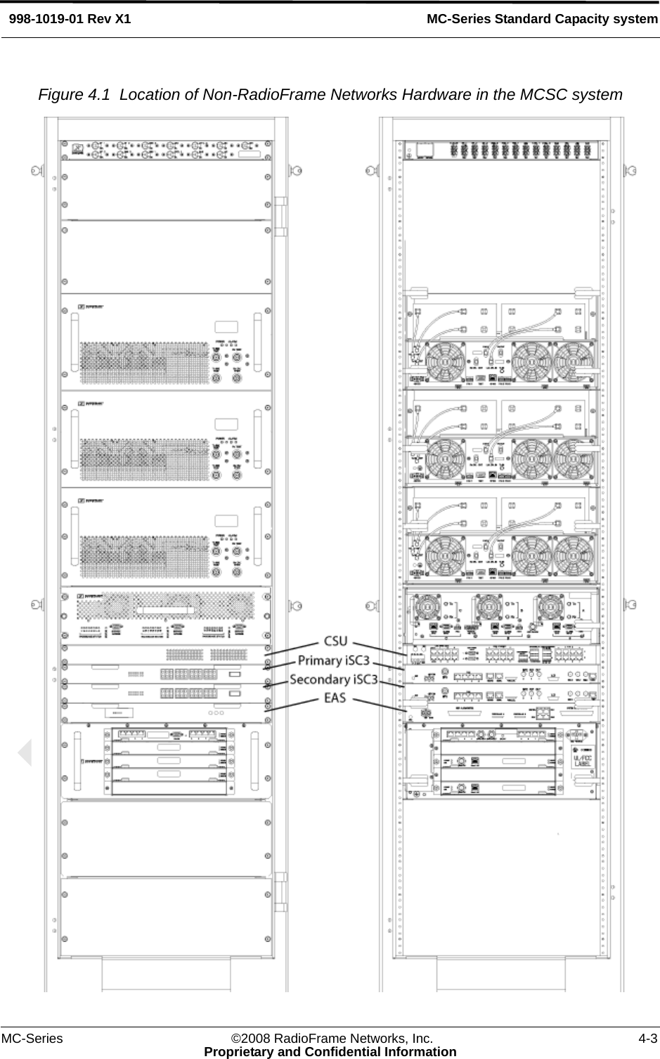
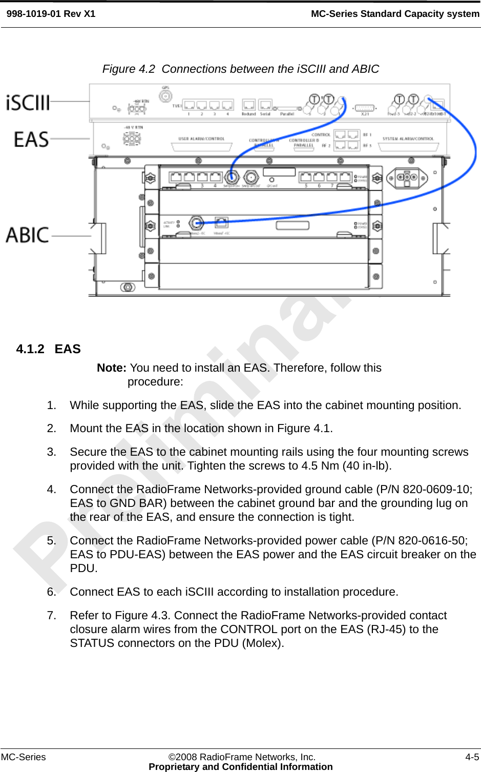
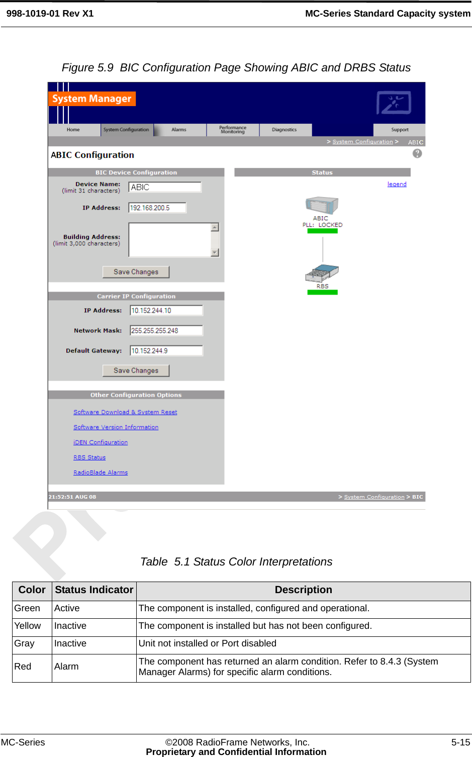
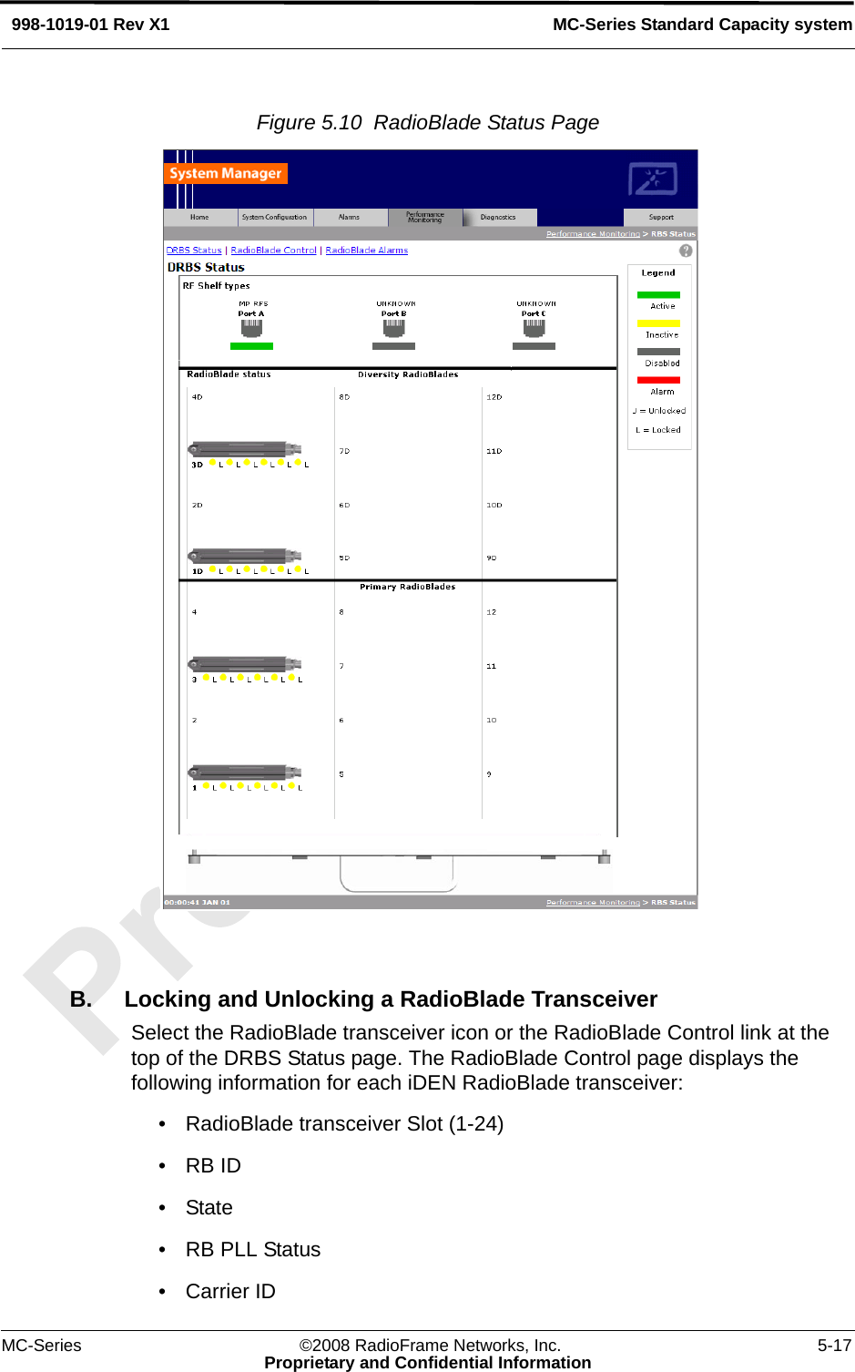
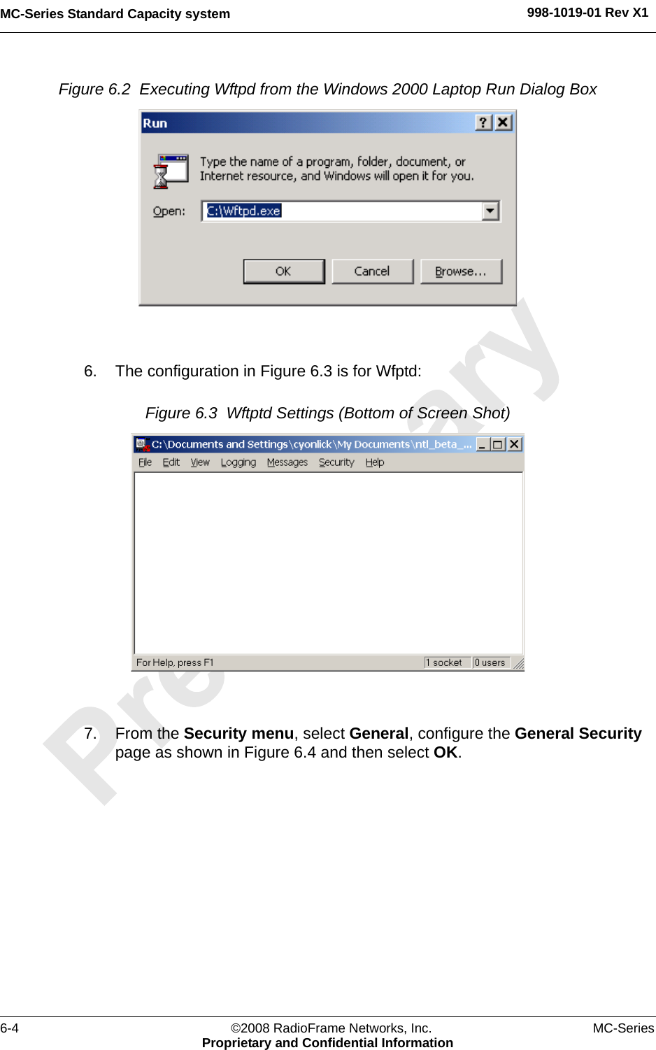
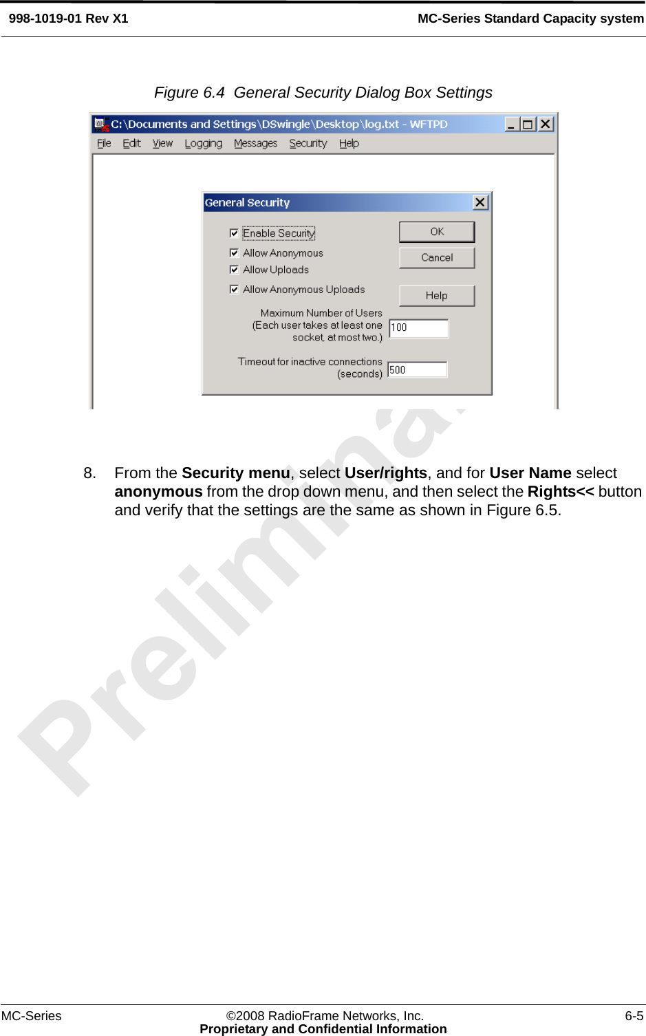
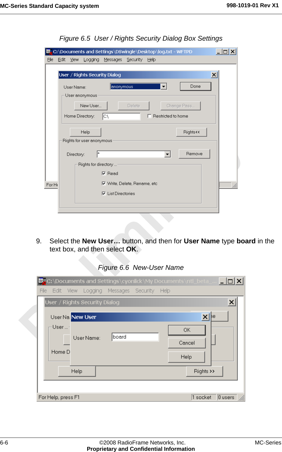
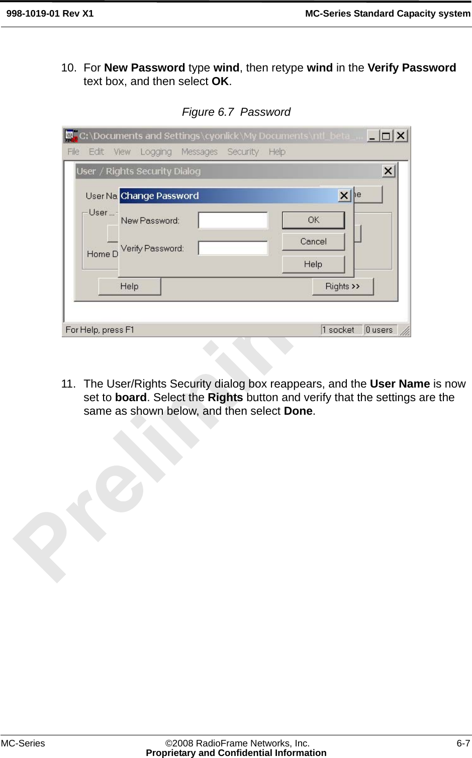
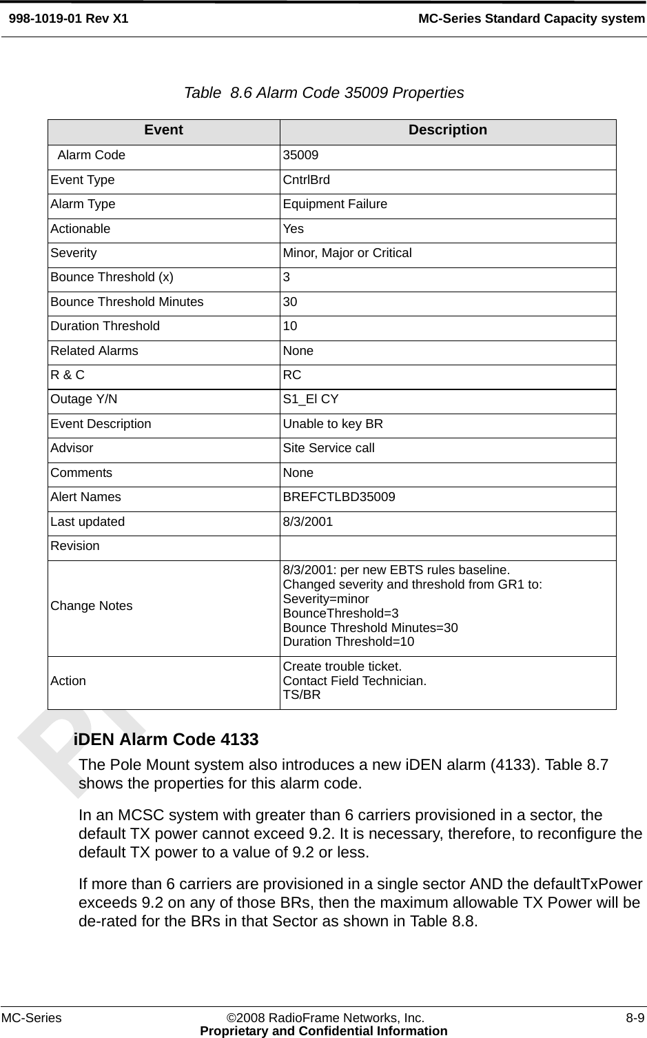
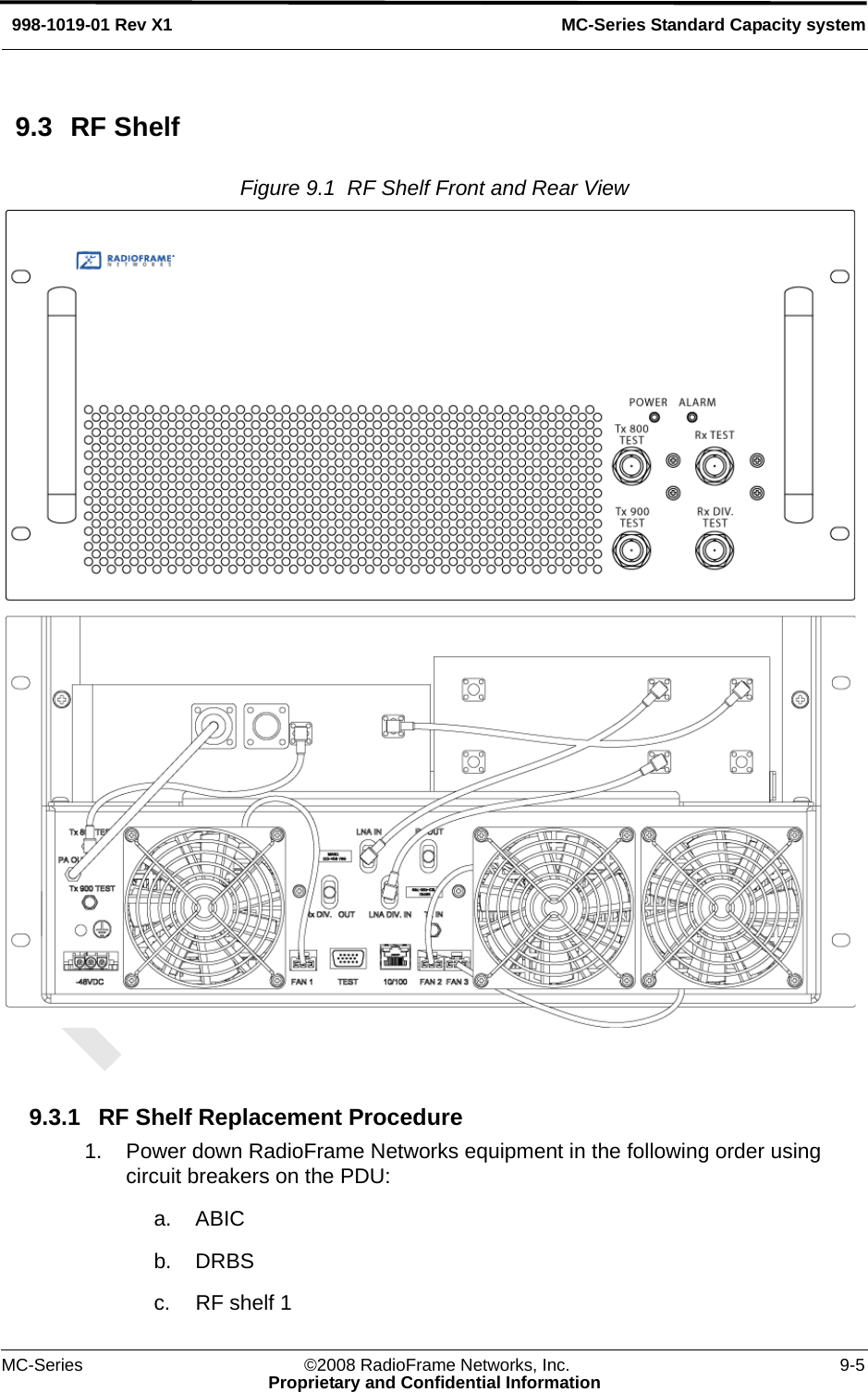
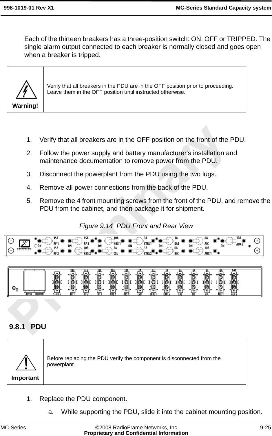
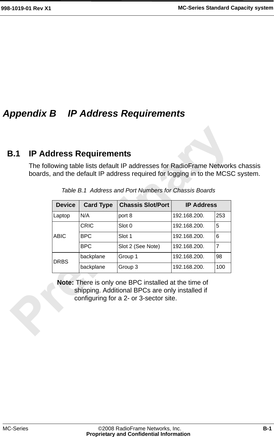
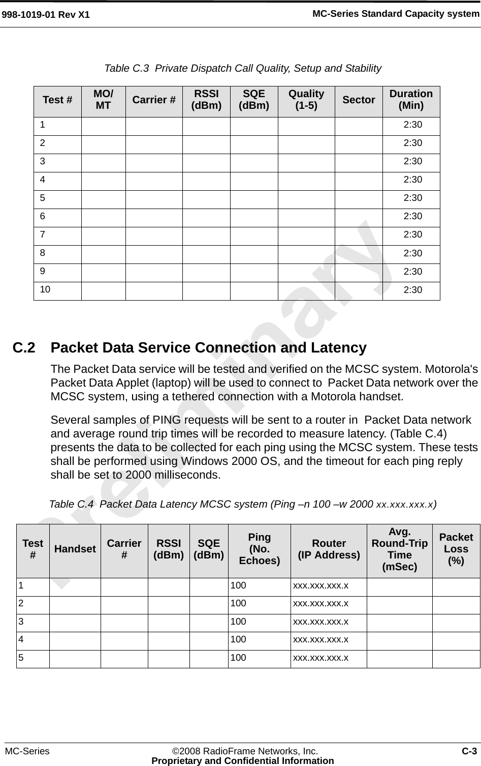
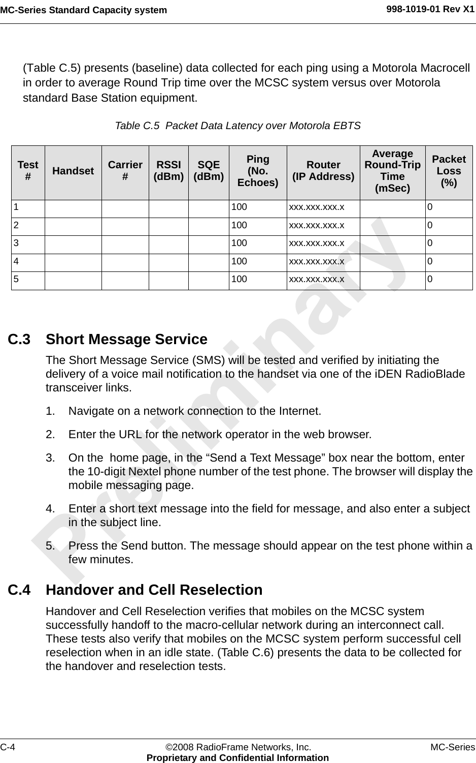
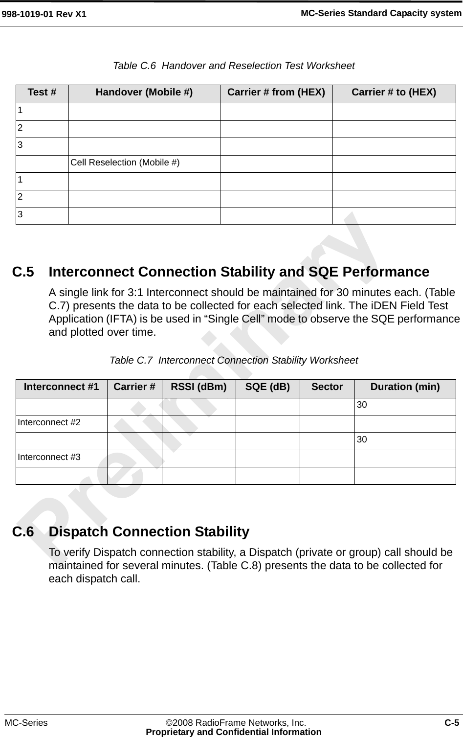
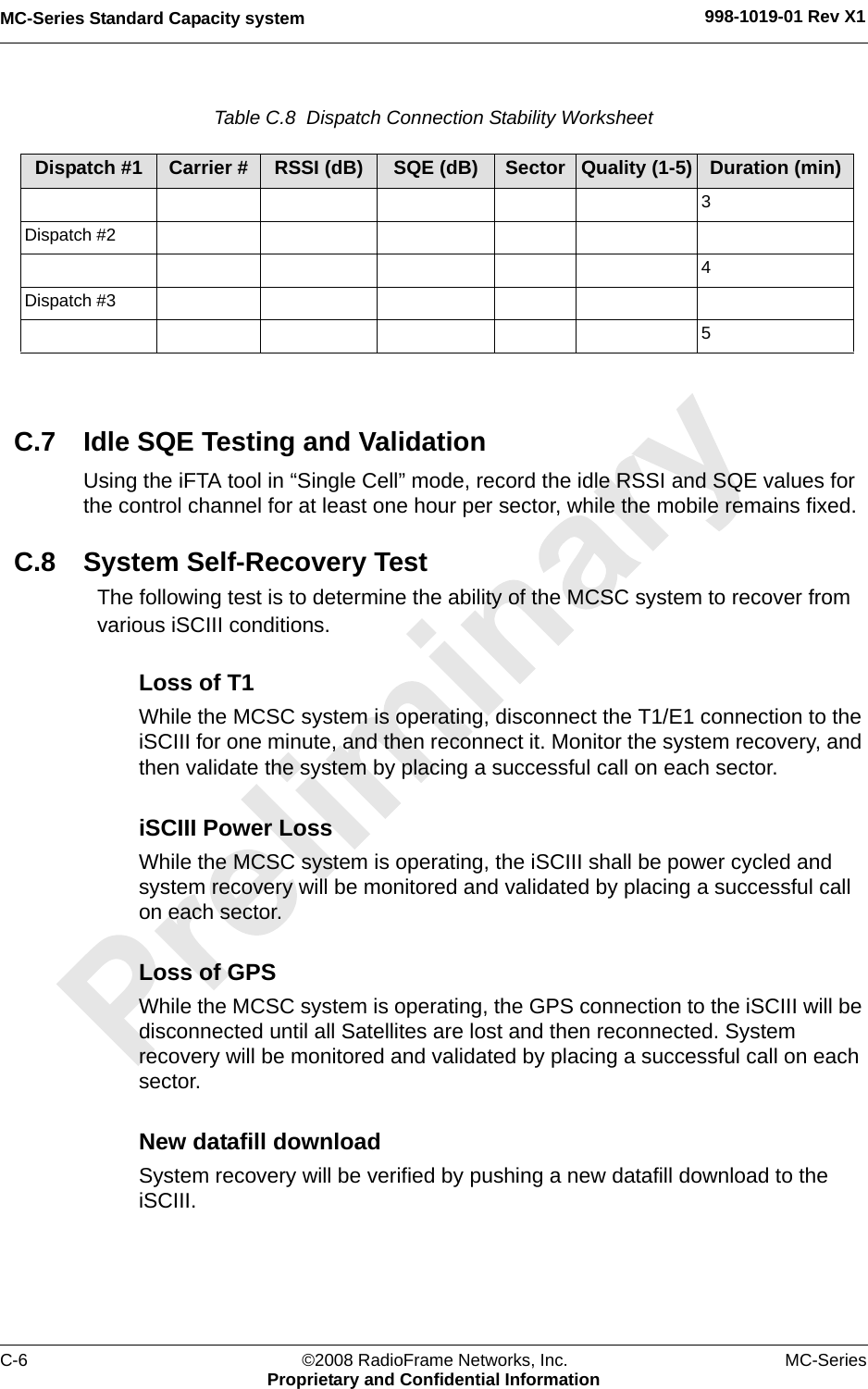
![MC-Series Standard Capacity system 998-1019-01 Rev X14-4 ©2008 RadioFrame Networks, Inc. MC-SeriesProprietary and Confidential Information4.1.1 iSCIII Note: The iSCIII does not come pre-installed with the MCSC system. Therefore, follow this procedure to install the component.1. While supporting the iSCIII, slide the iSCIII into the cabinet mounting position.2. Mount the iSCIII in the location shown in Figure 4.1. If necessary, install side rails in the mounting position in the cabinet.3. Secure the iSCIII to the cabinet mounting rails using the four mounting screws provided with the unit. Tighten the screws to 4.5 Nm (40 in-lb).4. Connect the RadioFrame Networks-provided ground cable (P/N 820-0609-10; ISC1 to GND BAR) between the cabinet ground bar and the grounding lug on the rear of the iSCIII, and ensure the connection is tight. 5. Connect the RadioFrame Networks-provided power cable (P/N 820-0613-50; PDU-CTRL_1 to ISC1) between the iSCIII power and the CTRL1 circuit breaker on the PDU. 6. Connect the RadioFrame Networks-provided ground cable (P/N 820-0609-10; ISC1 to GND BAR) between the cabinet ground bar and the grounding lug on the rear of the iSCIII, and ensure the connection is tight. 7. Connect the iSCIII according to installation procedure.8. Refer to Figure 4.2. Using the RadioFrame Networks-provided coax cable (P/N 111-0001-02;ABIC-ERTM 5 MHz IN to iSCIII REF OUT-1), connect the iSCIII port SITE REF OUT 1 [K] to the ABIC ERTM port 5 MHz IN [L]. 9. Terminate the two remaining SITE REF OUT ports on the iSCIII.10. Using the RadioFrame Networks-provided coax cable (PN 111-0001-02; ABIC-CRTC to iSC1 REF OUT-1), connect the iSCIII port 10B2-1 to CRTC port 10Base2 iSCIII.11. Terminate the two remaining iSCIII 10B2 ports on the iSCIII.Note: Figure 4.2 does not show all cabling.](https://usermanual.wiki/RadioFrame-Networks/MCSERIESSC/User-Guide-907826-Page-58.png)