Radwin RW2030 Outdoor radio unit operating in 3.65 GHz band User Manual STW
Radwin Ltd. Outdoor radio unit operating in 3.65 GHz band STW
Radwin >
Contents
- 1. Manual part 1
- 2. Manual part 2
- 3. Users manual part 1
- 4. Users manual part 2
- 5. Revised User manual part 2
- 6. Revised User manual part 1
Revised User manual part 2
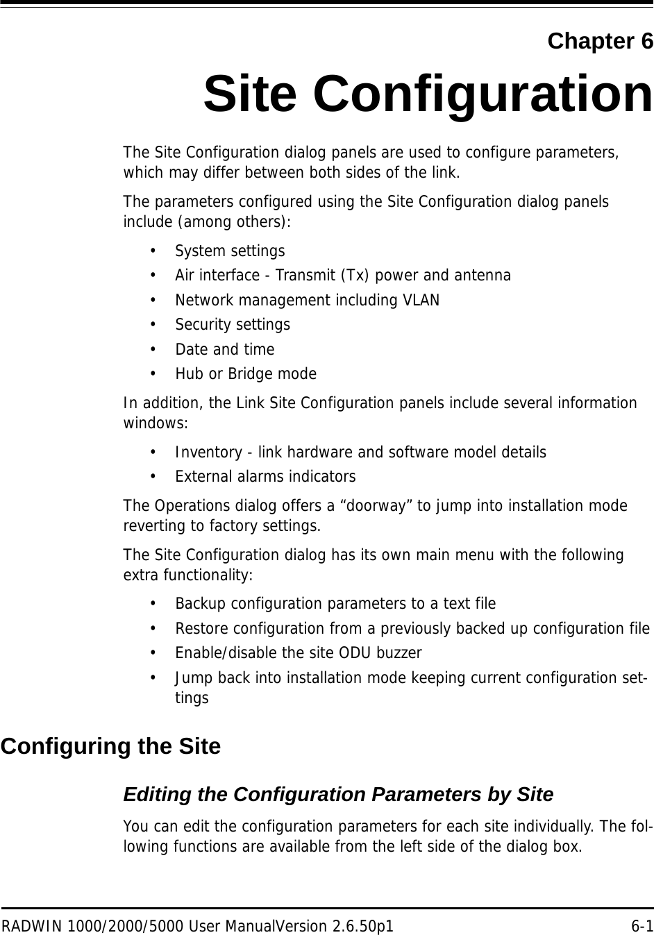
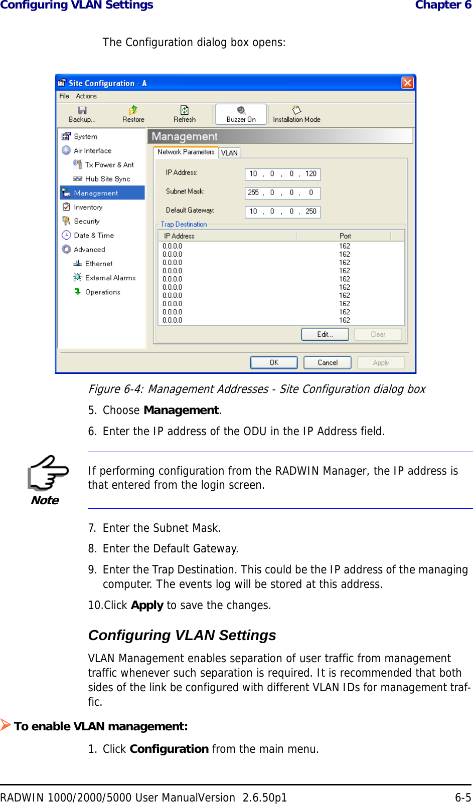
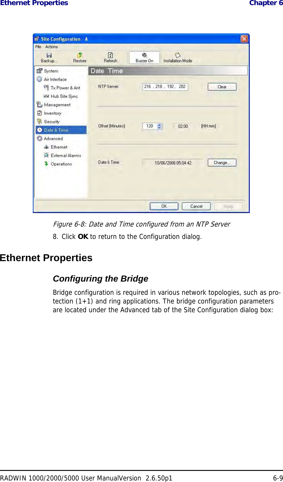
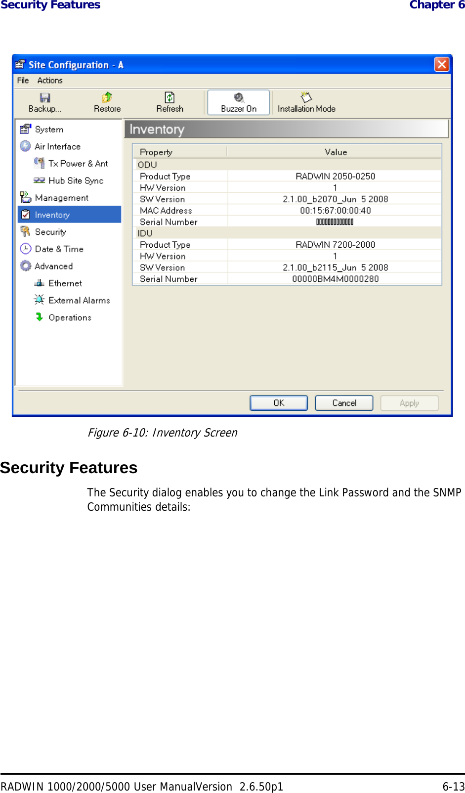
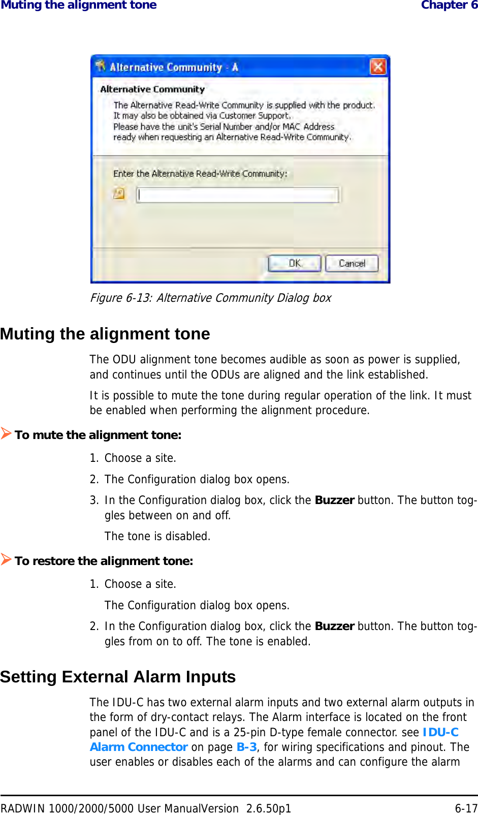
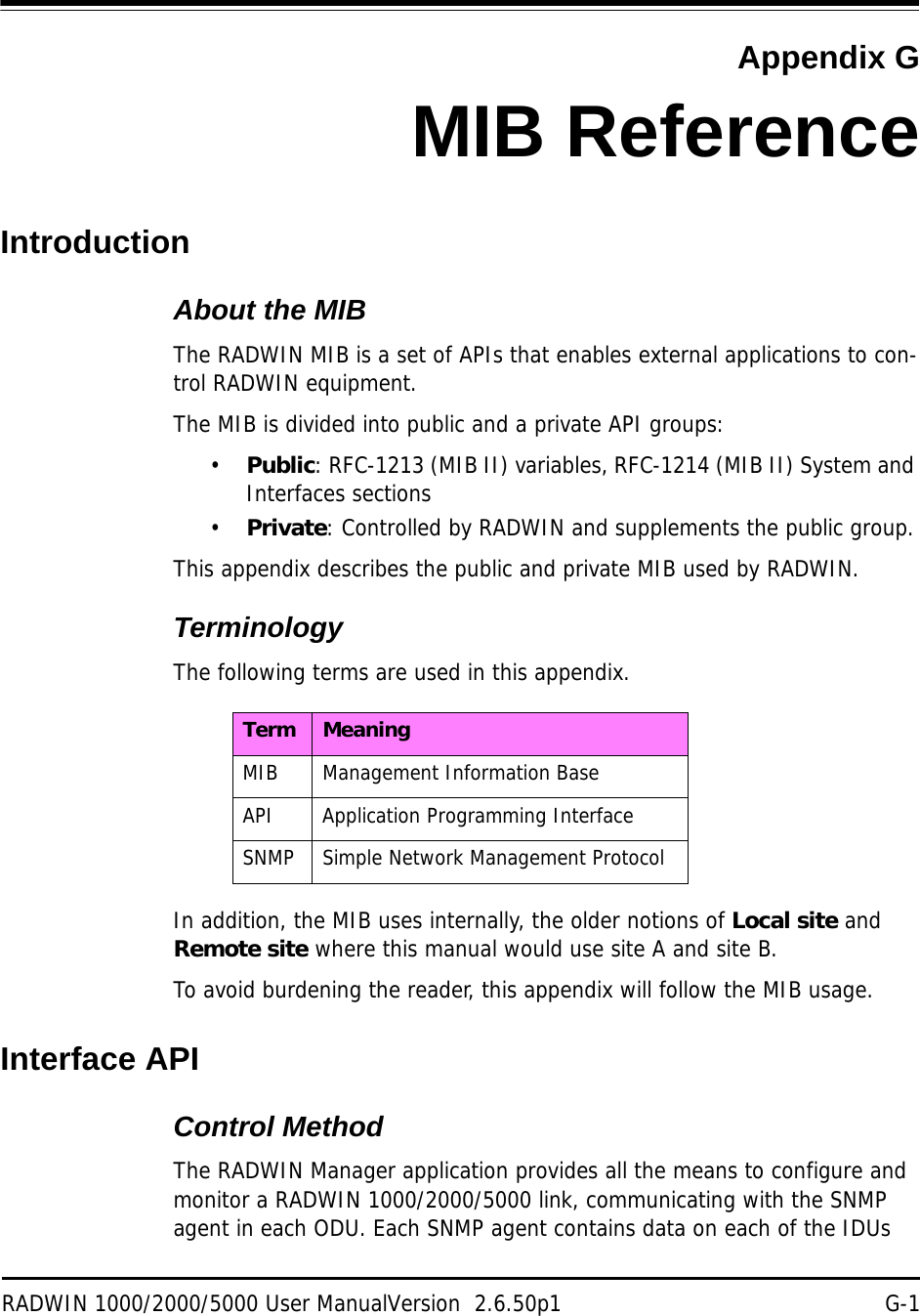
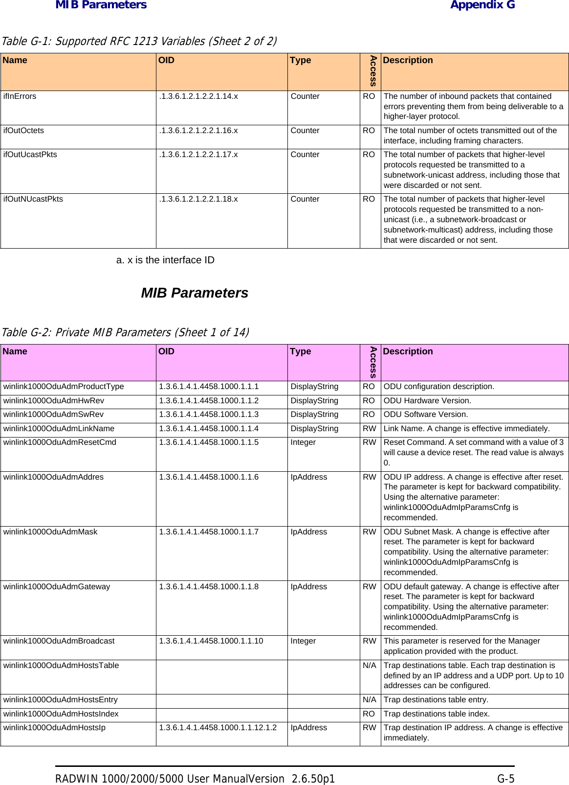
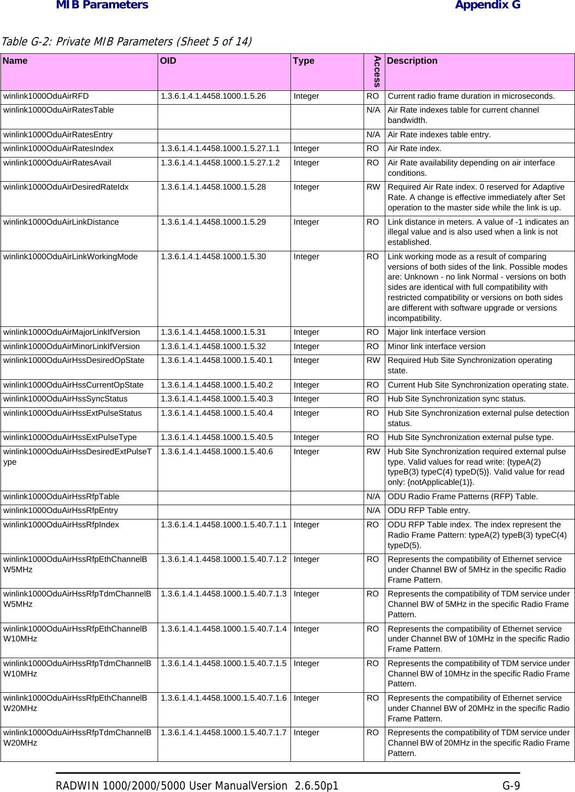
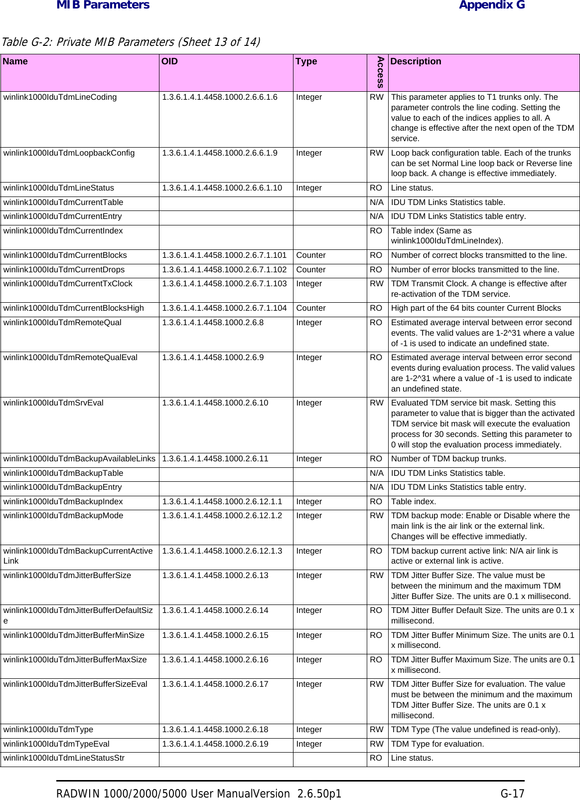
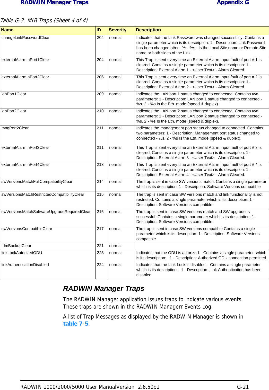
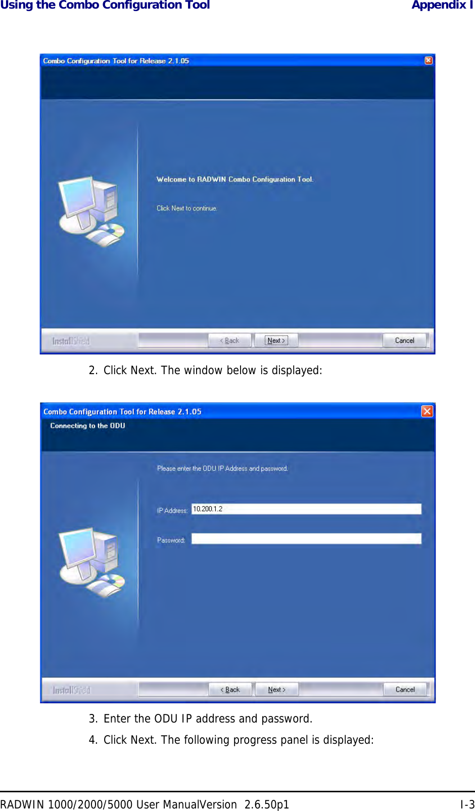
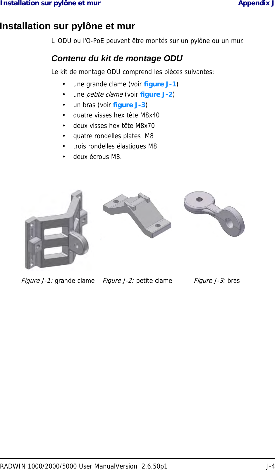
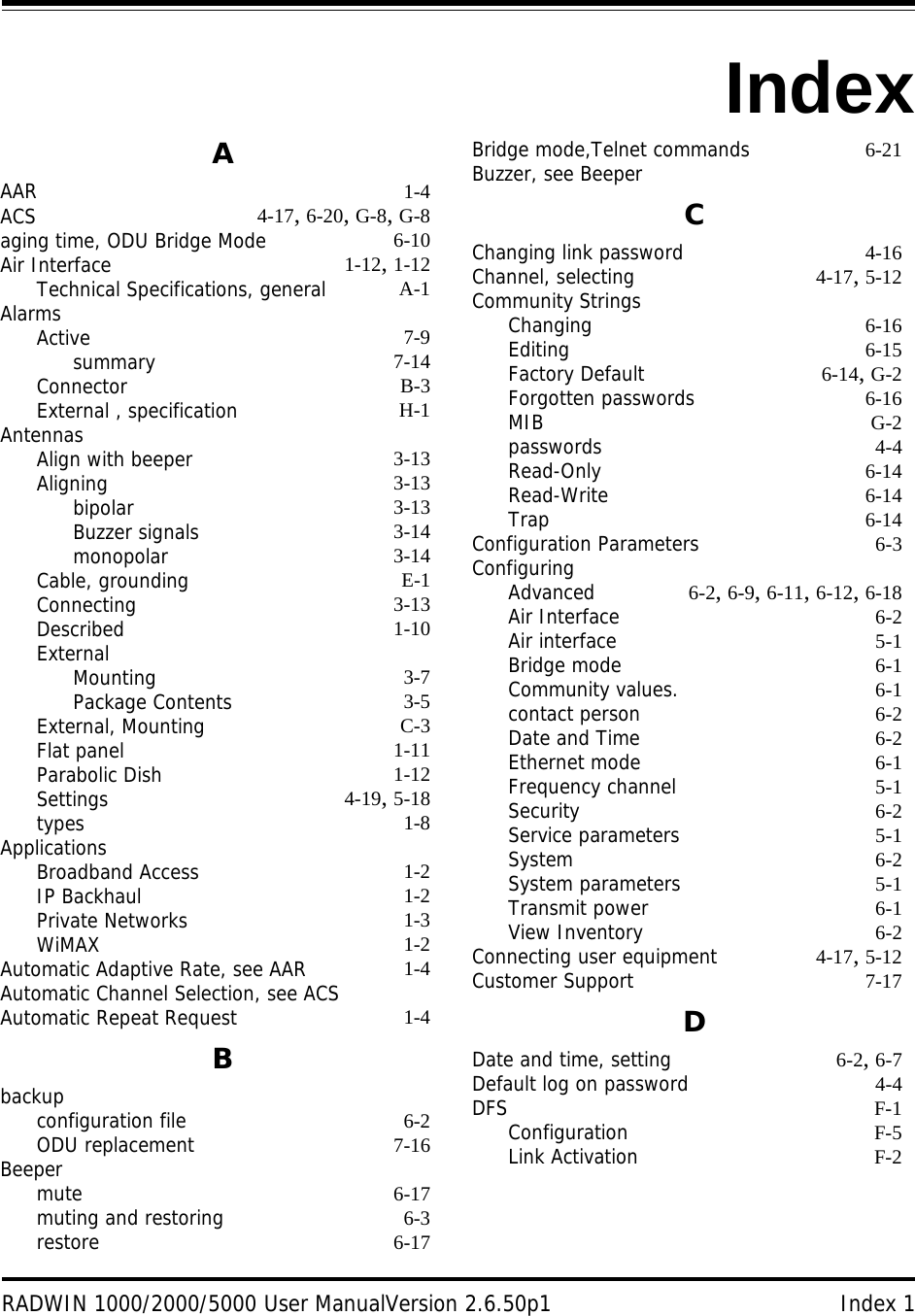
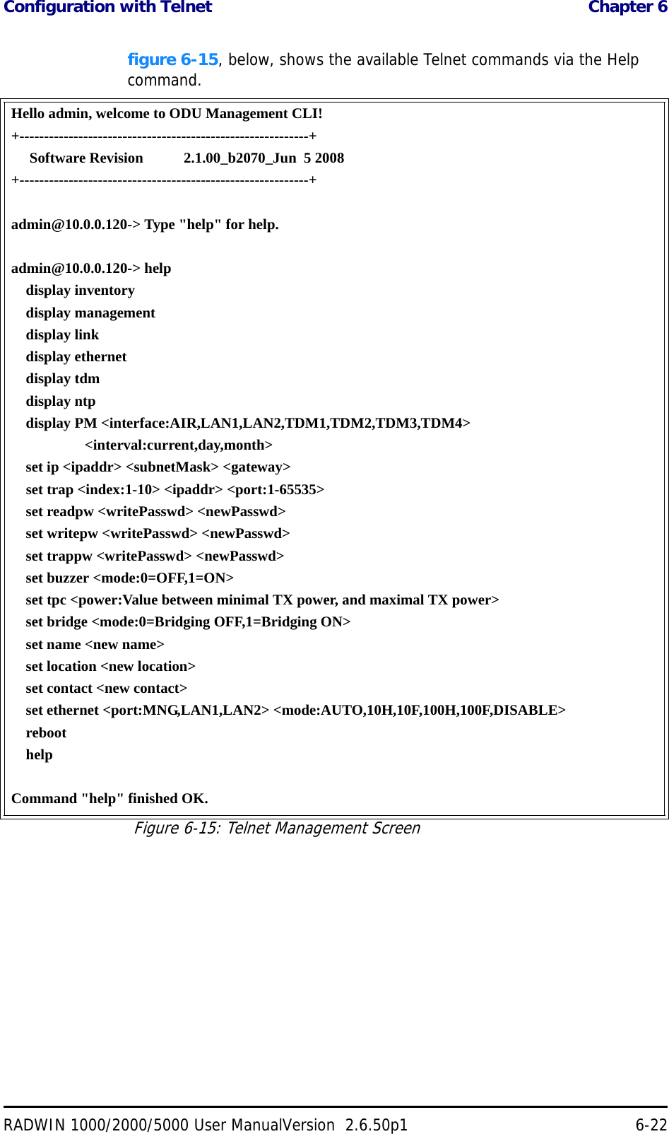
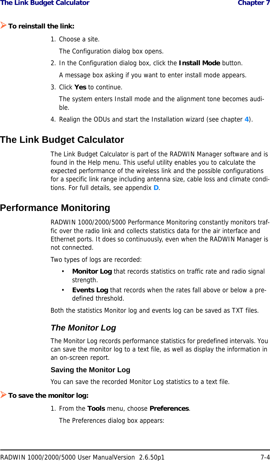
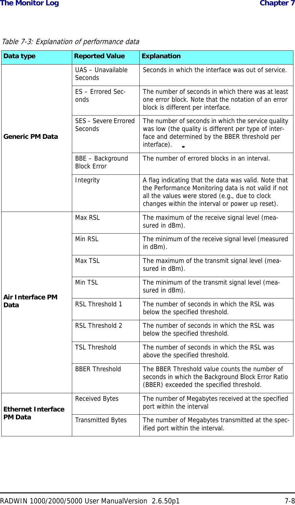
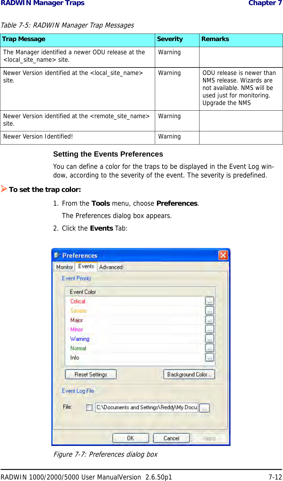
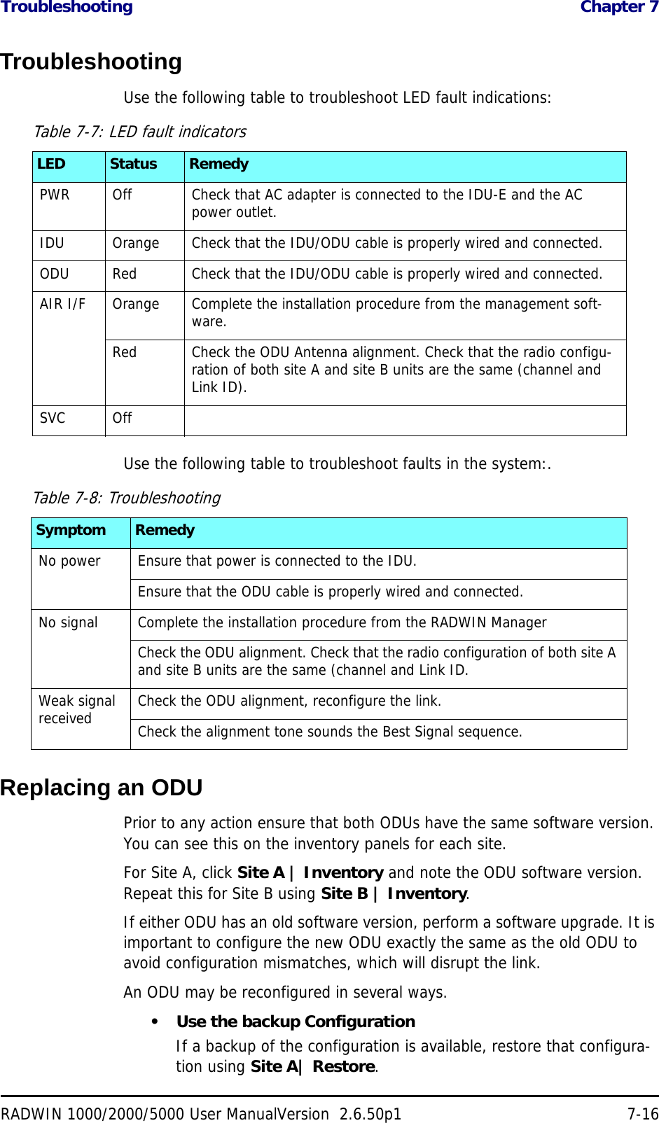
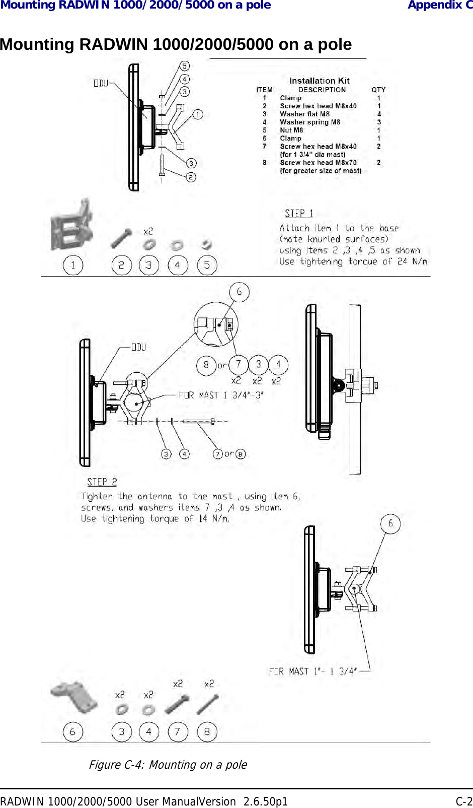
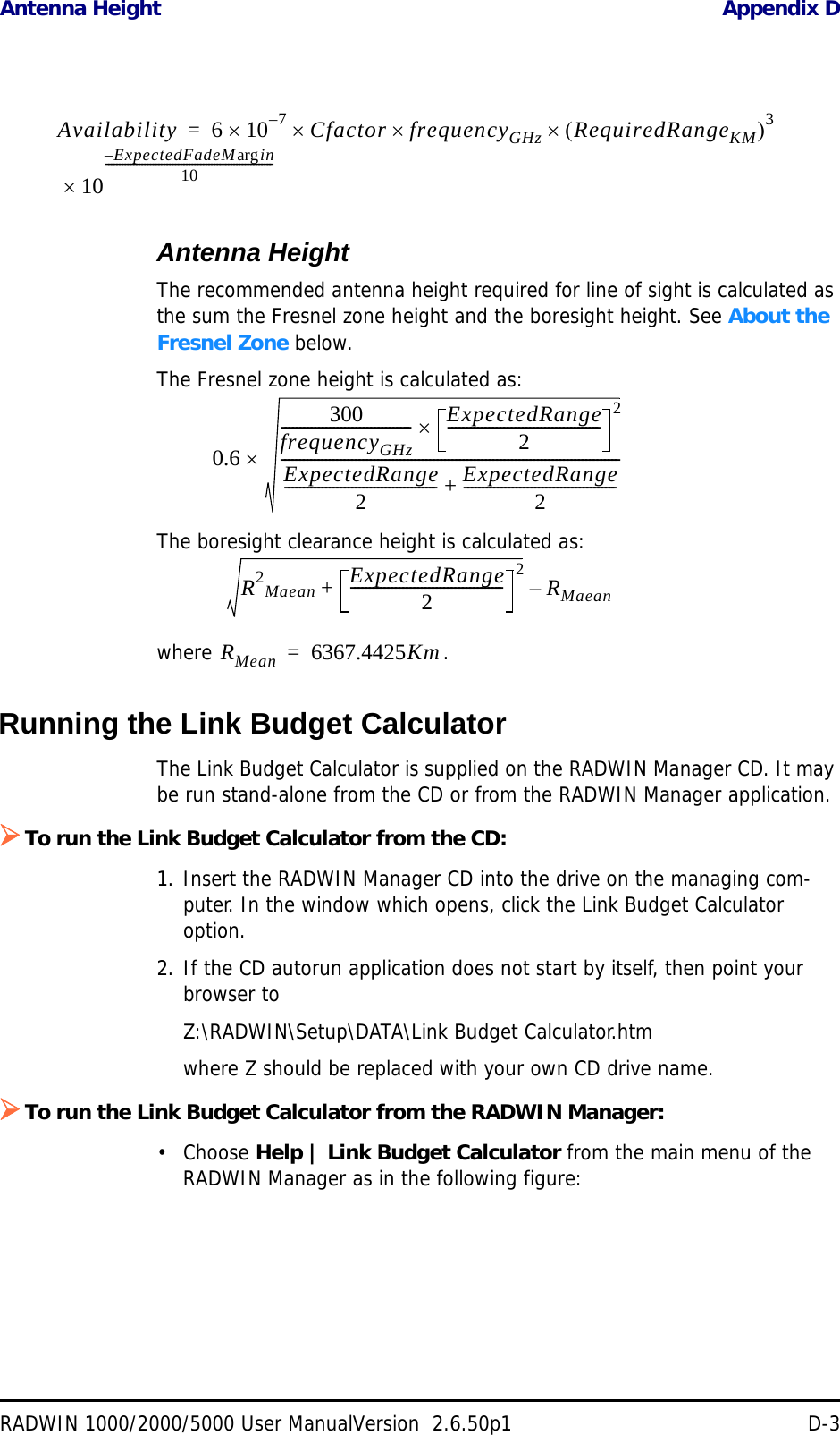
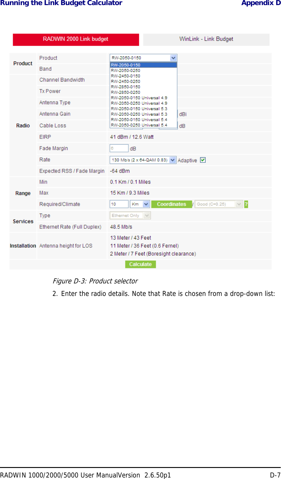
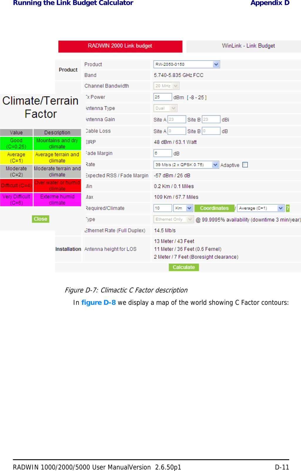
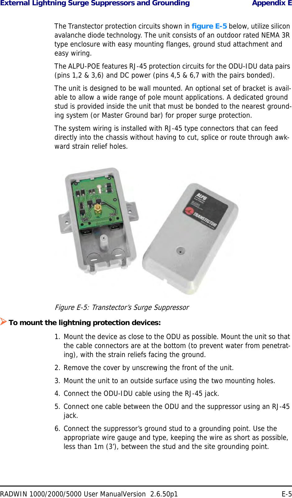
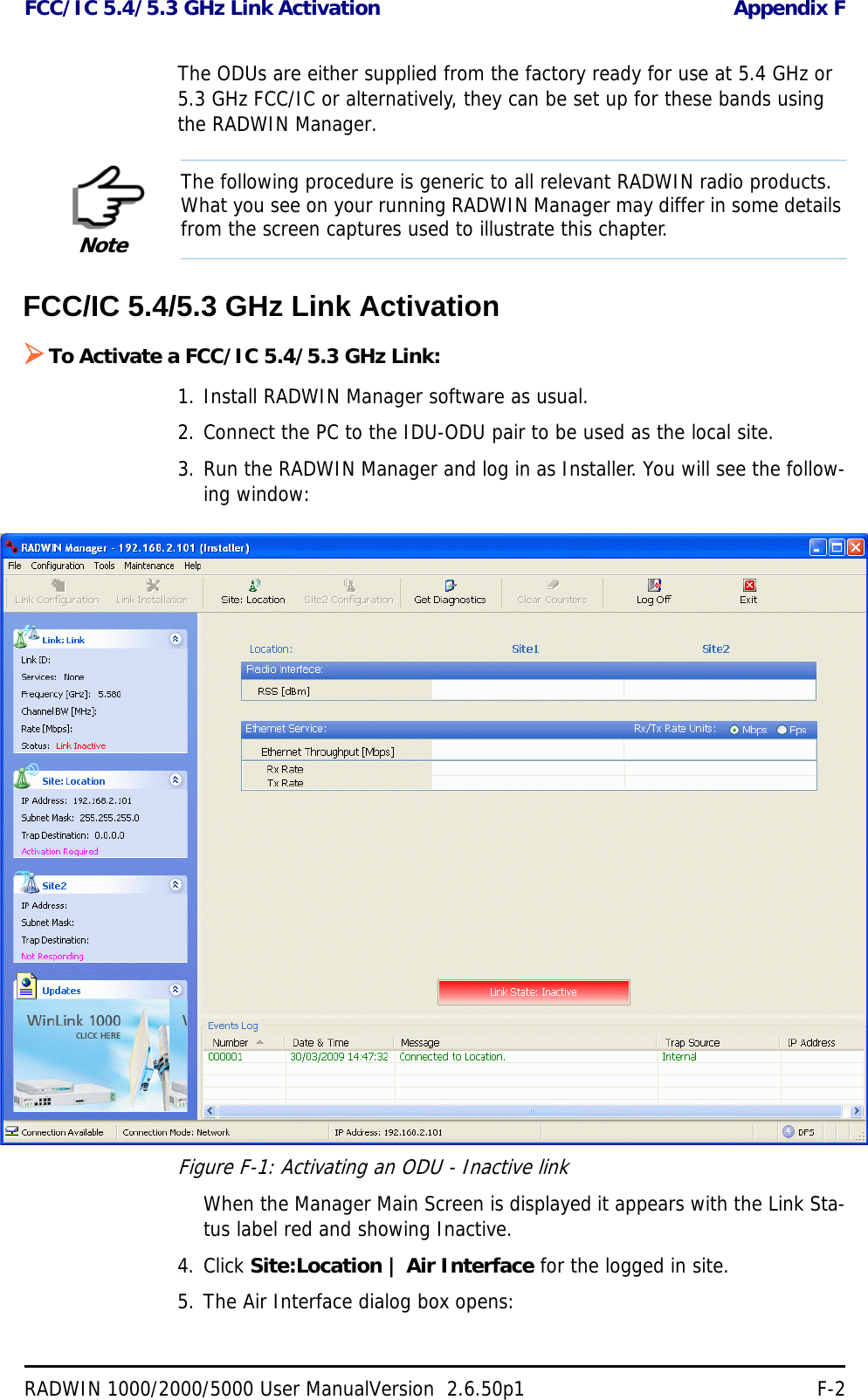
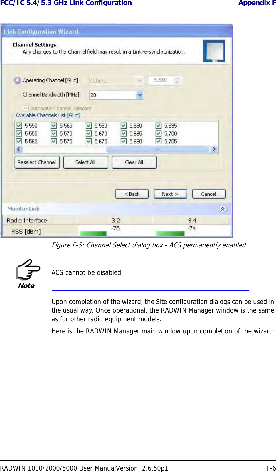
![Configuration with Telnet Chapter 6RADWIN 1000/2000/5000 User ManualVersion 2.6.50p1 6-20Configuration with TelnetA Telnet terminal can be used to configure and monitor the RADWIN 1000/2000/5000.To start a Telnet session, use telnet <manager IP>.For example, if you run Telnet as follows,telnet 10.0.0.120you will be asked for a user name and password.The login user name/password is identical to the Community strings; Read allows display only, Read/Write allows display and set commands.Supported Telnet commands are shown in table 6-2. Note that some of the commands are model-specific. For example, TDM commands will not apply to Ethernet only and PoE based links.Table 6-2: Telnet CommandsCommand Explanationdisplay inventory Displays ODU product name, Name, Location, hardware and software revisions, uptime, MAC address, IDU product name, IDU software and hardware revisionsdisplay management Displays IP, Subnet, Gateway, Traps tabledisplay link Displays State, Link ID, Channel BW, RSS, TSL, Frequency/ACS, DFS, Rate/ARA, Distancedisplay Ethernet Displays Bridge Mode, Aging time, Port table (State, Status and action)display tdm Displays Clock Mode, Master Clock Mode, Current Clock, Quality[1], TDM table (Line status, Error Blocks)display ntp Displays Time, Server and Offsetset ip <ipaddr> <subnetMask> <gateway> Set the ODU IP address, subnet mask and gatewayThe user must reset the ODU after the command completiondisplay PM <interface:AIR,LAN1,LAN2,TDM1,TDM2,TDM3,TDM4> <interval:current,day,month>Shows the performance monitor tables for each interface according to user defined monitoring intervalsset trap <index:1-10> <ipaddr> <port:0-65535> Set a specific trap from the traps table (set trap 3 10.0.0.133 162)set readpw <oldpasswd> <passwd> Set the read access password (Read Community)set writepw <oldpasswd> <passwd> Set the read-write access password (Read-Write Community)set trappw <oldpasswd> <passwd> Set the trap Community stringset buzzer <mode:0=OFF,1 =ON> Toggle the buzzer mode (0 – off, 1 – on)](https://usermanual.wiki/Radwin/RW2030.Revised-User-manual-part-2/User-Guide-1570439-Page-20.png)
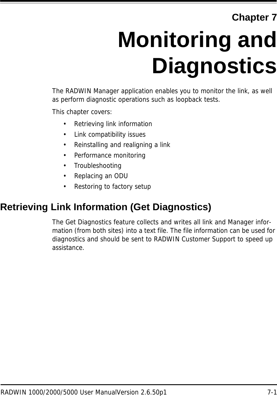
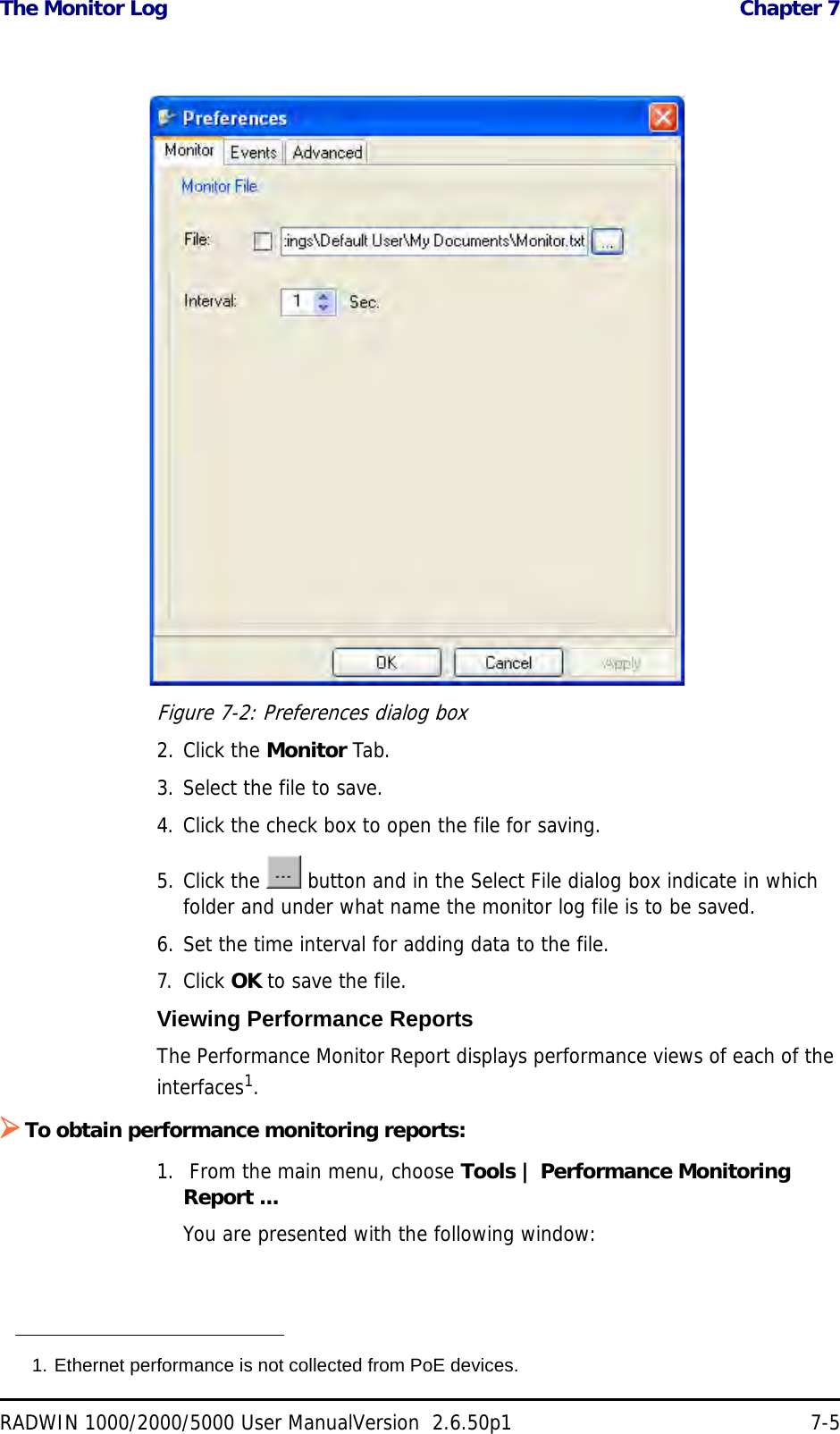
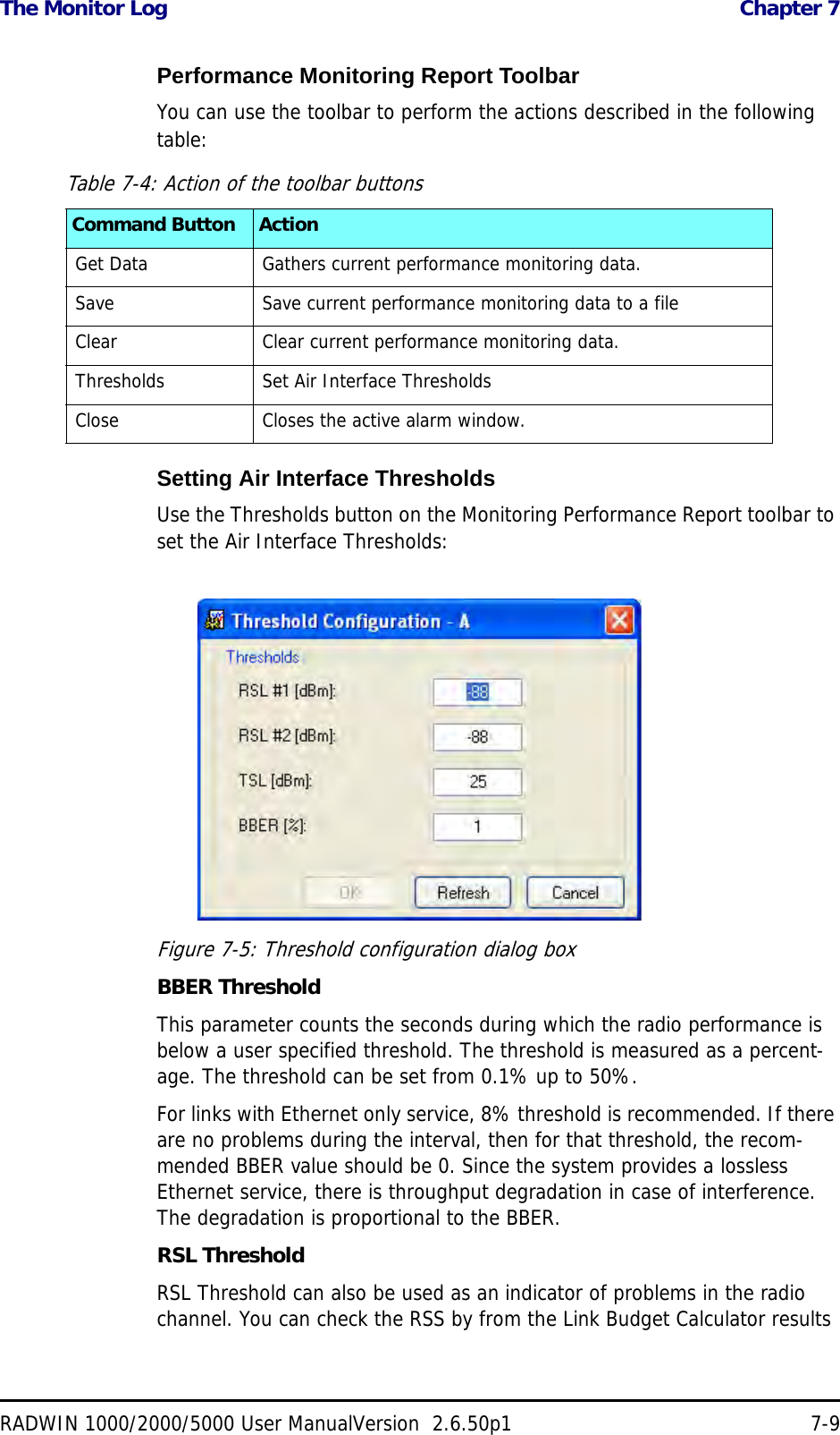
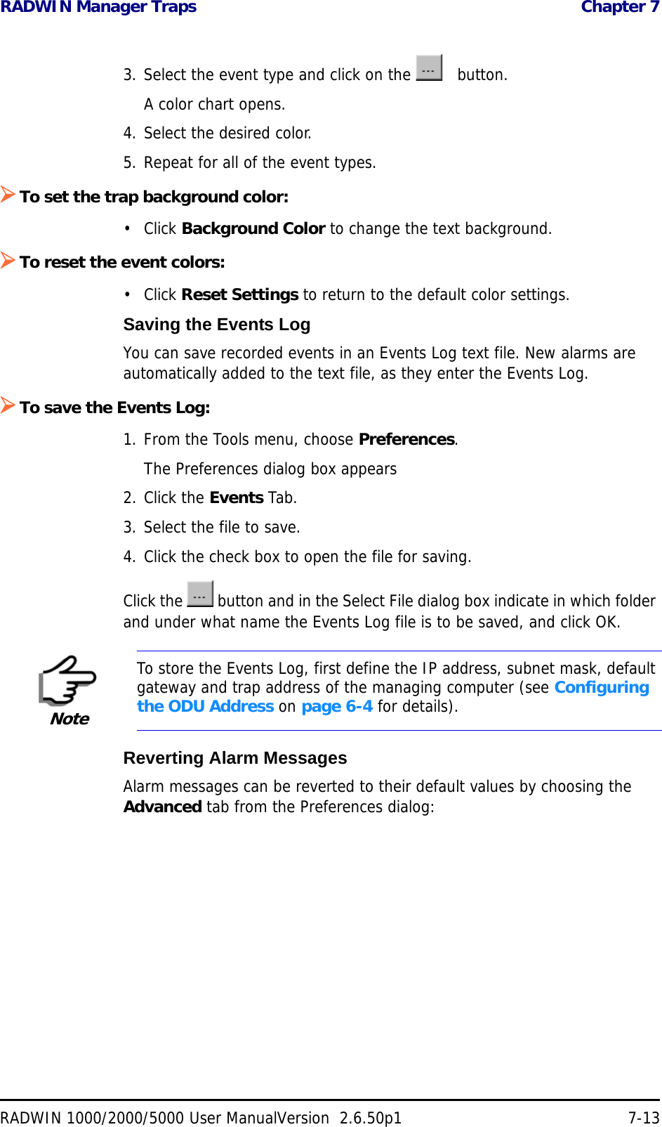
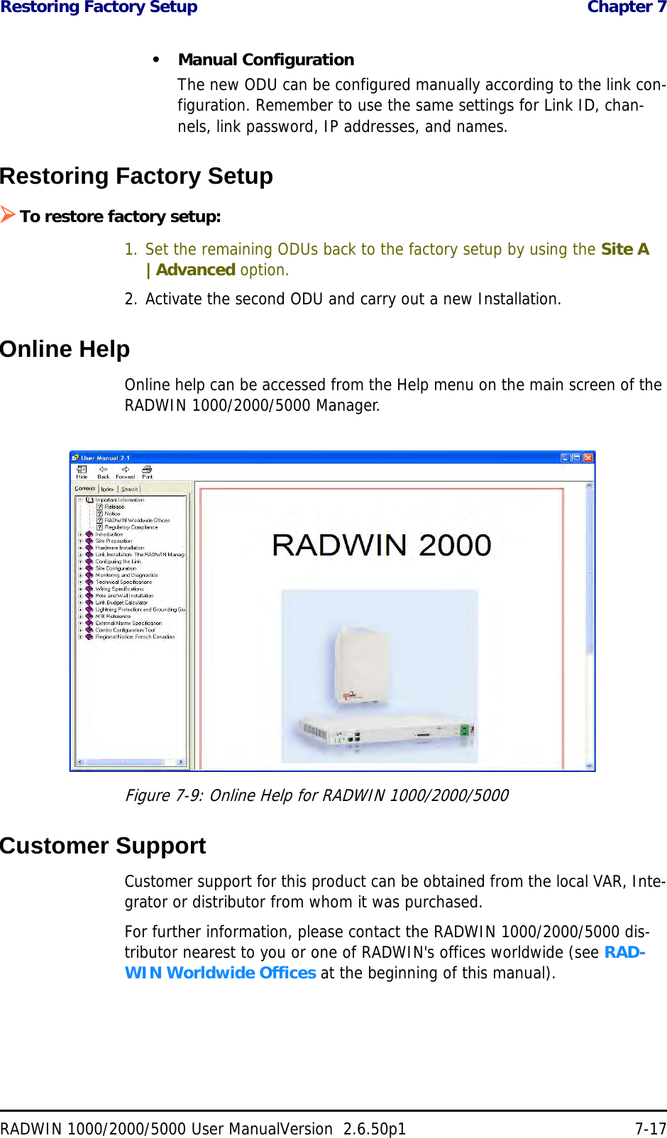
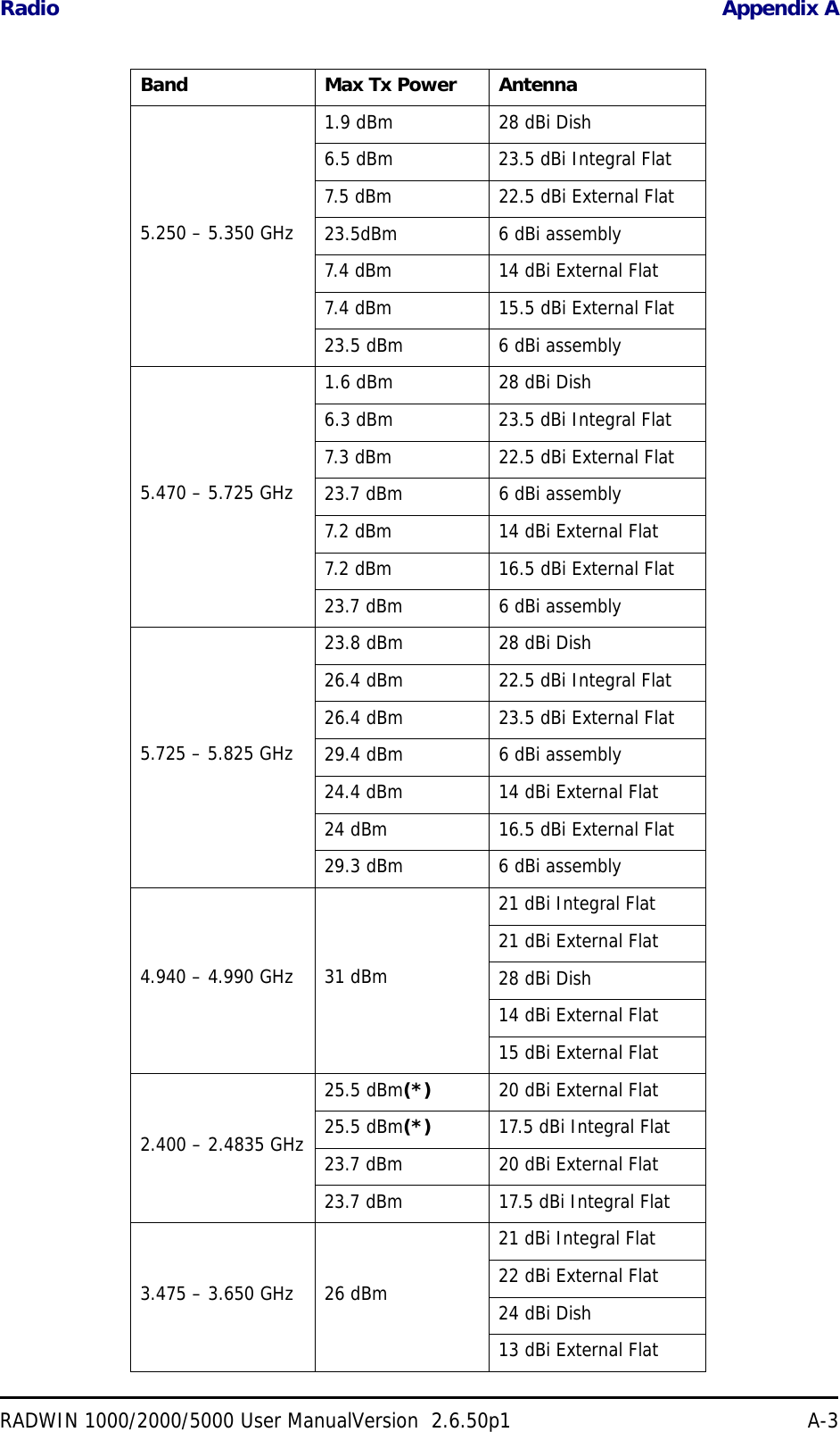
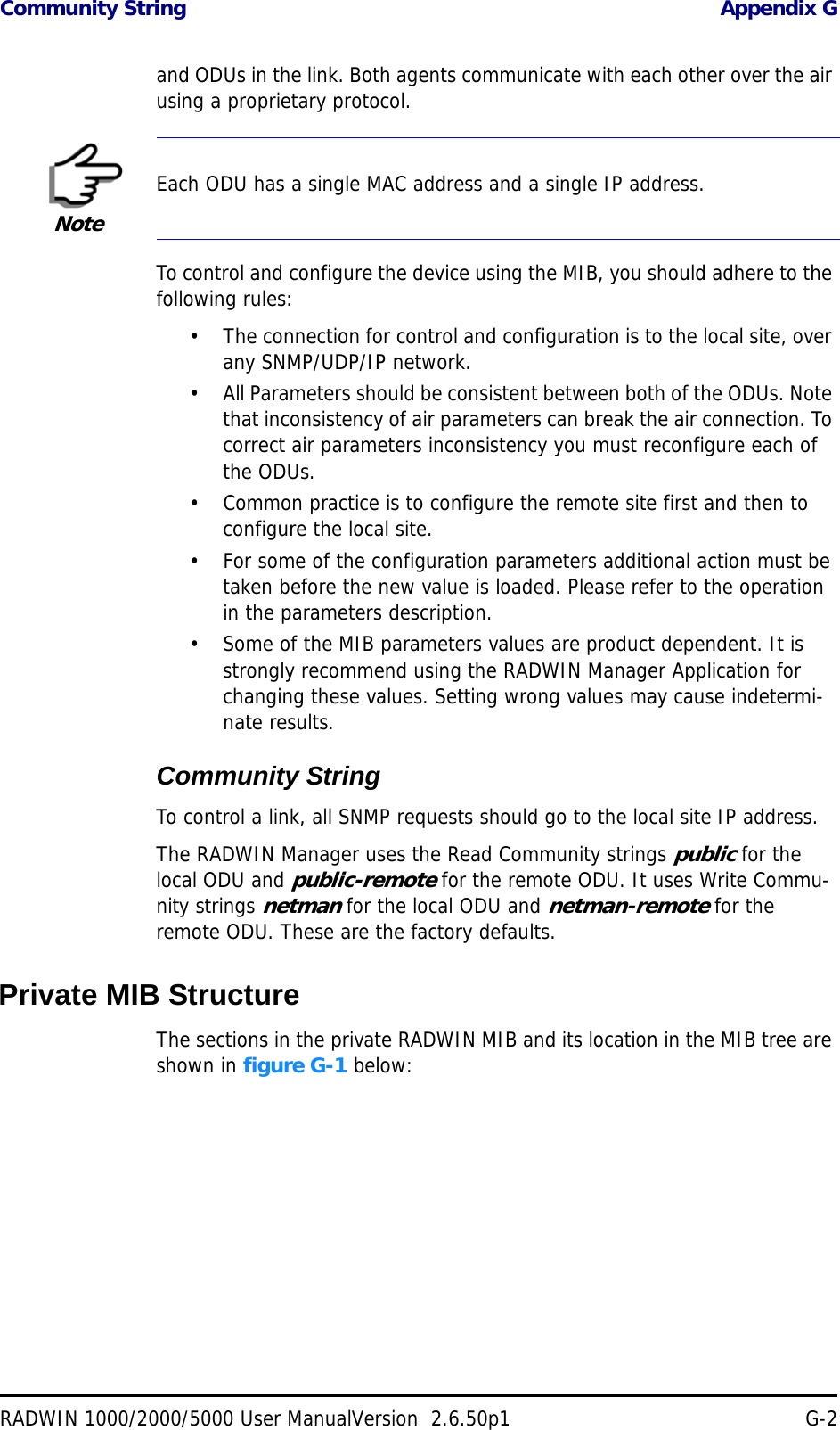
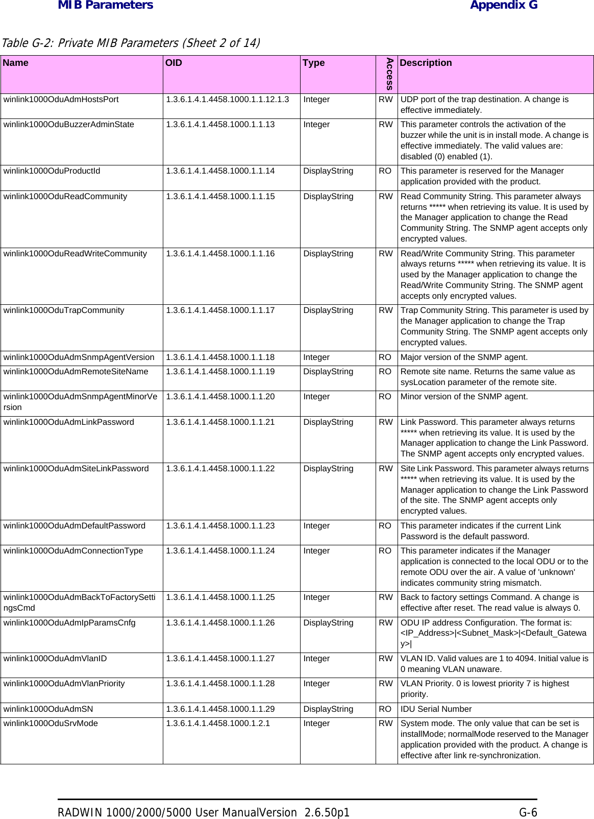
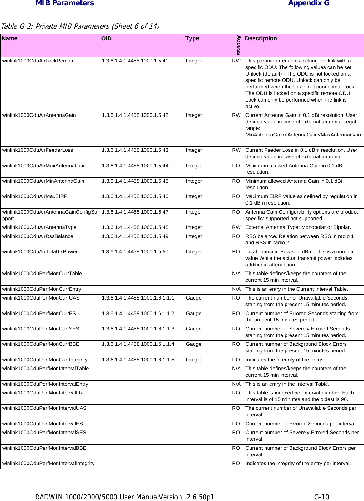
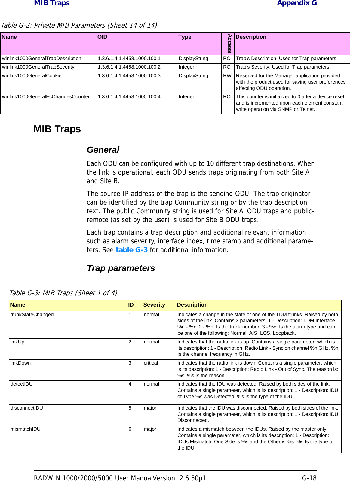
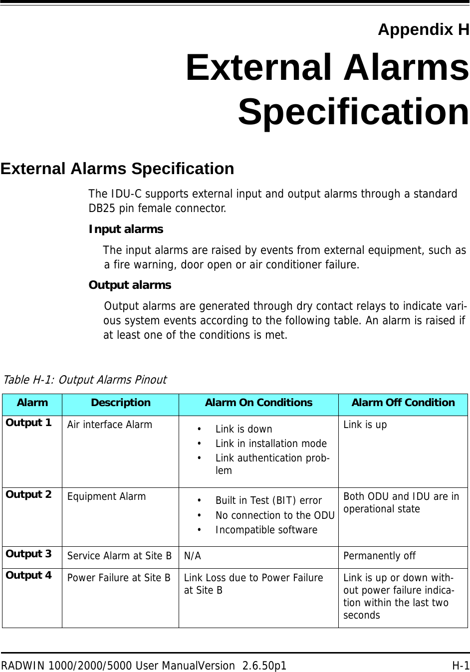
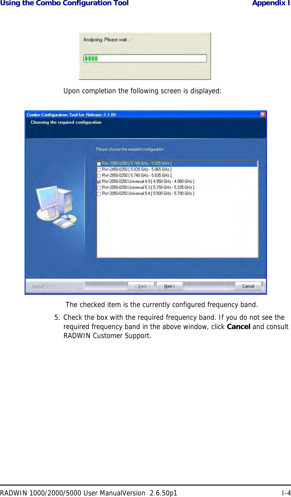
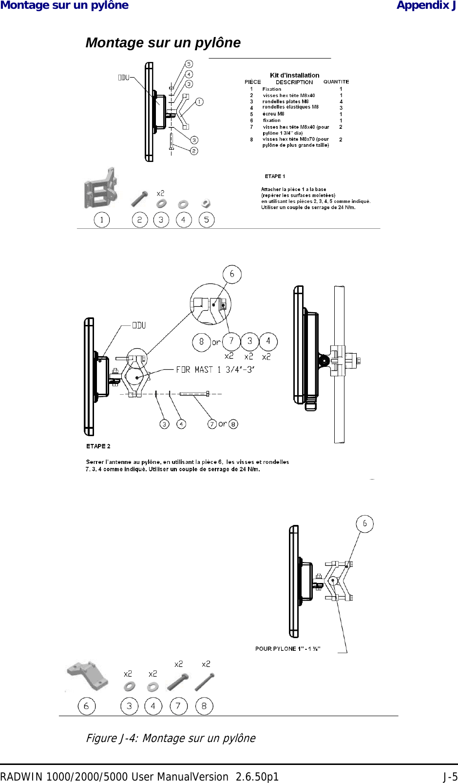
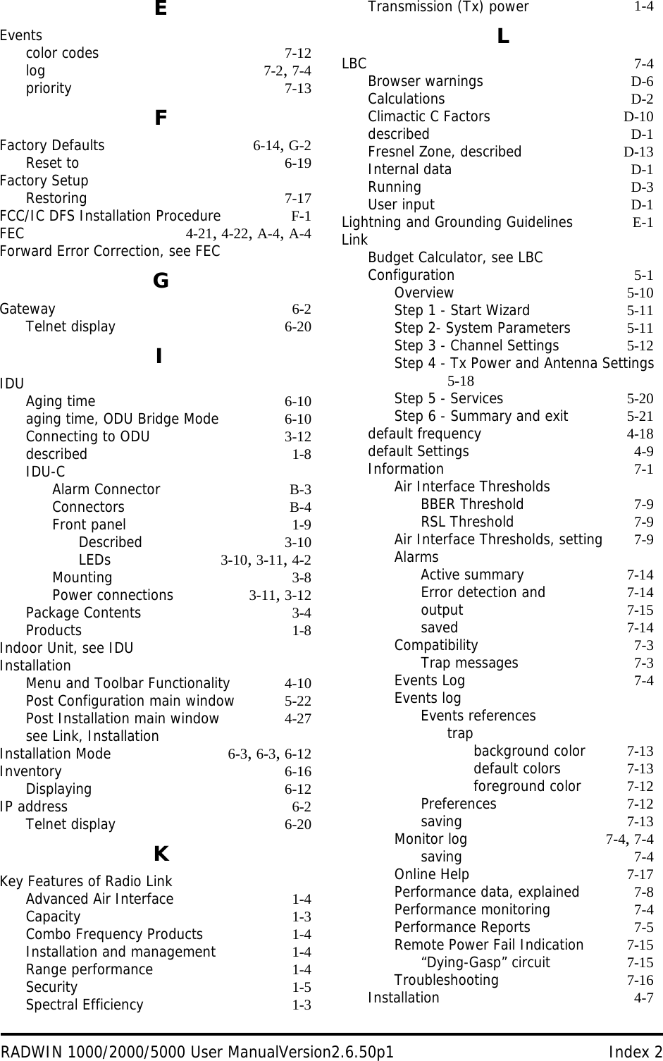
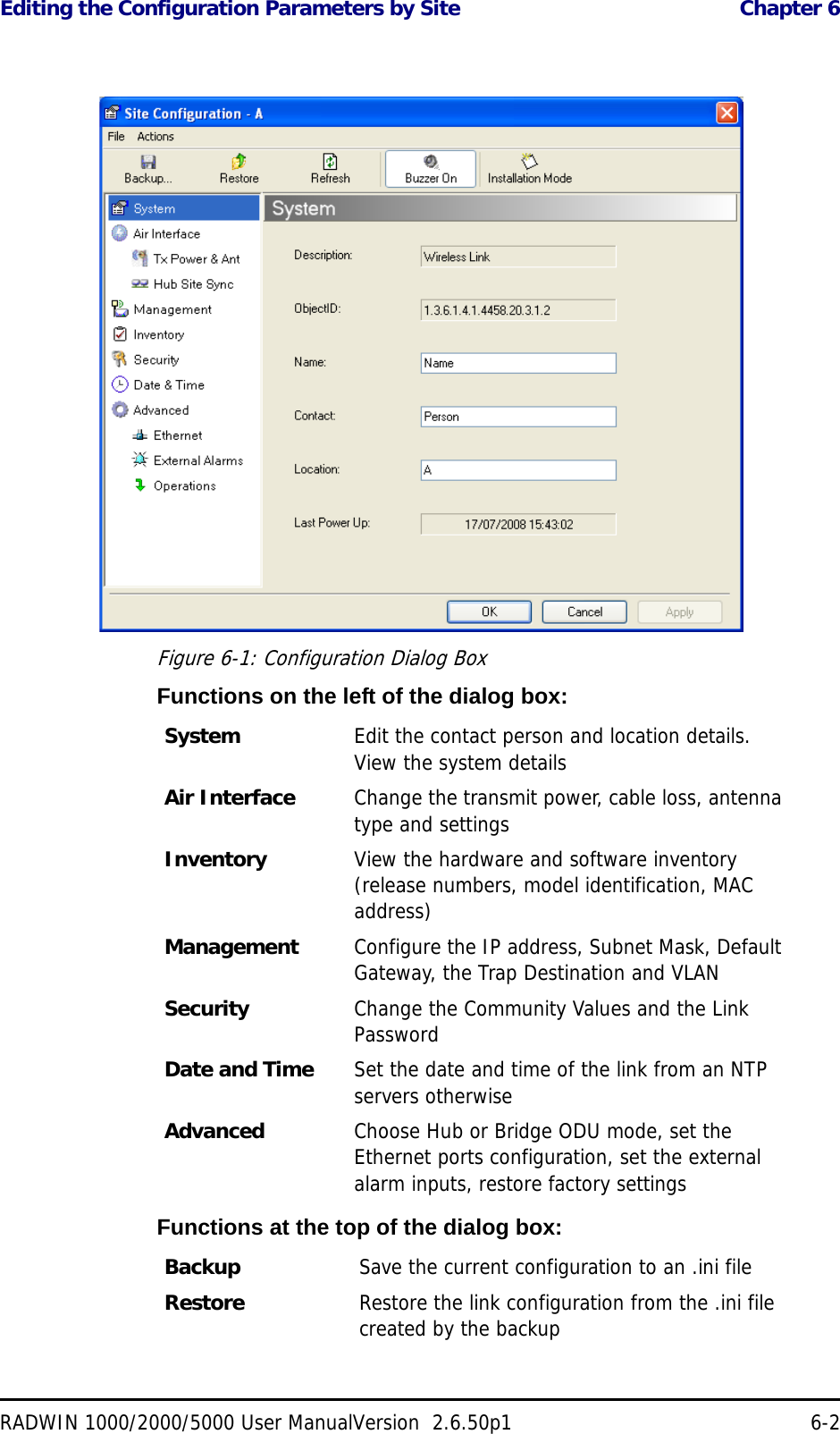
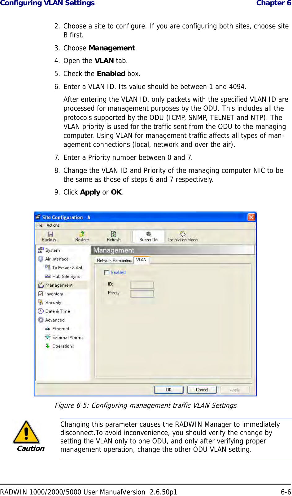
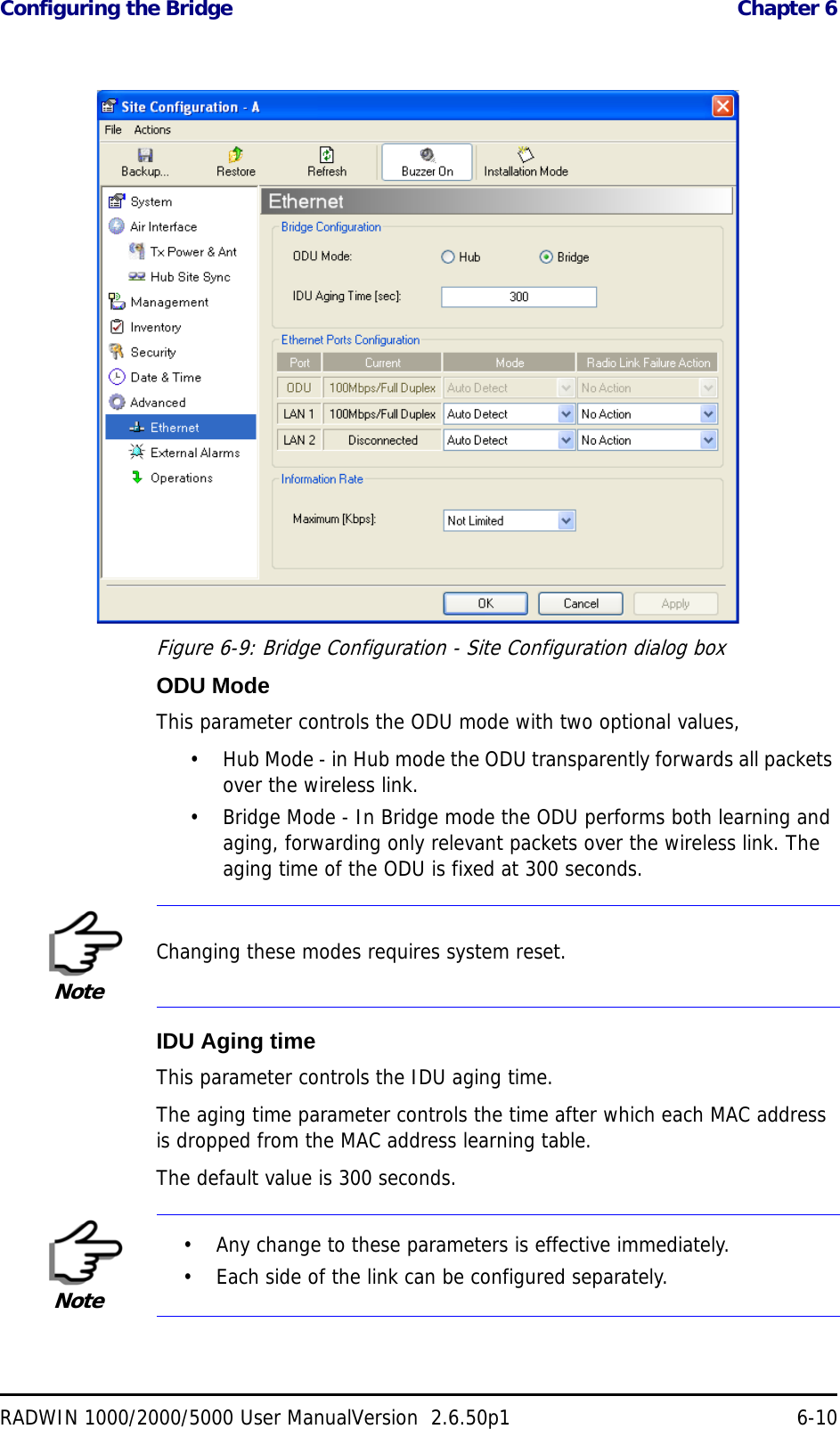
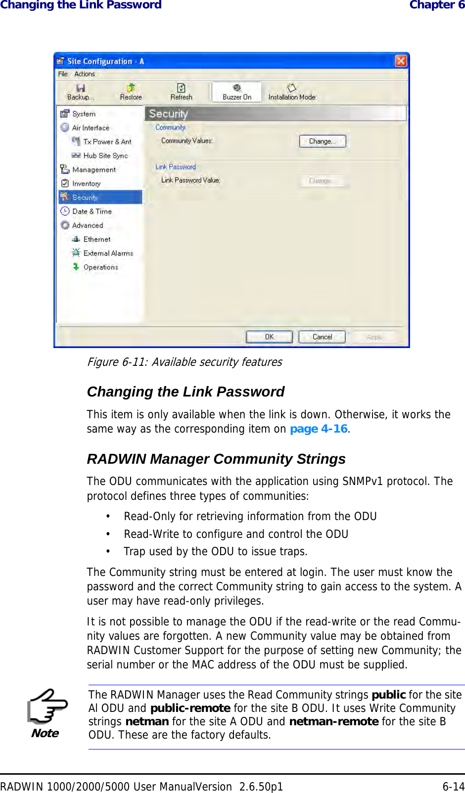
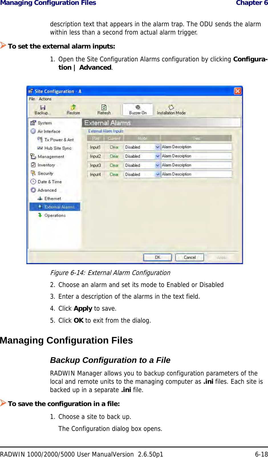
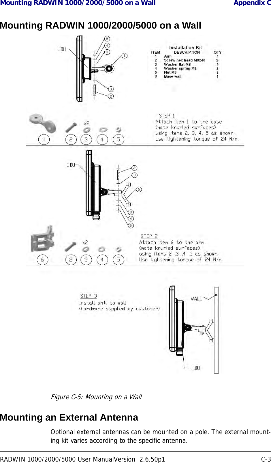
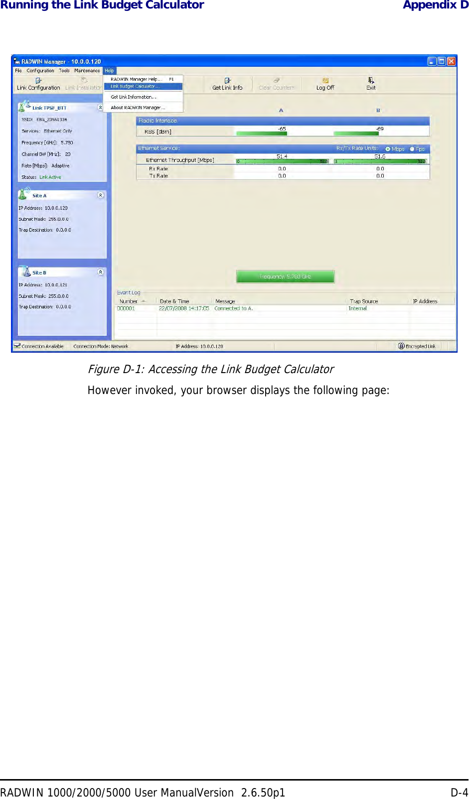
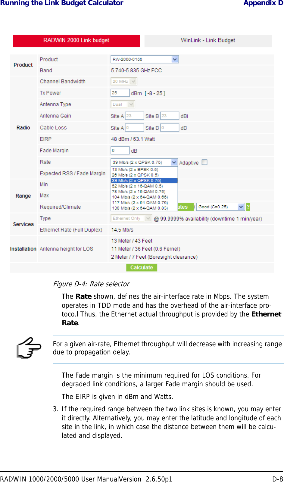
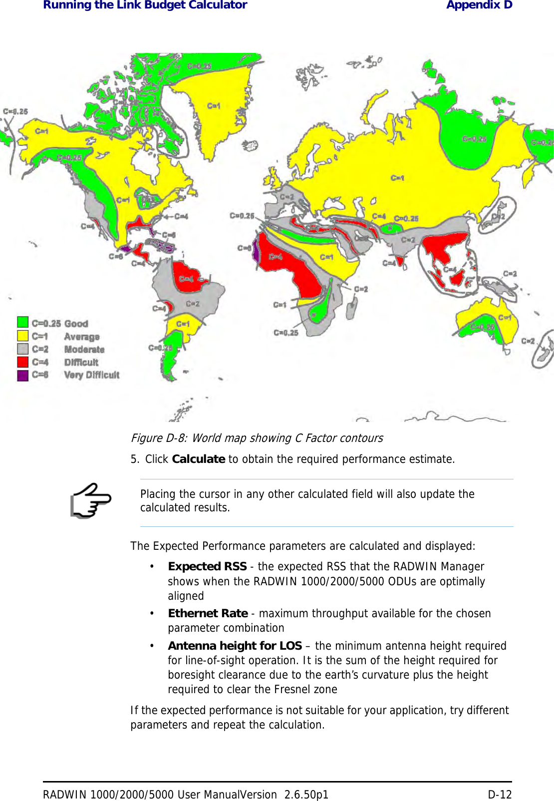
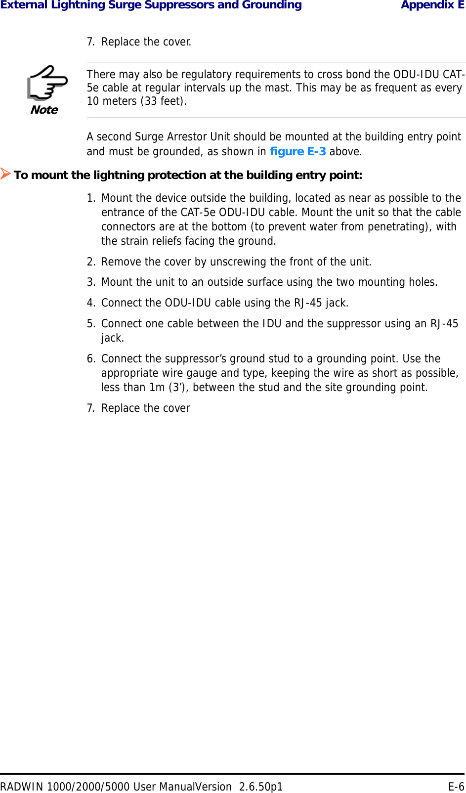
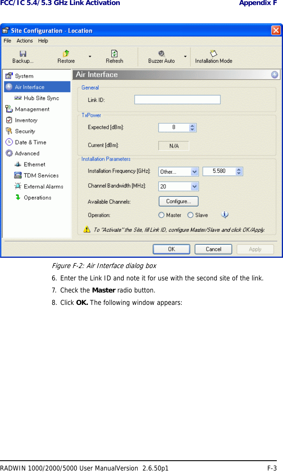
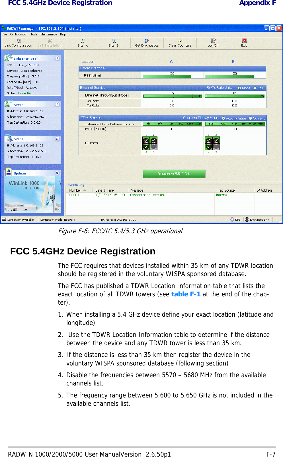
![Radio Appendix ARADWIN 1000/2000/5000 User ManualVersion 2.6.50p1 A-4(*) Relevant for RADWIN 1000 RW-1020-0150 / RADWIN 2000 RW-2020-0150 models only3.650 – 3.700 GHz26 dBm 13.5 dBi assembly13 dBi External Flat20 dBm 21 dBi Integral Flat22 dBi External Flat17 dBm 24 dBi Dish24 dBm 17 dBi assemblyChannel Bandwidth 5, 10, and 20 MHz, (10MHz not supported in the 5.8 GHz band)Radio Modulation 2x2 MIMO-OFDM (BPSK/QPSK/16QAM/64QAM)Adaptive Modulation & Coding SupportedAutomatic Channel Selection SupportedRadio Regulation FCC 47 CFR Part 15 Subpart C, E, Part 90 Subpart Y, ZIC (Canada) RSS-210, RSS-111, RSS-192, RSS-197Duplex Technology TDDError Correction FEC k = 1/2, 2/3, 3/4, 5/6Encryption AES 128Rate – Single Antenna [Mbps] 6.5 13 19.5 26 39 52 58.5 65Rate – Single Antenna in the 5.8 GHz spectrum band [Mbps] 13.5 27 40.5 54 81 108 121.5 135Rate – Dual Antenna [Mbps] 13 26 39 52 78 104 117 130Rate –Dual Antenna in the 5.8 GHz spectrum band [Mbps] 27 54 81 108 162 216 243 270Modulation BPSK QPSK 16QAM 64QAMFEC [k=] 1/2 1/2 3/4 1/2 3/4 2/3 3/4 5/6Max Tx Power [dBm] 25 24 21 19 18Sensitivity (dBm) @BER <10e-11 (20MHz) -88 -86 -83 -81 -80 -72 -70 -67Band Max Tx Power Antenna](https://usermanual.wiki/Radwin/RW2030.Revised-User-manual-part-2/User-Guide-1570439-Page-43.png)
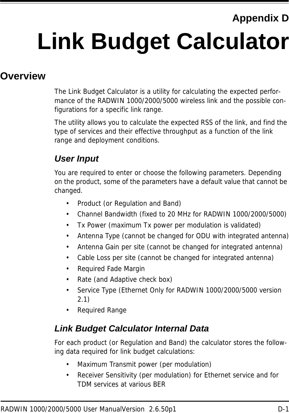
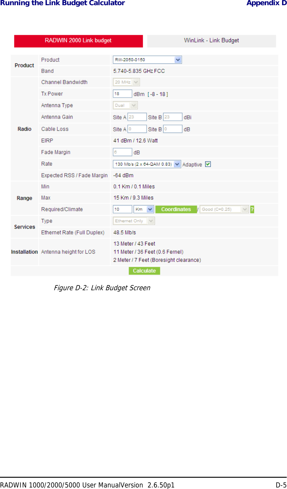
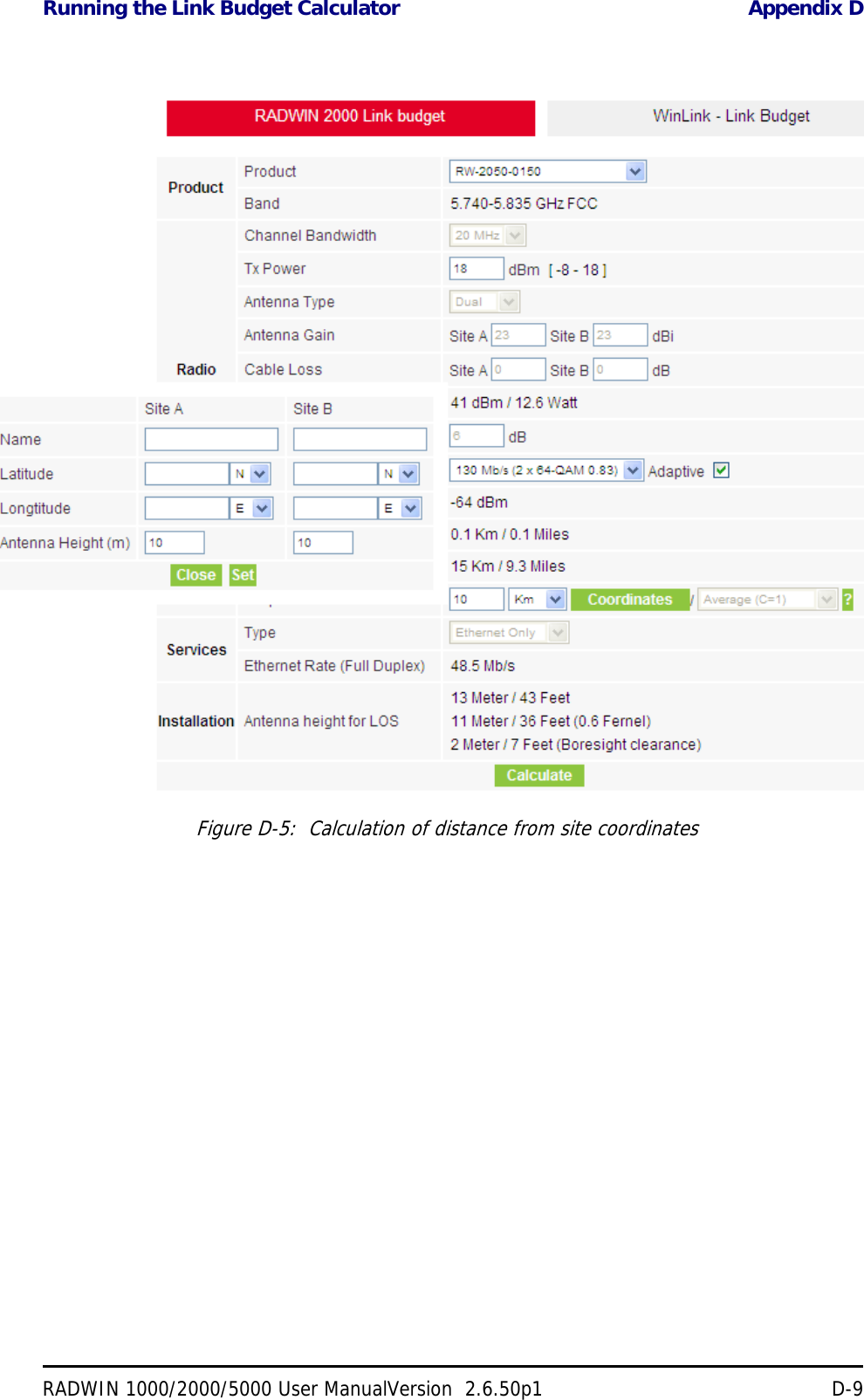
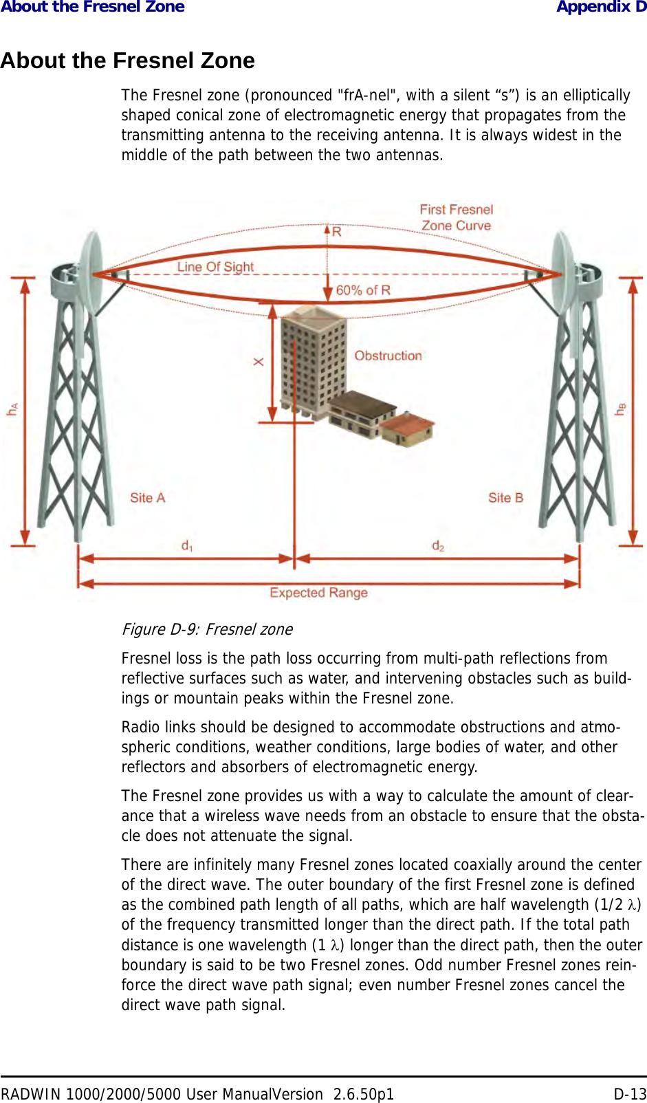
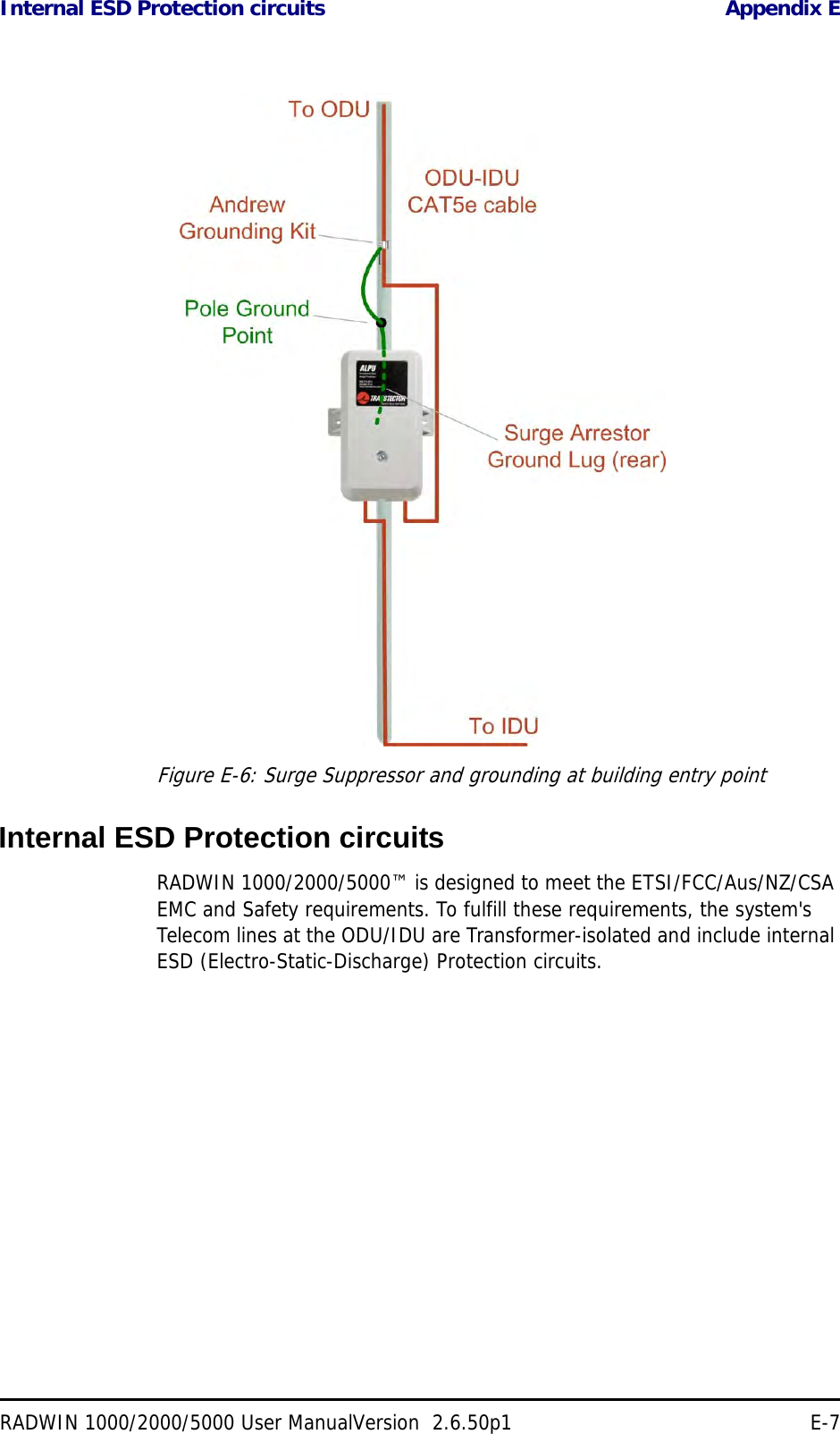
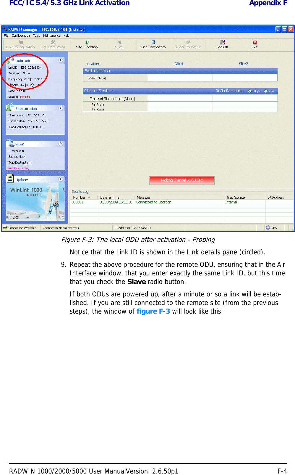
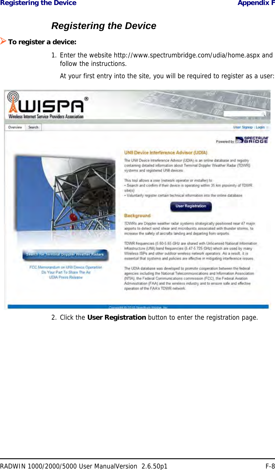
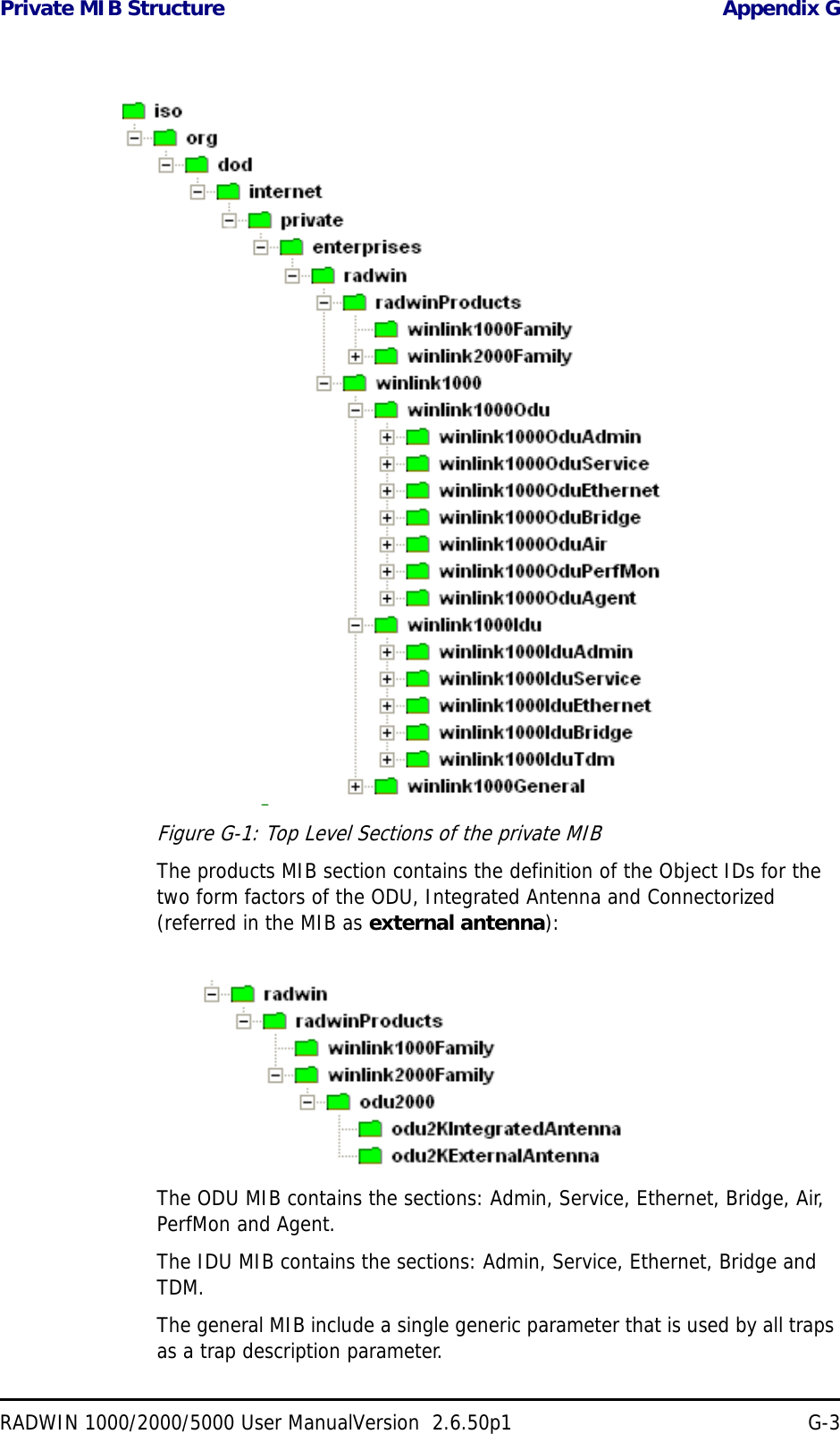
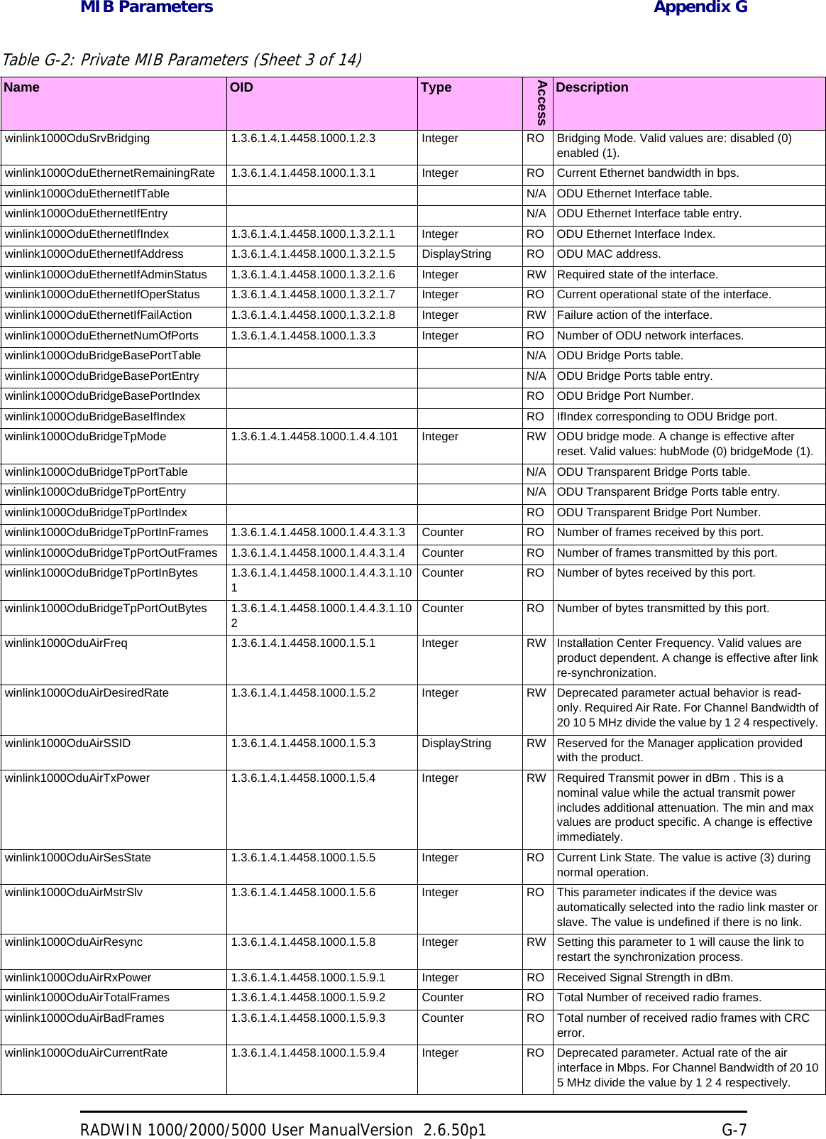
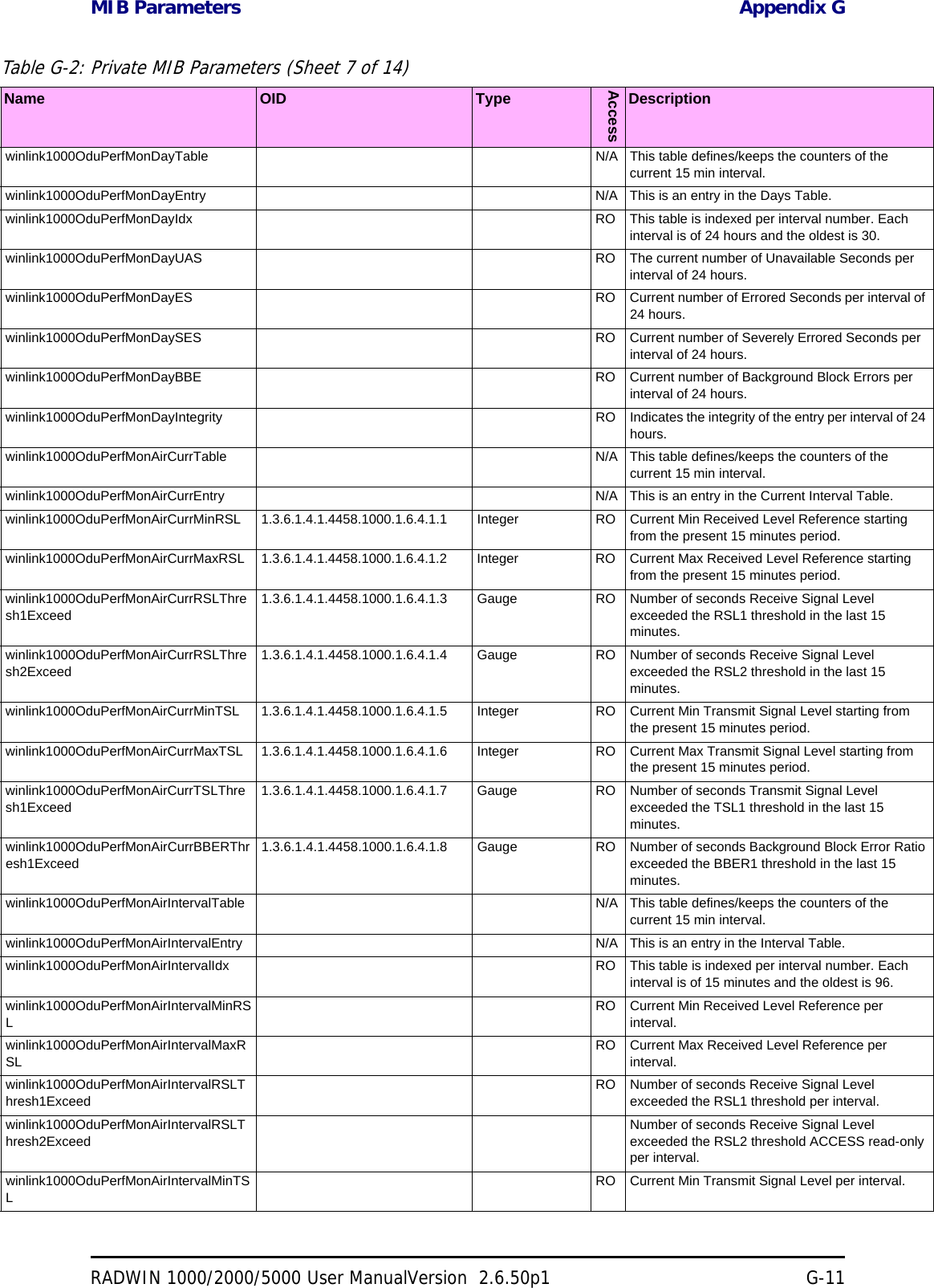
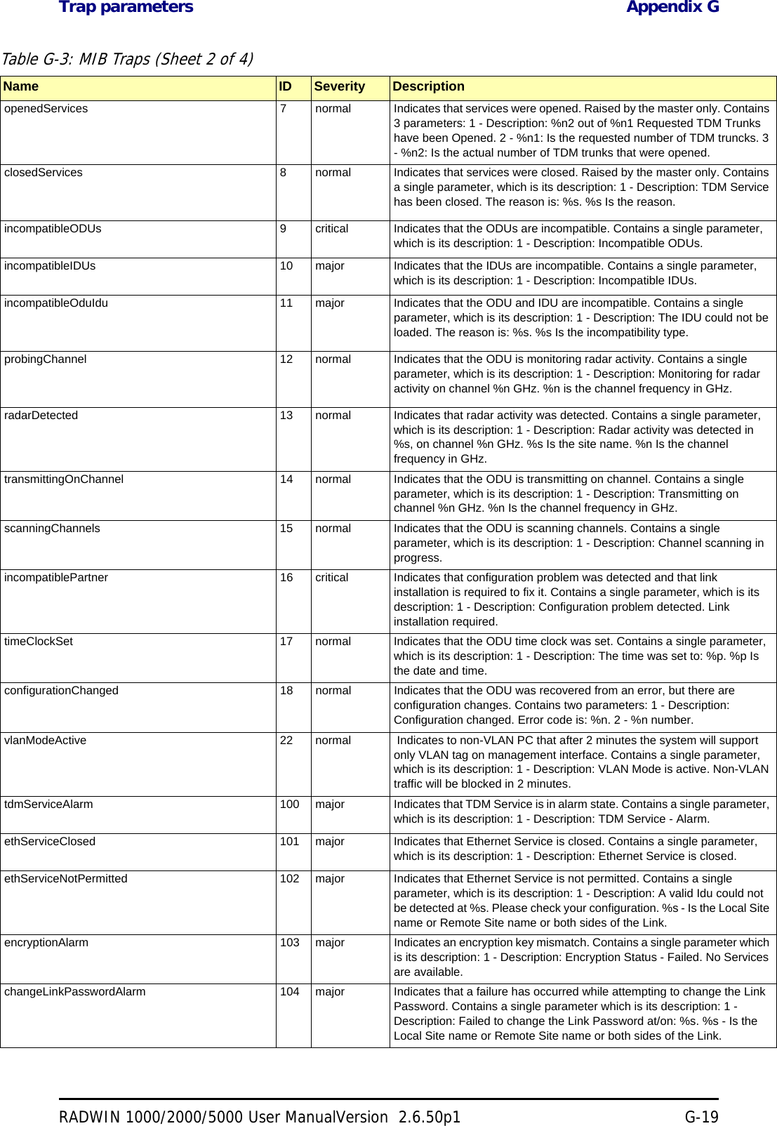
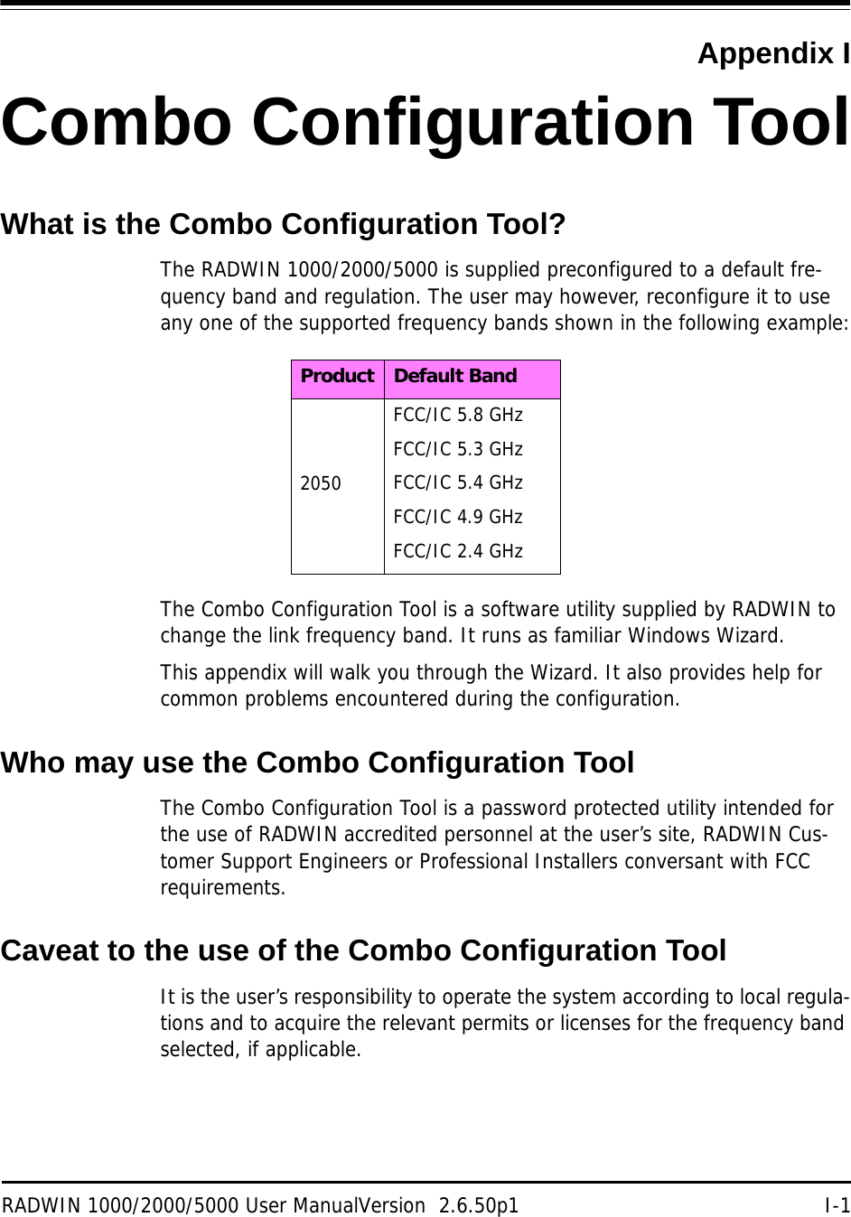
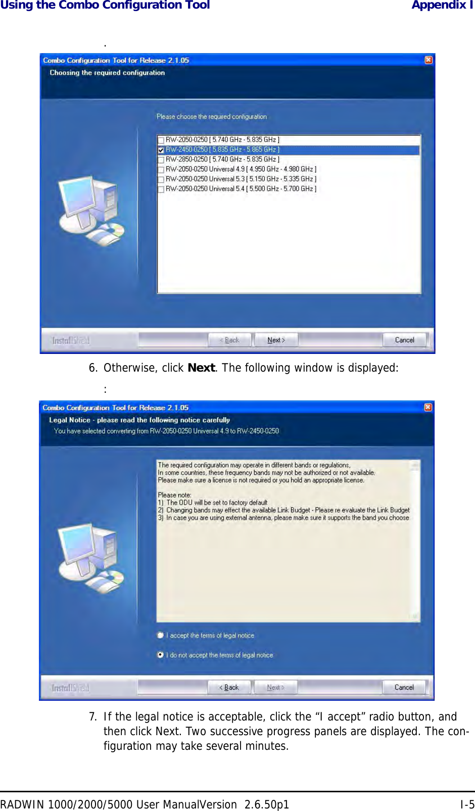
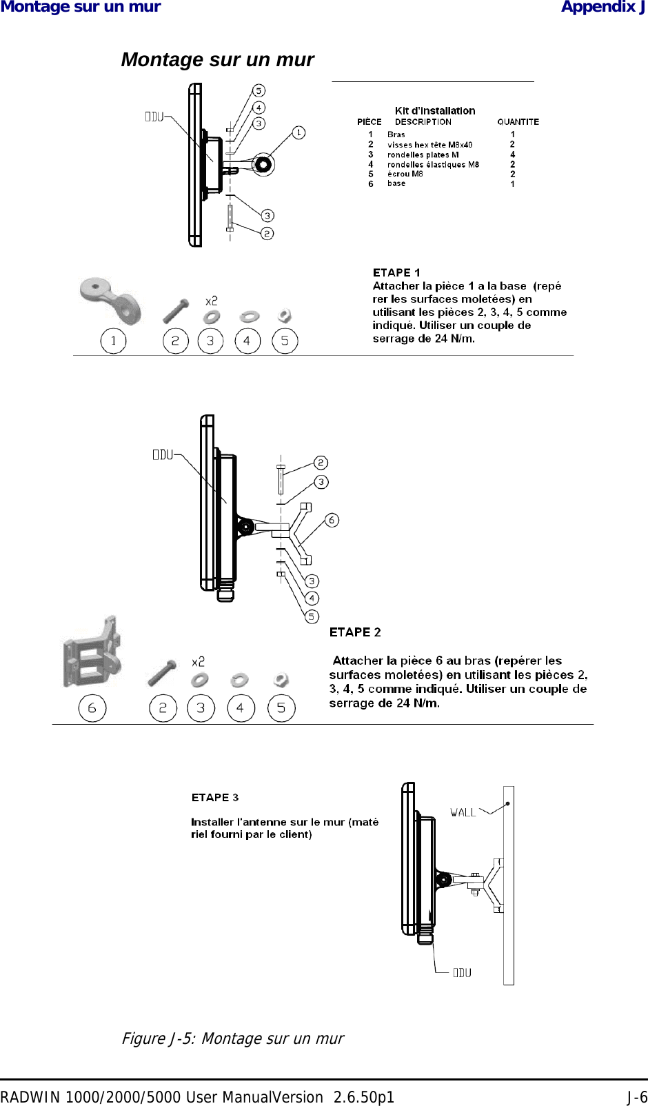
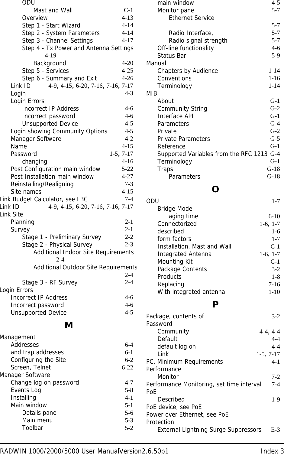
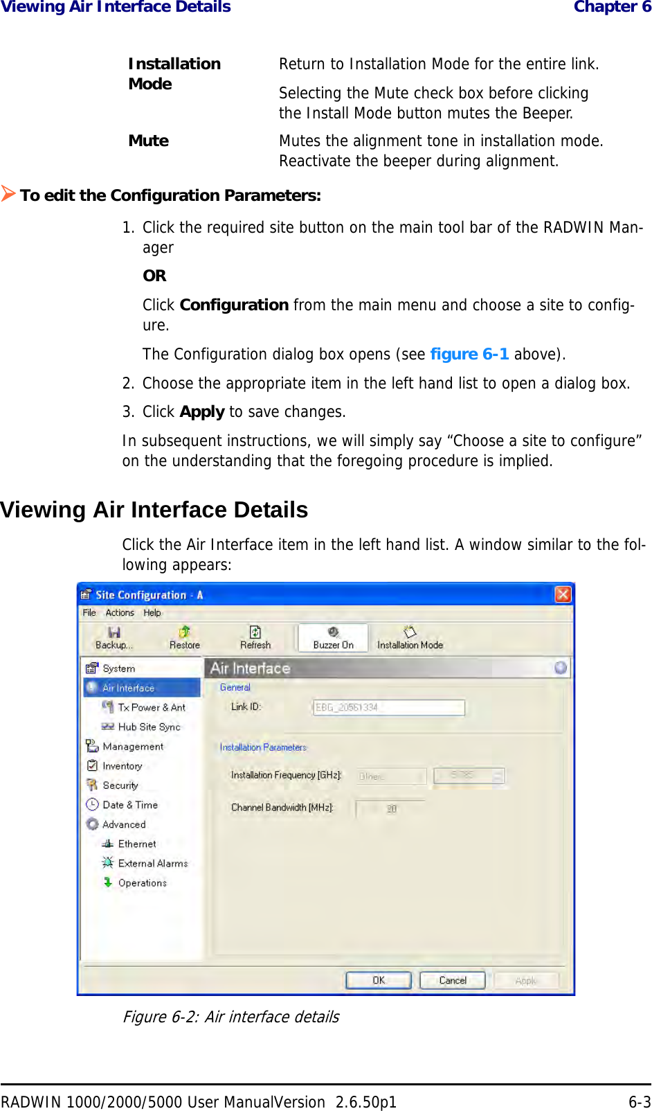
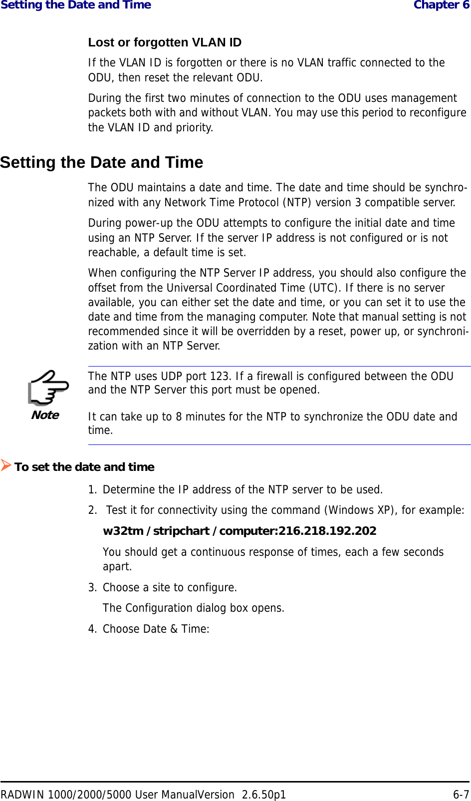
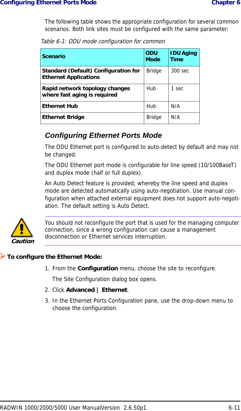
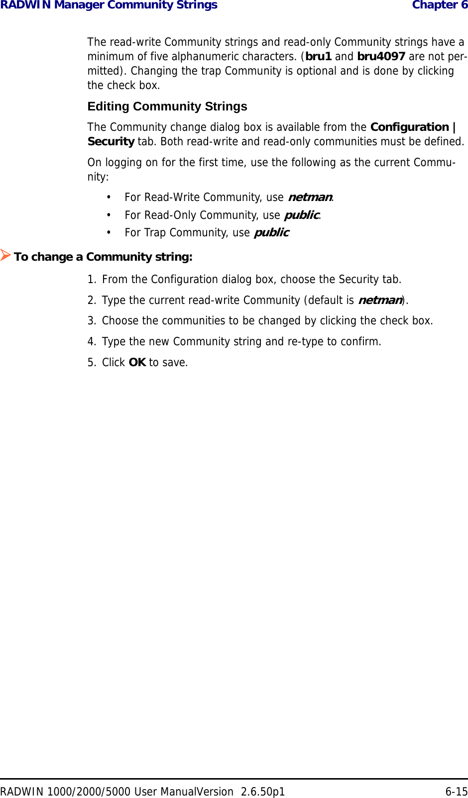
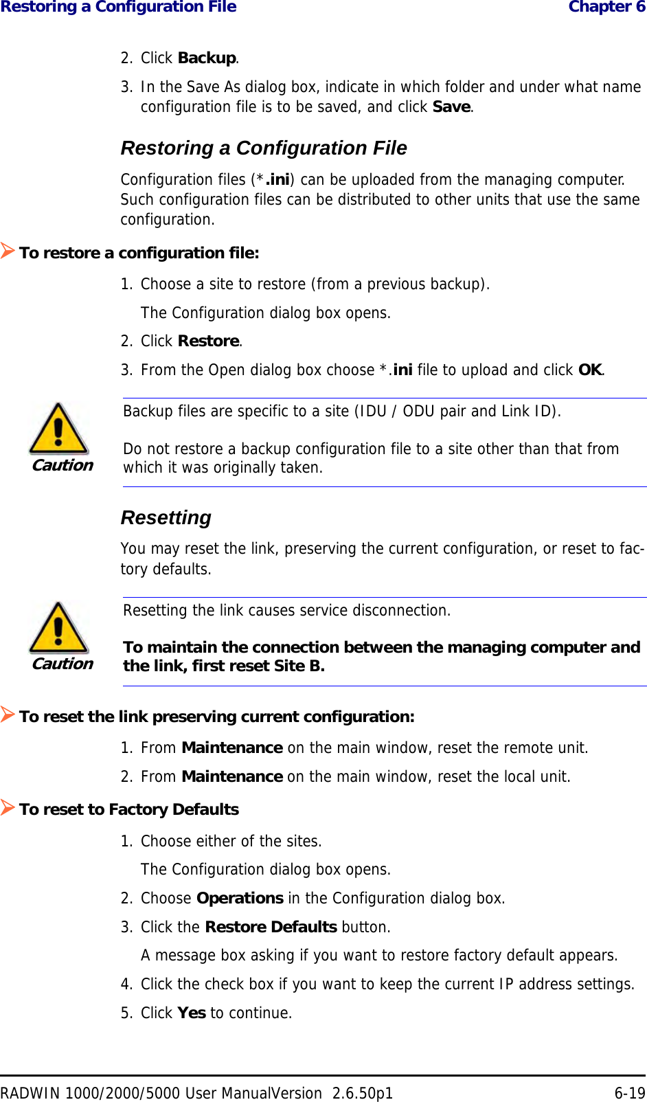
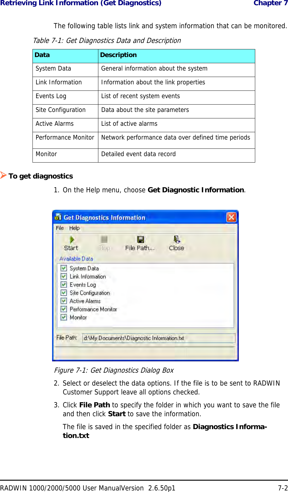
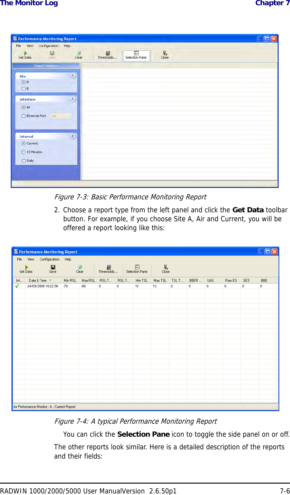
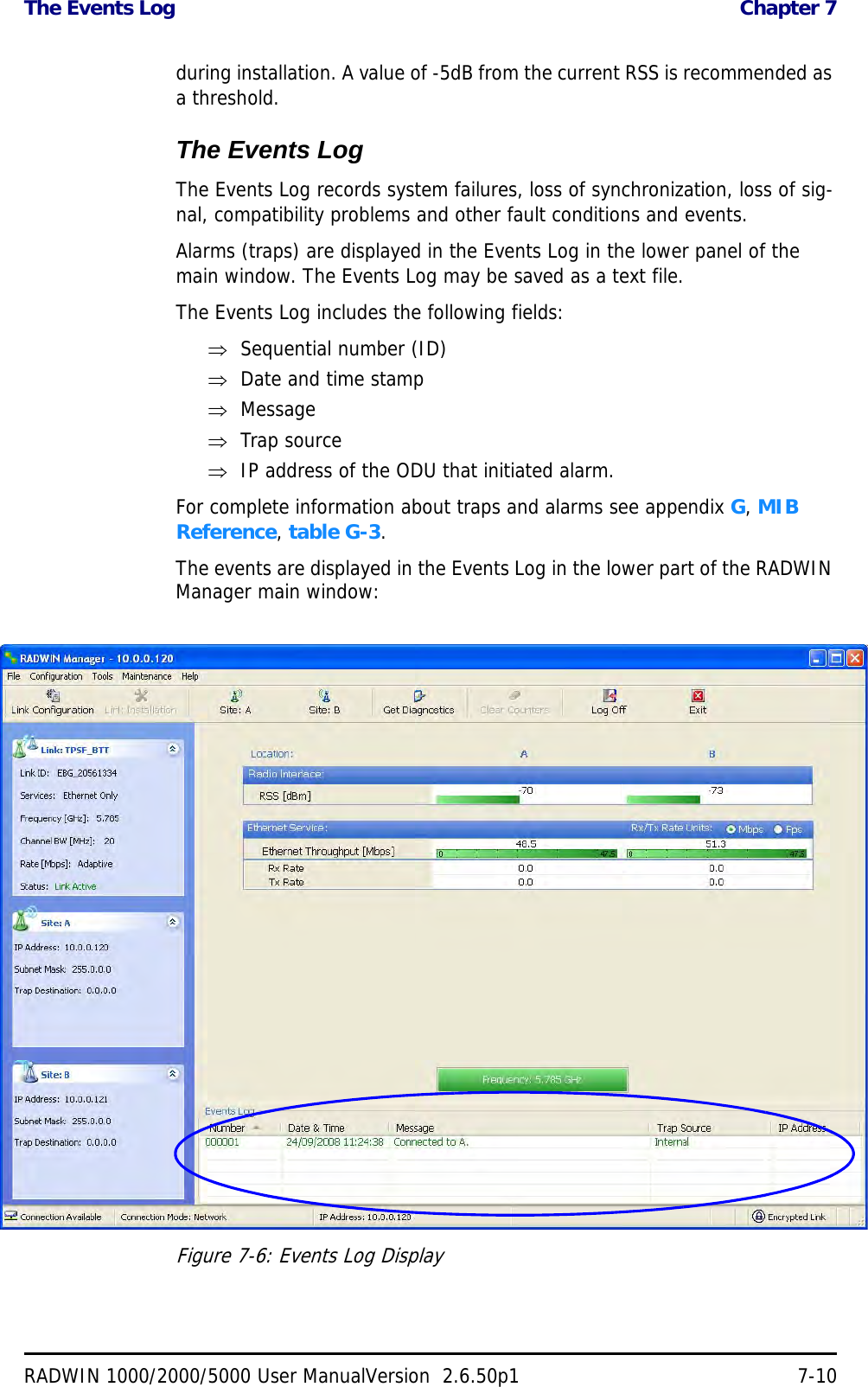
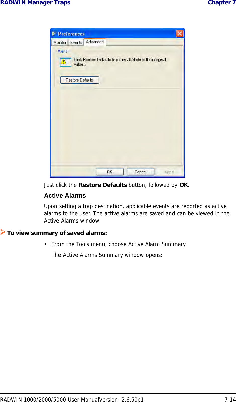
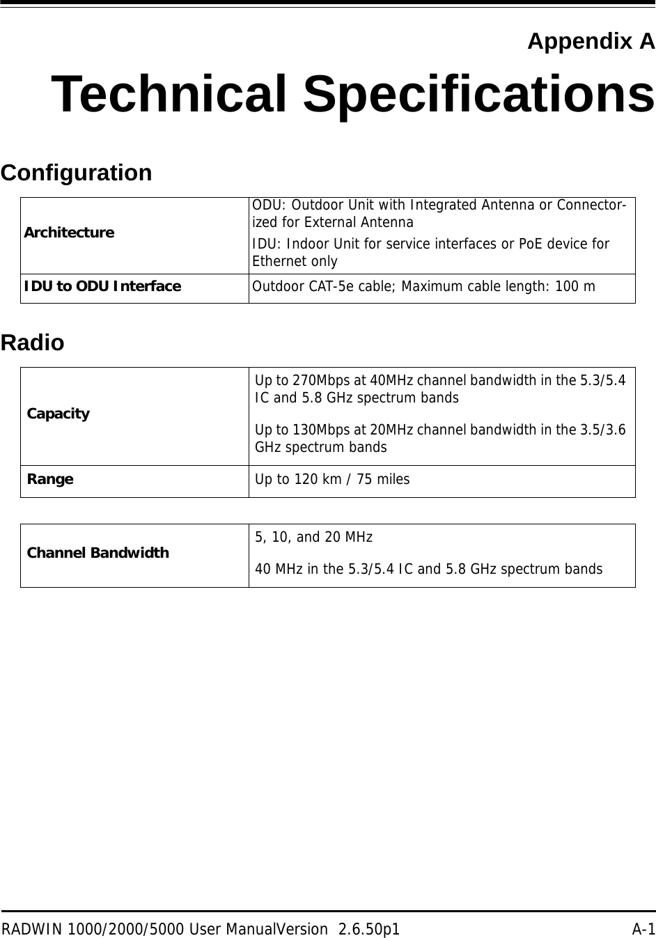
![TDWR Table Appendix FRADWIN 1000/2000/5000 User ManualVersion 2.6.50p1 F-11TDWR TableThe following table contains the latitude and longitude locations of Terminal Doppler Weather Radars (TDWR). Use this table to determine if the Master or Client device installed is within 35 km radius of a TDWR location. If one of the installed devices is within 35 km radius of any TDWR location then disable all frequencies between 5570 – 5680 MHz from the available chan-nels list.Table F-1: Latitude and longitude locations of TDWRsSTATE CITY LONGITUDE LATITUDE FREQUENCY TERRAIN ELEVATION (MSL) [ft] ANTENNA HEIGHT ABOVE TERRAIN [ft] AZ PHOENIX W 112 09 46 N 33 25 14 5610 MHz 1024 64 CO DENVER W 104 31 35 N 39 43 39 5615 MHz 5643 64 FL FT LAUDERDALE W 080 20 39 N 26 08 36 5645 MHz 7 113 FL MIAMI W 080 29 28 N 25 45 27 5605 MHz 10 113 FL ORLANDO W 081 19 33 N 28 20 37 5640 MHz 72 97 FL TAMPA W 082 31 04 N 27 51 35 5620 MHz 14 80 FL WEST PALM BEACH W 080 16 23 N 26 41 17 5615 MHz 20 113 GA ATLANTA W 084 15 44 N 33 38 48 5615 MHz 962 113 IL MCCOOK W 087 51 31 N 41 47 50 5615 MHz 646 97 IL CRESTWOOD W 087 43 47 N 41 39 05 5645 MHz 663 113 IN INDIANAPOLIS W 086 26 08 N 39 38 14 5605 MHz 751 97 KS WICHITA W 097 26 13 N 37 30 26 5603 MHz 1270 80 KY COVINGTON CINCINNATI W 084 34 48 N 38 53 53 5610 MHz 942 97 KY LOUISVILLE W 085 36 38 N 38 02 45 5646 MHz 617 113 LA NEW ORLEANS W 090 24 11 N 30 01 18 5645 MHz 2 97 MA BOSTON W 070 56 01 N 42 09 30 5610 MHz 151 113 MD BRANDYWINE W 076 50 42 N 38 41 43 5635 MHz 233 113 MD BENFIELD W 076 37 48 N 39 05 23 5645 MHz 184 113 MD CLINTON W 076 57 43 N 38 45 32 5615 MHz 249 97 MI DETROIT W 083 30 54 N 42 06 40 5615 MHz 656 113 MN MINNEAPOLIS W 092 55 58 N 44 52 17 5610 MHz 1040 80 MO KANSAS CITY W 094 44 31 N 39 29 55 5605 MHz 1040 64 MO SAINT LOUIS W 090 29 21 N 38 48 20 5610 MHz 551 97 MS DESOTO COUNTY W 089 59 33 N 34 53 45 5610 MHz 371 113 NC CHARLOTTE W 080 53 06 N 35 20 14 5608 MHz 757 113 NC RALEIGH DURHAM W 078 41 50 N 36 00 07 5647 MHz 400 113 NJ WOODBRIDGE W 074 16 13 N 40 35 37 5620 MHz 19 113 NJ PENNSAUKEN W 075 04 12 N 39 56 57 5610 MHz 39 113](https://usermanual.wiki/Radwin/RW2030.Revised-User-manual-part-2/User-Guide-1570439-Page-84.png)
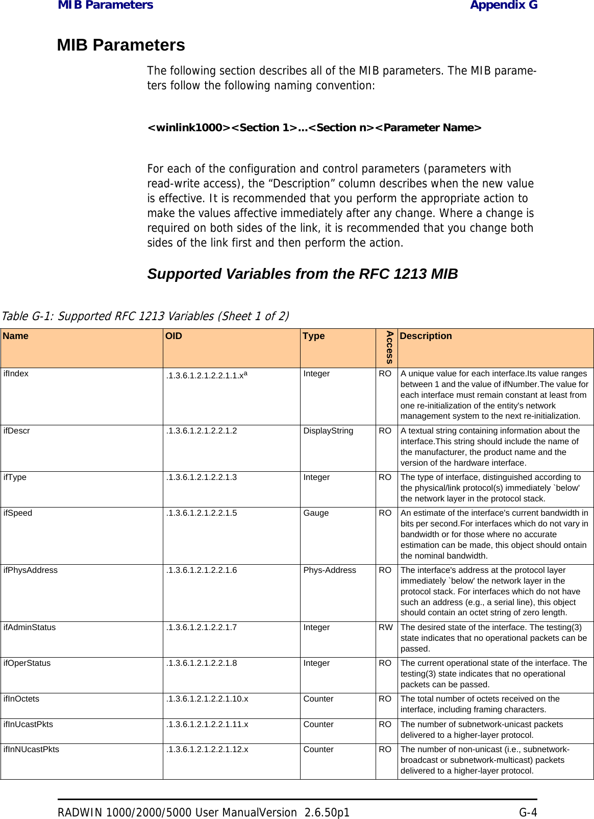
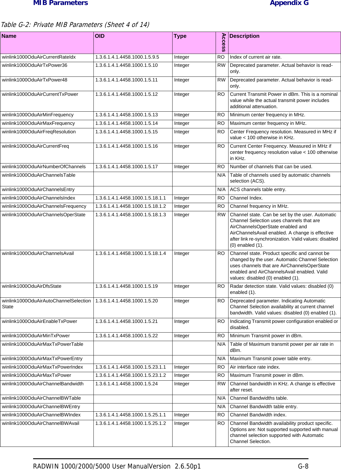
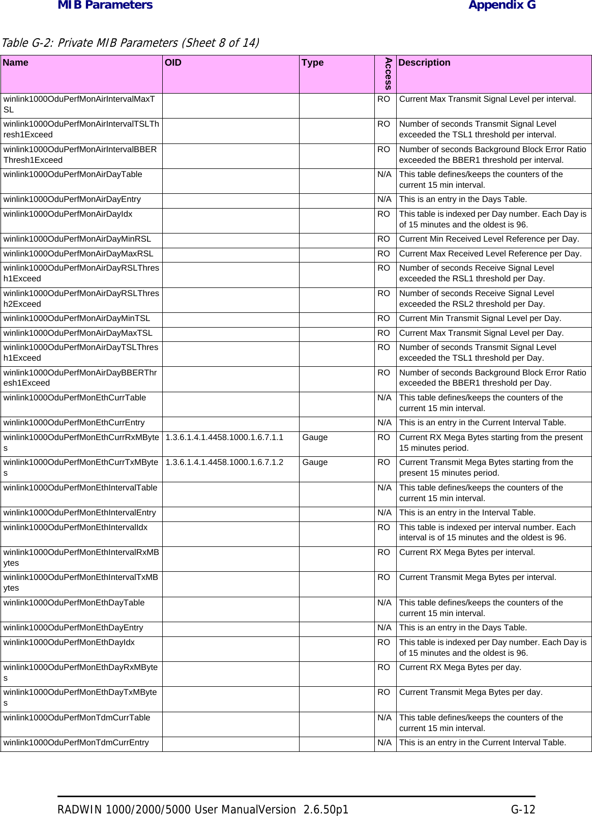
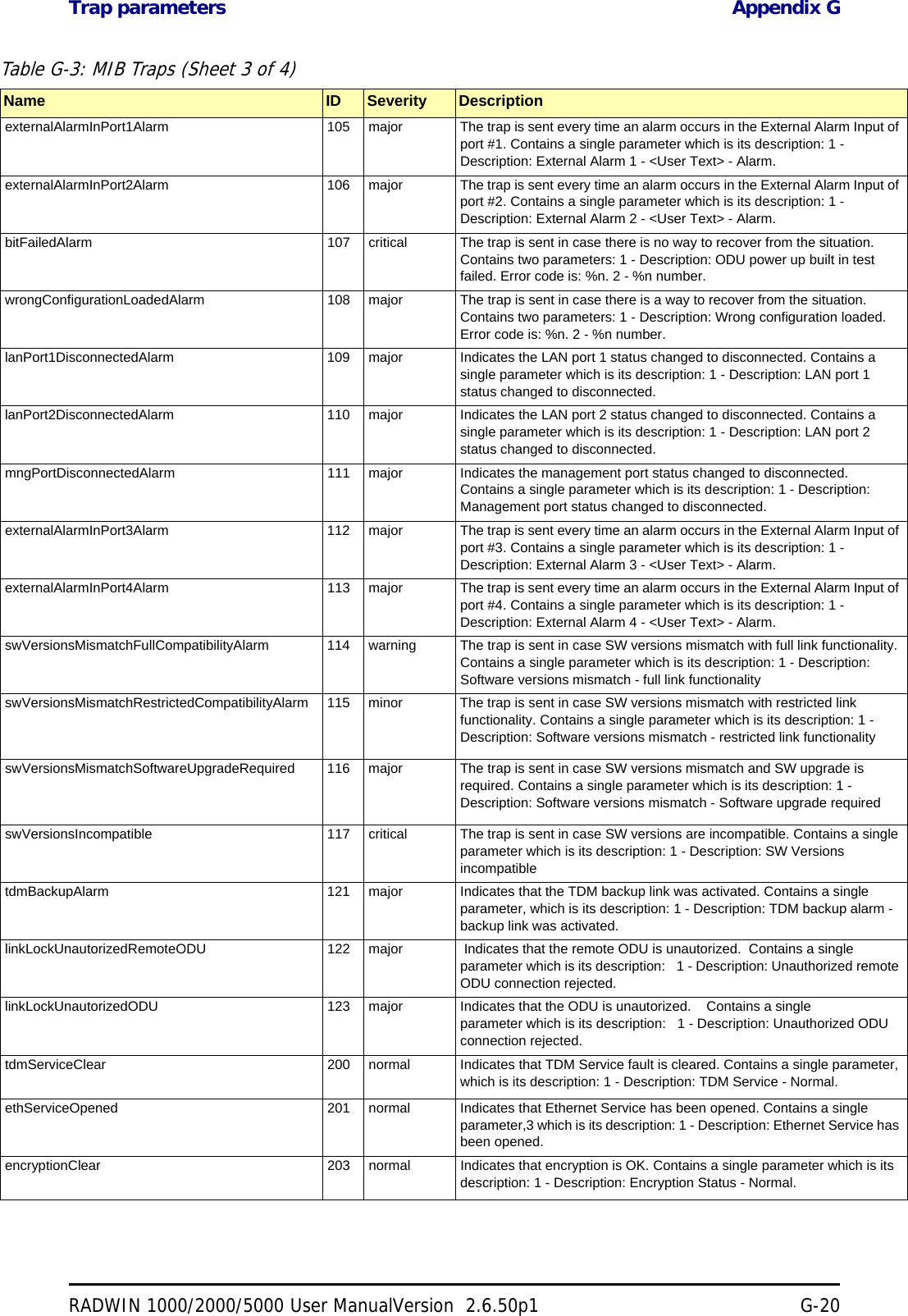
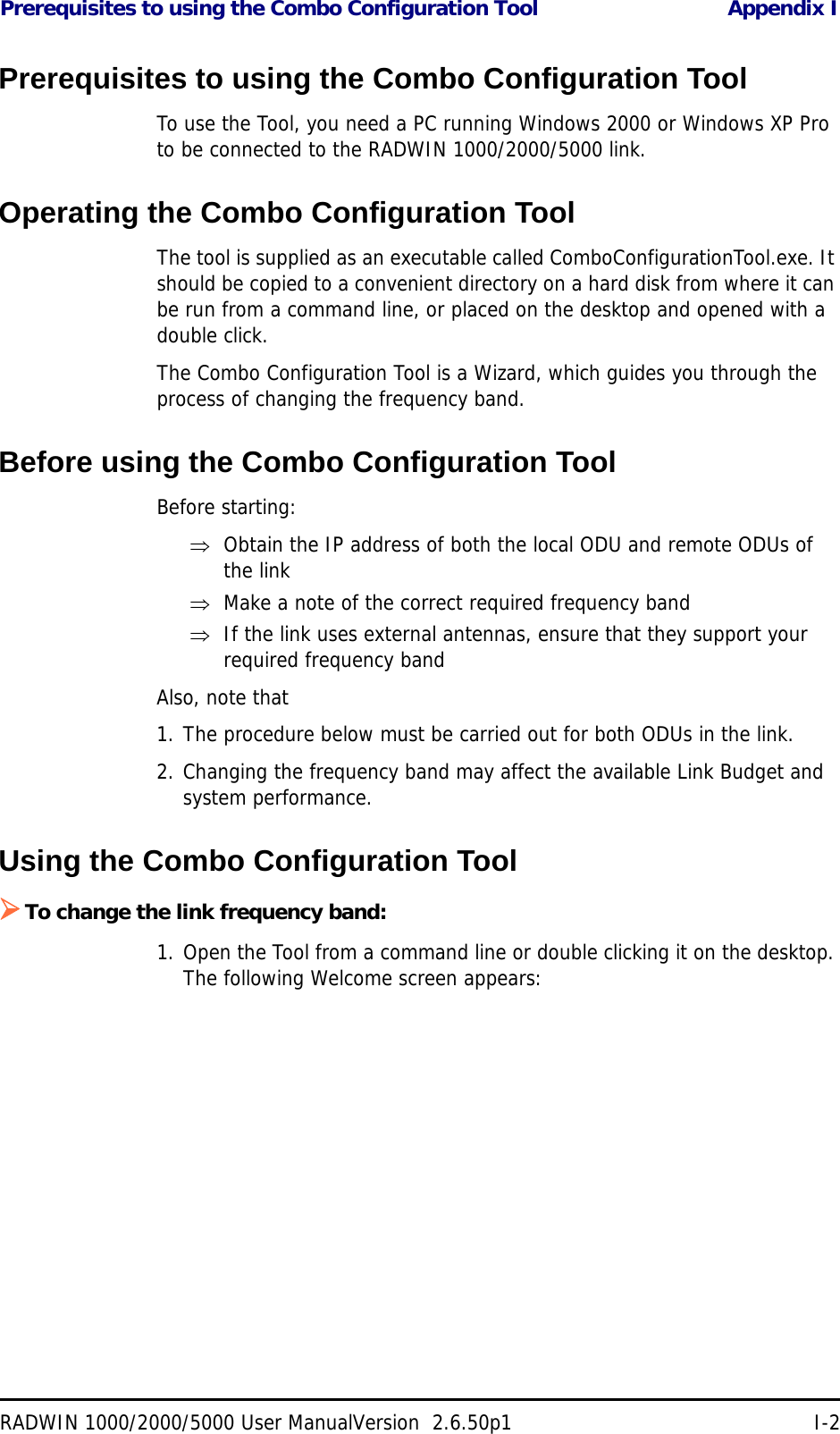
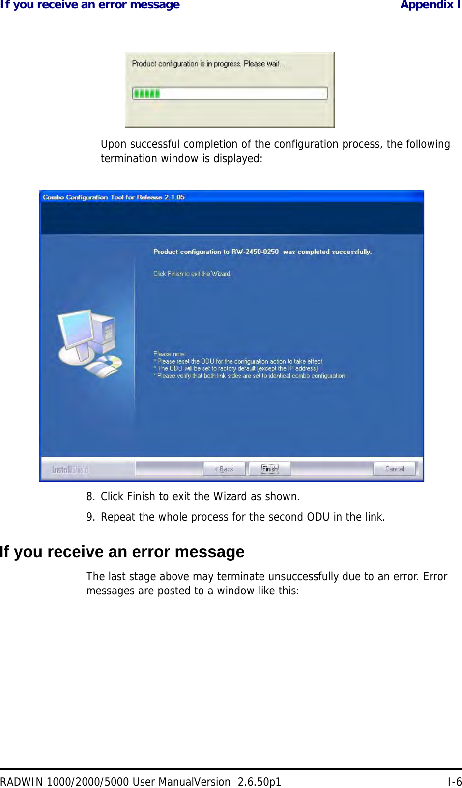
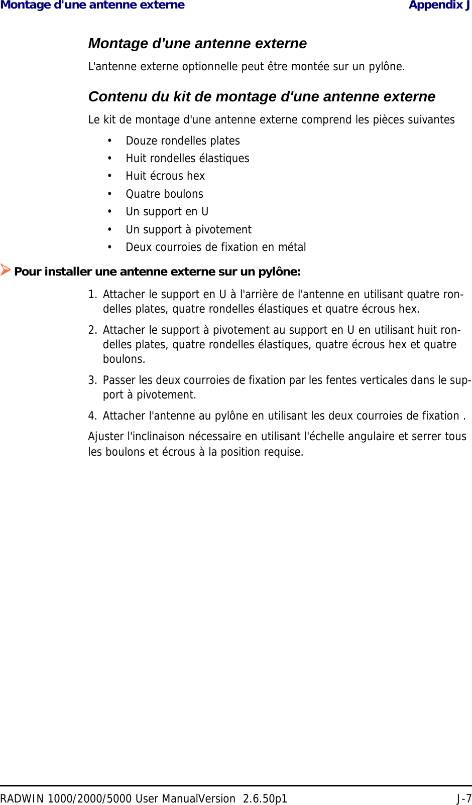
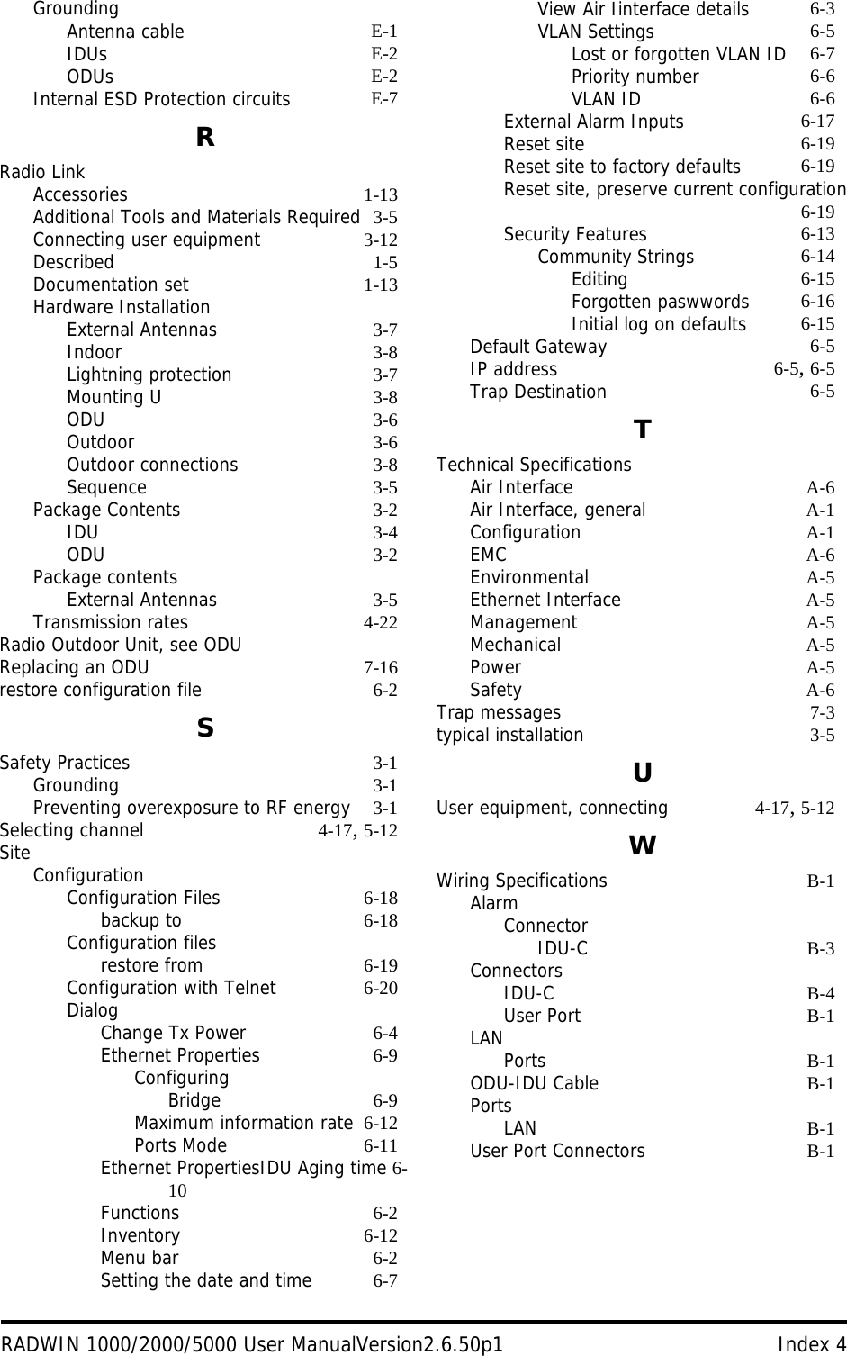
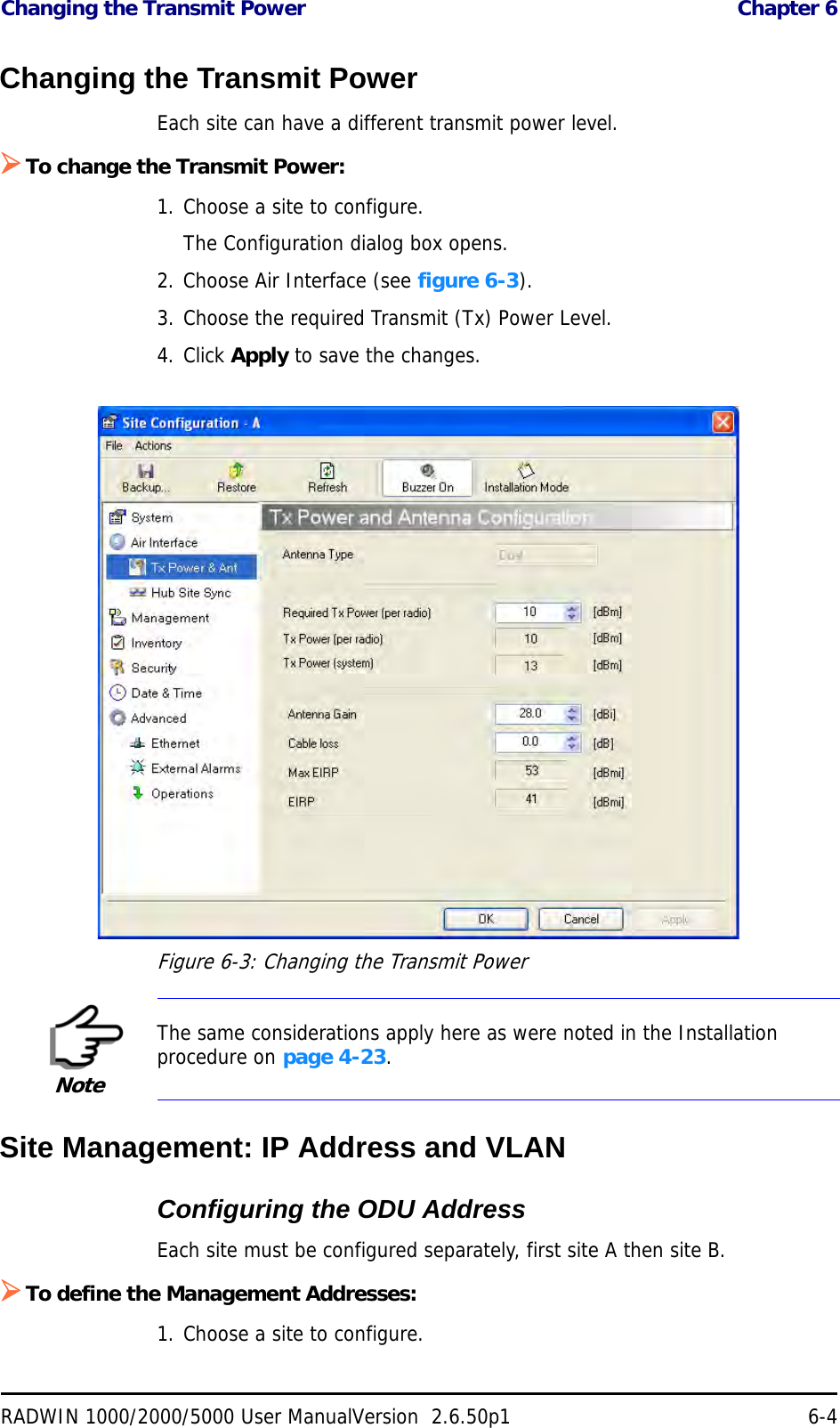
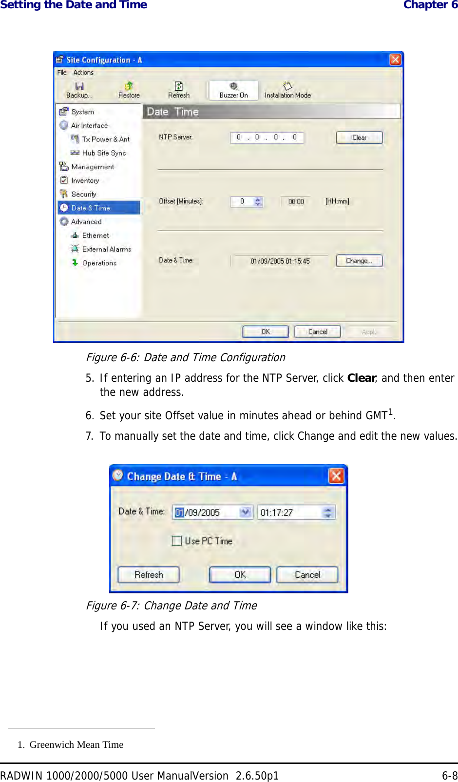
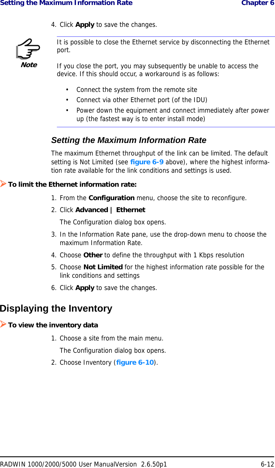
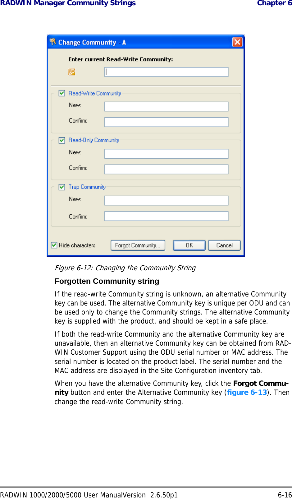
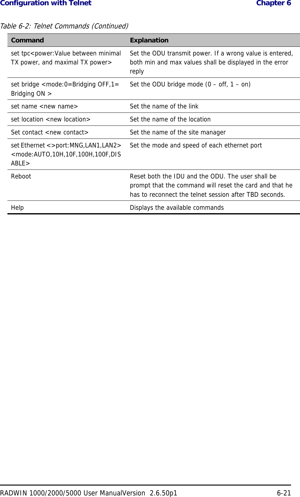
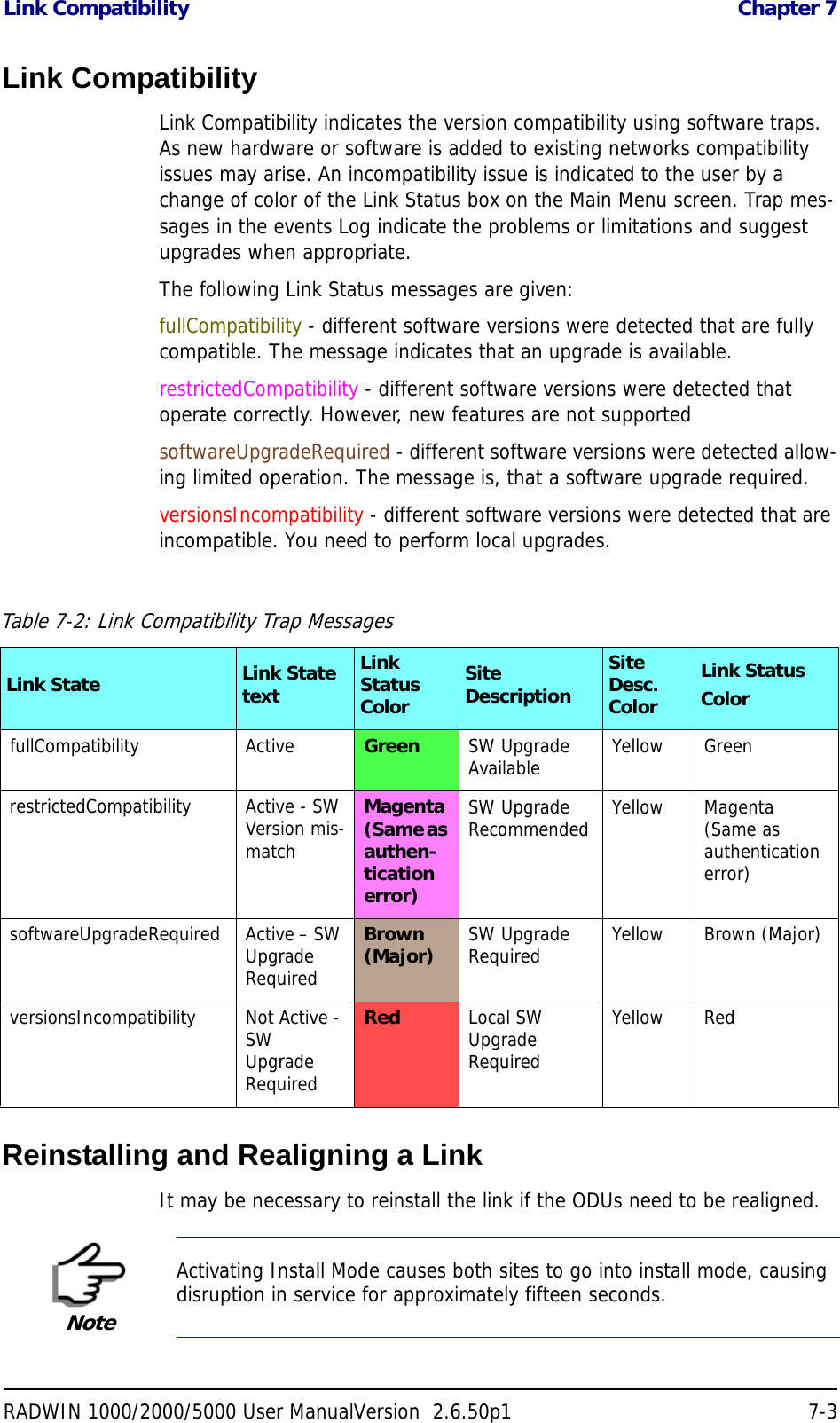
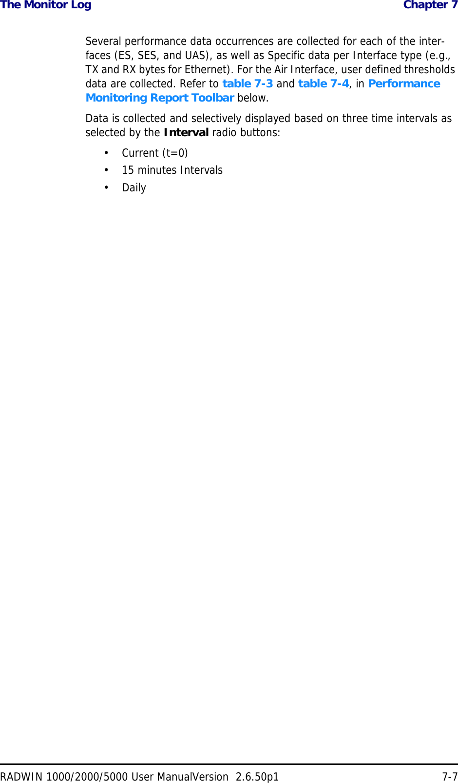
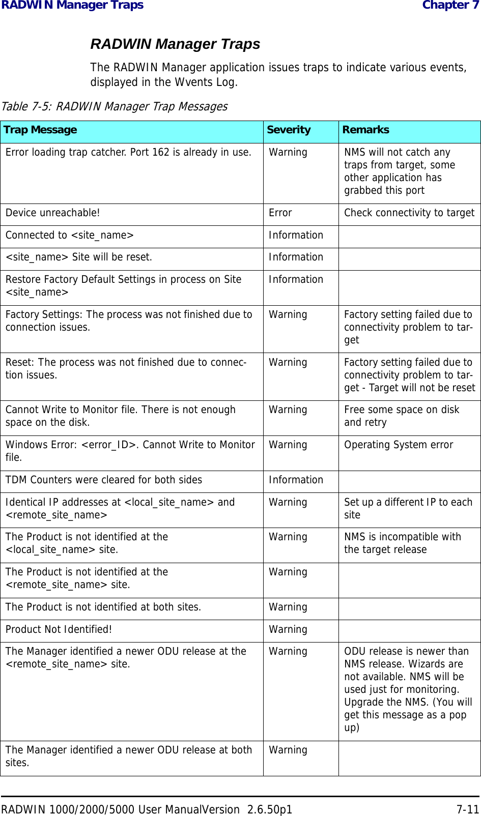
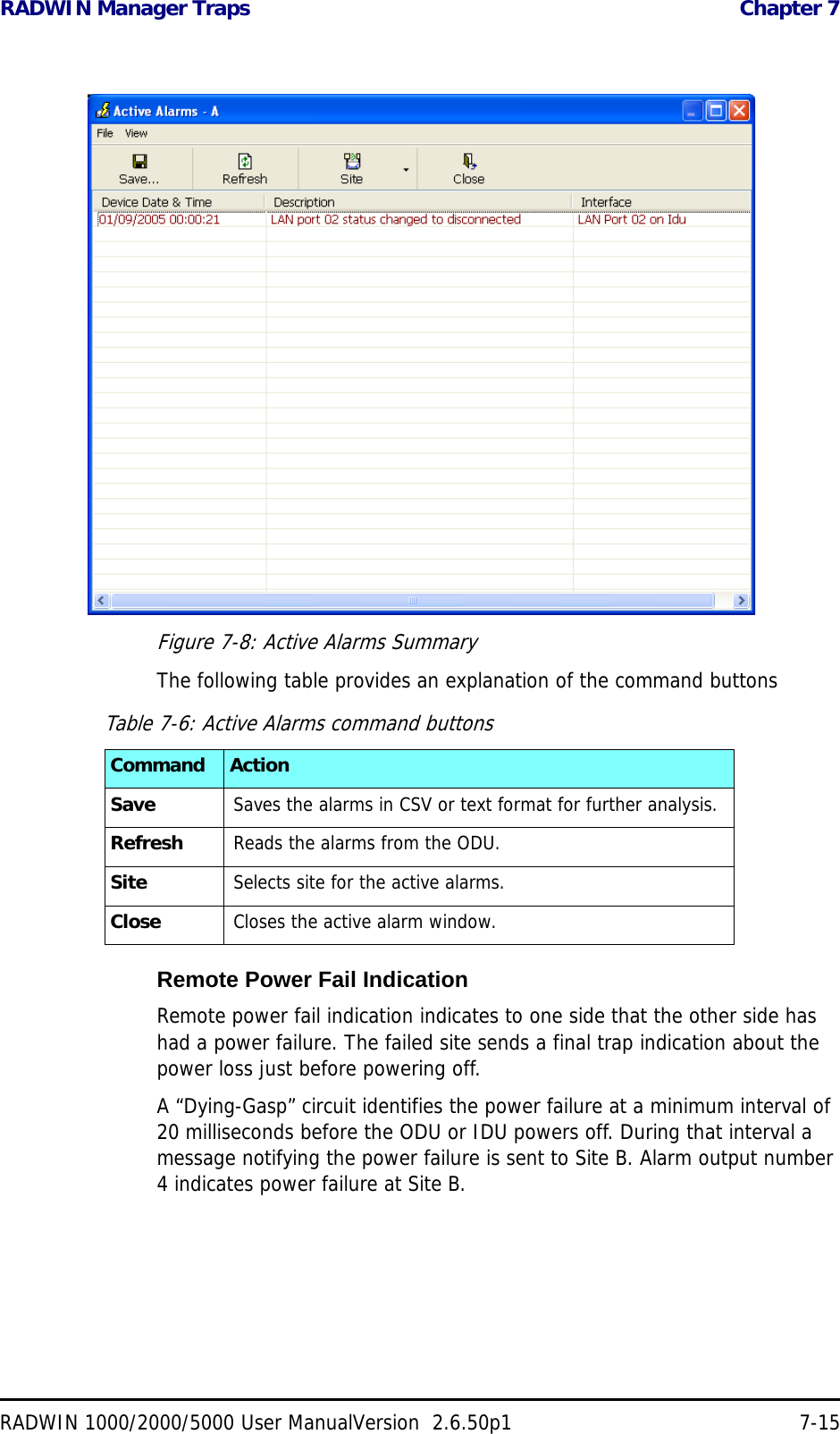
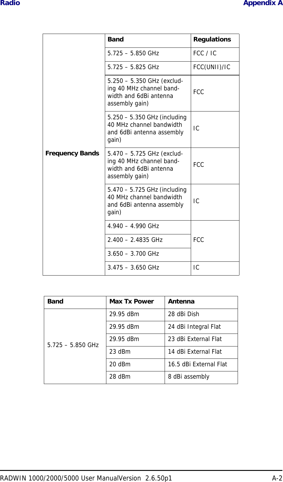
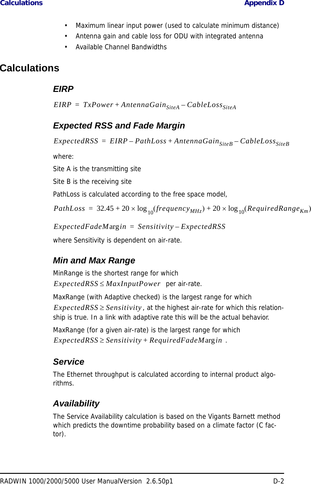
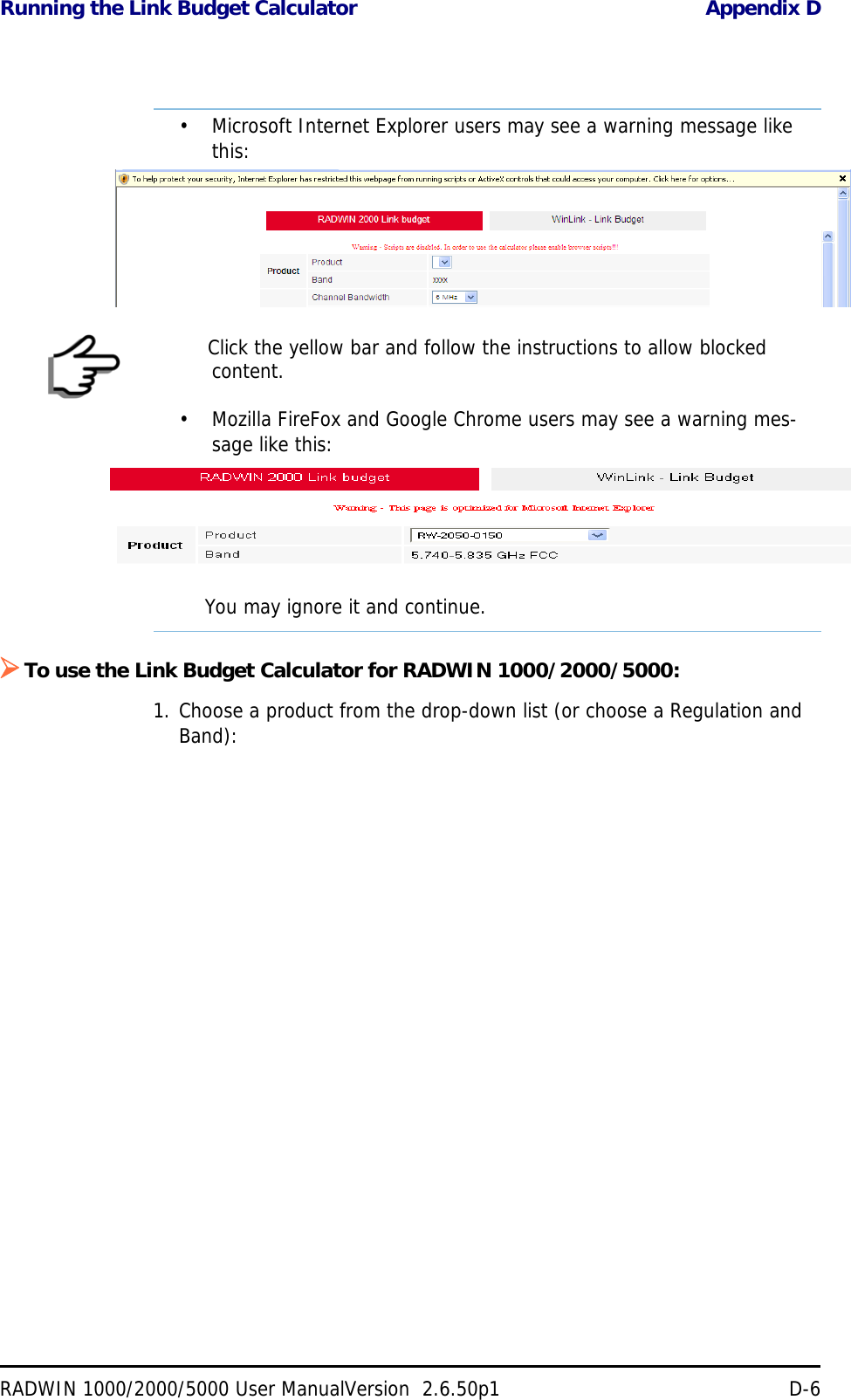
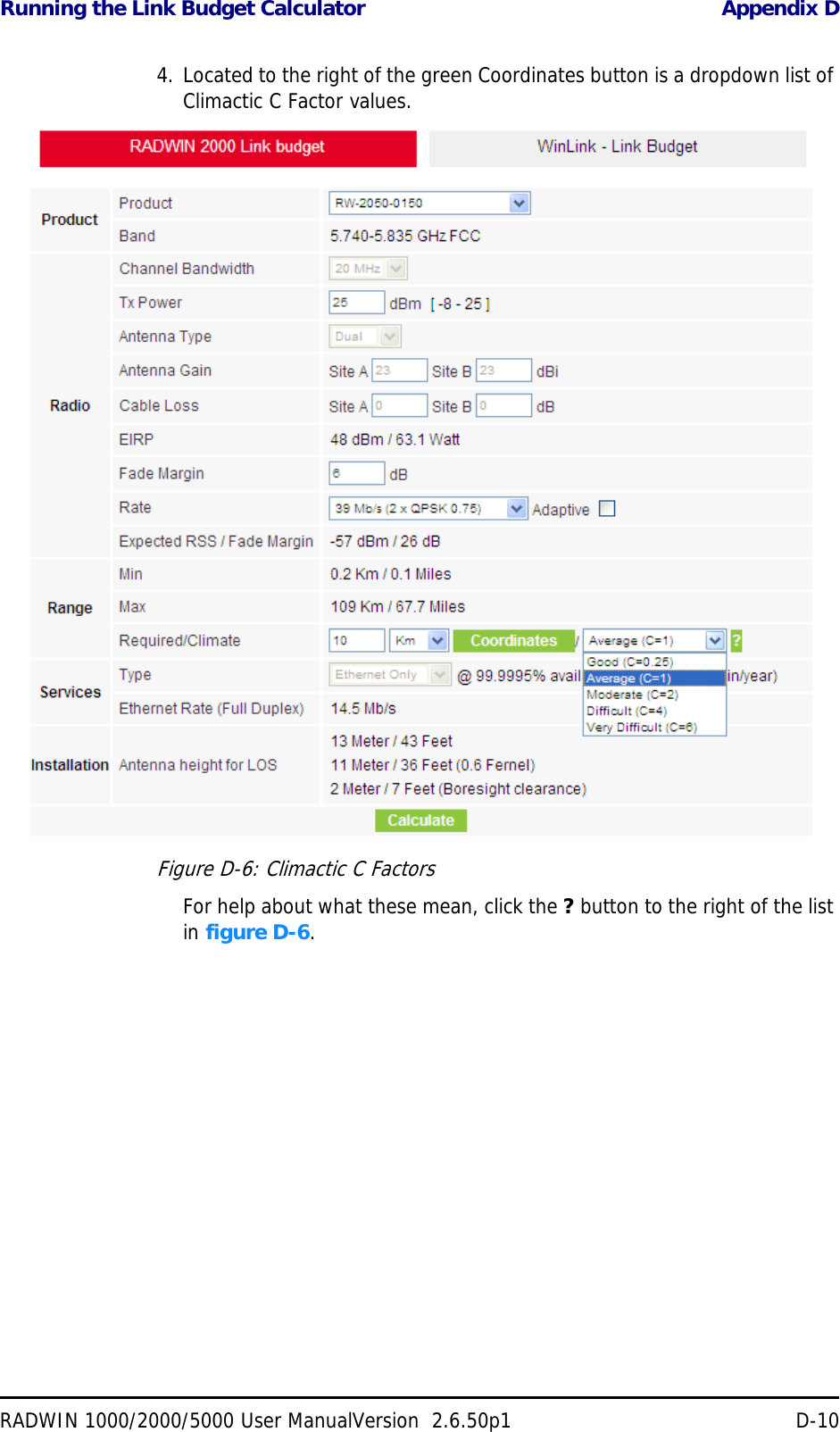
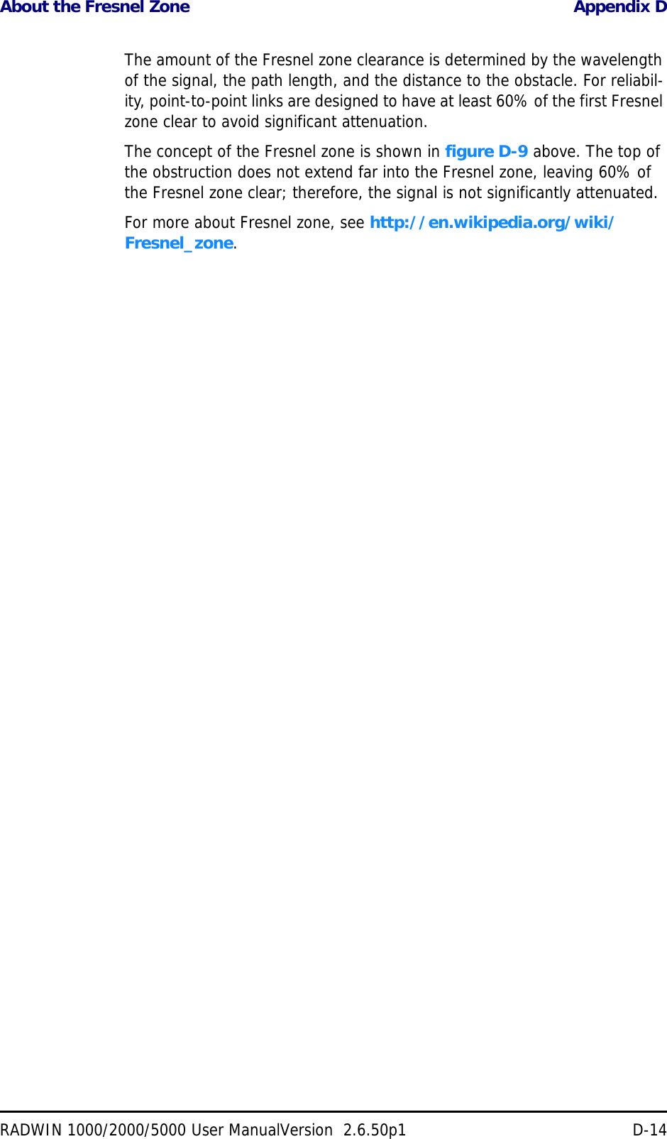
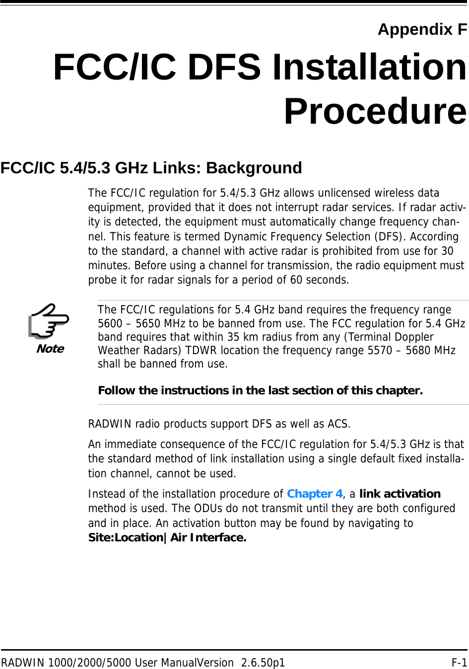
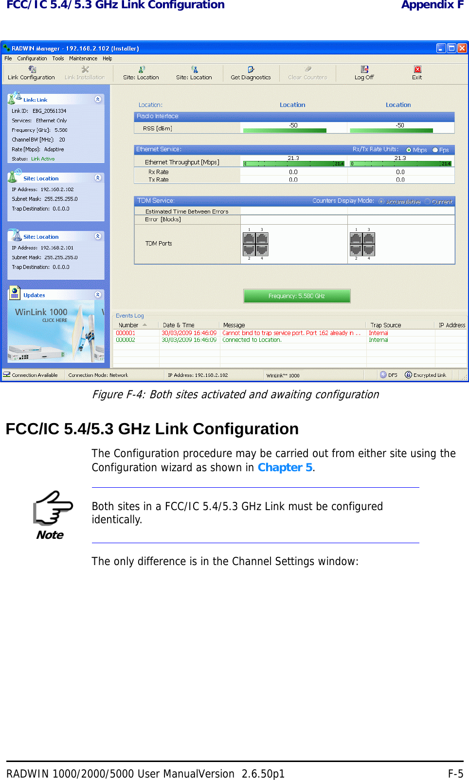
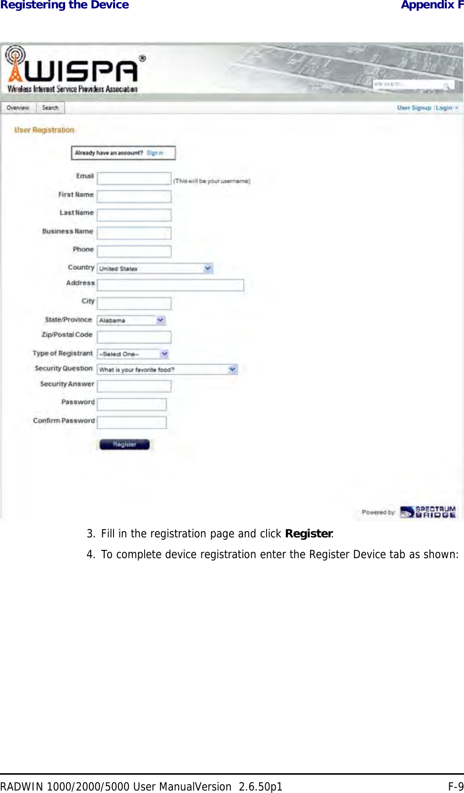
![TDWR Table Appendix FRADWIN 1000/2000/5000 User ManualVersion 2.6.50p1 F-12NV LAS VEGAS W 115 00 26 N 36 08 37 5645 MHz 1995 64 NY FLOYD BENNETT FIELD W 073 52 49 N 40 35 20 5647 MHz 8 97 OH DAYTON W 084 07 23 N 40 01 19 5640 MHz 922 97 OH CLEVELAND W 082 00 28 N 41 17 23 5645 MHz 817 113 OH COLUMBUS W 082 42 55 N 40 00 20 5605 MHz 1037 113 OK AERO. CTR TDWR #1 W 097 37 31 N 35 24 19 5610 MHz 1285 80 OK AERO. CTR TDWR #2 W 097 37 43 N 35 23 34 5620 MHz 1293 97 OK TULSA W 095 49 34 N 36 04 14 5605 MHz 712 113 OK OKLAHOMA CITY W 097 30 36 N 35 16 34 5603 MHz 1195 64 PA HANOVER W 080 29 10 N 40 30 05 5615 MHz 1266 113 PR SAN JUAN W 066 10 46 N 18 28 26 5610 MHz 59 113 TN NASHVILLE W 086 39 42 N 35 58 47 5605 MHz 722 97 TX HOUSTON INTERCONTL W 095 34 01 N 30 03 54 5605 MHz 154 97 TX PEARLAND W 095 14 30 N 29 30 59 5645 MHz 36 80 TX DALLAS LOVE FIELD W 096 58 06 N 32 55 33 5608 MHz 541 80 TX LEWISVILLE DFW W 096 55 05 N 33 03 53 5640 MHz 554 31 UT SALT LAKE CITY W 111 55 47 N 40 58 02 5610 MHz 4219 80 VA LEESBURG W 077 31 46 N 39 05 02 5605 MHz 361 113 WI MILWAUKEE W 088 02 47 N 42 49 10 5603 MHz 820 113 Table F-1: Latitude and longitude locations of TDWRs (Continued)STATE CITY LONGITUDE LATITUDE FREQUENCY TERRAIN ELEVATION (MSL) [ft] ANTENNA HEIGHT ABOVE TERRAIN [ft]](https://usermanual.wiki/Radwin/RW2030.Revised-User-manual-part-2/User-Guide-1570439-Page-85.png)