Ranger Communications ST-2112D Private land mobile radio User Manual
Ranger Communications (M) SDN. BHD. Private land mobile radio Users Manual
UserManual.wiki
>
Ranger Communications
>
ST 2112D User Manual
Users Manual
Navigation menu
Upload a User Manual
Namespaces
Wiki Guide
HTML
PDF
Info
Views
User Manual
Discussion / Help
Navigation
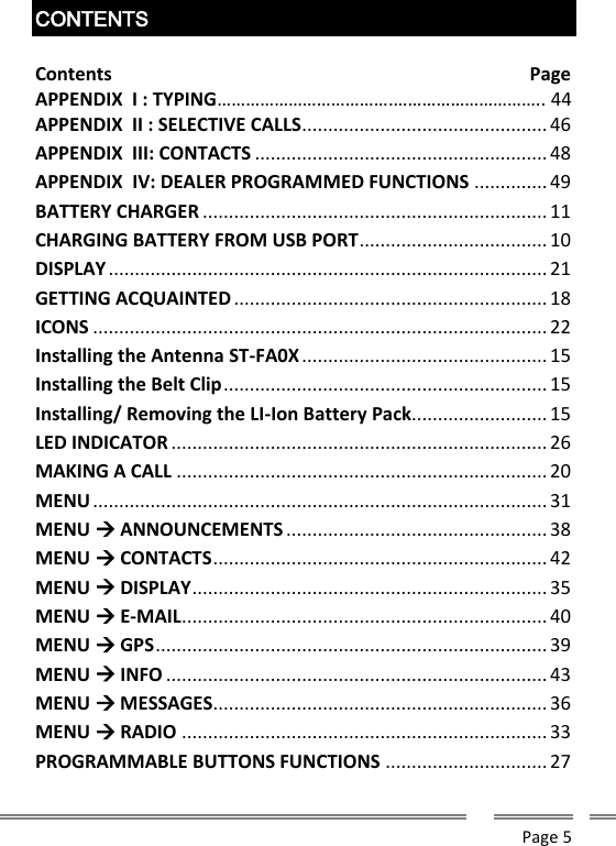

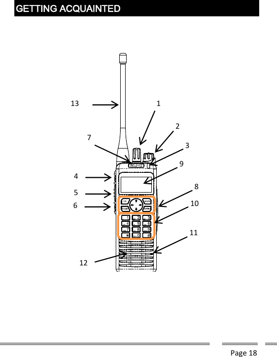
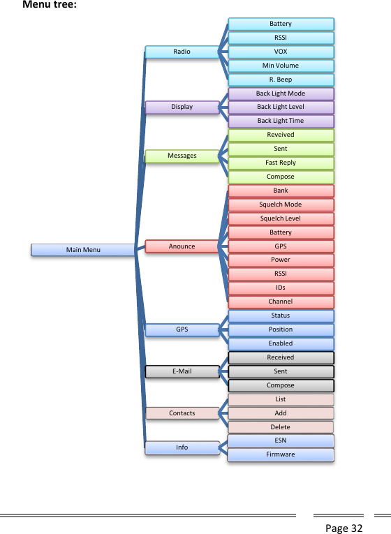
![Page 33 MENU RADIO Radio: This Submenu gives to the user the possibility of access the radio behavior, appearance and show status of it. Radio Battery: shows on the display the battery charge information, including percentage of charge and Time to Empty (TTE) estimated as per last two minutes average power demand. If the radio is on charge, TTE will be changed to Time to Full (TTF), as estimated time to complete the charge. This information will be continuously updated to the display. To exit this mode, press [MENU]. Radio continues in normal operational mode, but display will show this information instead any other related to the current channel and bank. Radio RSSI: shows on the display the Received Signal Strength (RSSI) continuously, expressed in –dBm. This information will be continuously updated to the display. To exit this mode, press [MENU]. Radio continues in normal operational mode, but RadioBatteryRSSIVOXEnabledOnOffLevel 0 .. 15Min Volume 0 .. 255R. BeepOnOff](https://usermanual.wiki/Ranger-Communications/ST-2112D/User-Guide-3186842-Page-33.png)
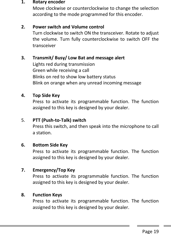
![Page 34 display will show this information instead any other related to the current channel and bank. Radio VOX: This option lets you to enable the Voice Operated Transmit control. If your radio has an external microphone connected to the external microphone input, then you can enable this option. Radio VOX Enable: Select this option to enable or disable the VOX operation. Once selected this step by pressing [OK], you will see the actual VOX status. To toggle current status use [UP] or [DOWN] arrow key, then save your selection by pressing [OK] Radio VOX Level: Select this option by pressing [OK] to adjust the threshold level of voice into your microphone to switch the radio to transmit mode. Once you enter on level alignment mode, use [UP] or [DOWN] arrow keys to adjust it to your desired value between 0 and 15. Radio Min Volume: Use this option to adjust the minimum volume level of your radio, even when the volume knob is at minimum. Once selected this menu step, use [UP] and [DOWN] arrow keys to select your desired level (0..255). Once selected the right volume, press OK to store it and go back to the Radio Menu. To exit, press [MENU]. Radio R. Beep: This option lets you to activate a beep tone to be sent over the air to other parties each time you release the PTT (Roger Beep). Use [up] or [DOWN] arrow keys to enable (ON) or disable (OFF) this feature, the press [OK] to store it. To exit, press [MENU].](https://usermanual.wiki/Ranger-Communications/ST-2112D/User-Guide-3186842-Page-34.png)
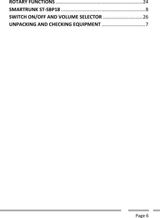
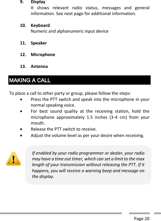
![Page 35 MENU DISPLAY Display: This Submenu gives to the user the possibility of adjust the behavior of the radio display, backlight levels and timeouts. Display BL Mode: this step lets you select the back light operation mode. Use [UP] or [DOWN] arrow keys to enable (ON) or disable (OFF) or select (Auto) mode. Press [OK] to store it. To exit, press [MENU]. Display BL Mode Auto: Automatically controls the behavior of display backlight. The backlight will be turned ON if any key is pulsed or an incoming signaling matches the radio ID and automatically turned OFF after a programmable timeout. Display BL Mode On: Display backlight will be all time on. This feature is not efficient form battery saving point of view. Display BL Mode Off: Display Backlight never goes ON. Display BL Level: this step lets you select the back light bright. Use [UP] or [DOWN] arrow keys to adjust your desired bright (0 .. 15). DisplayBack Light ModeAutoOnOffBack Light Level 0 .. 15Back Light Time 0 .. 15](https://usermanual.wiki/Ranger-Communications/ST-2112D/User-Guide-3186842-Page-35.png)
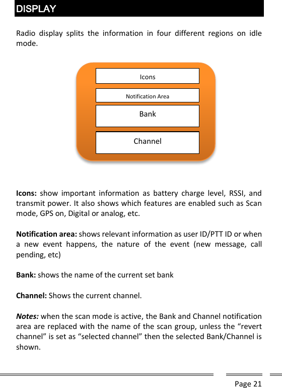
![Page 36 Press [OK] to store it. To exit, press [MENU]. Display BL Time: this step lets you select the back light timeout. Use [UP] or [DOWN] arrow keys to adjust your desired timer from 0 to 15 seconds. Press [OK] to store it. To exit, press [MENU]. MENU MESSAGES Message: this step will give you full access to the messaging capabilities. Send, Receive, compose, and fast reply. Message Received: Use this option to read incoming messages. As soon as you press OK on this option, the display will show the latest incoming message. Scroll through all the list of incoming messages by pressing [UP] or [DOWN] arrows. Once you focus on the desired message, press [OK] to read it fully. MessagesReceivedSent ReviewResendForwardDeleteFast ReplyComposeNote: The message feature is only available for any of the digital modes (FDMA or TDMA) and the user can only access to it if current channel is a digital one.](https://usermanual.wiki/Ranger-Communications/ST-2112D/User-Guide-3186842-Page-36.png)
![Page 37 To exit, press [MENU]. Message Sent: Select this option to review all sent messages. As soon as you press OK on this option, the display will show the latest message sent from your radio. Scroll through all the list of sent messages by pressing [UP] or [DOWN] arrows. Once you focus on the desired message, press [OK] to read it fully. Press [OK] once more to get the message sent sub-menu, then choose the desired option: Resend, Forward or Delete it. Message Sent Resend: Automatically resend the message to the same destination. Message Sent Forward: lets you edit the message then, as soon as you press [OK] the radio ask to input the destination ID for the message. Use the keyboard to type the destination ID then press [OK] to send it. Message Sent Delete: Choose this option to erase the current message from memory. Once you select the right message, select this option, then you will be asked to confirm the action. You must press [OK] to confirm it or press [BACK] to jump one step back into the menu tree. Message Fast Reply: Choose this option to send a message from a pre-recorded list to any ID. Once you press [OK], you will see the list of pre-recorded messages enabled by your dealer. Use [UP] and [DOWN] arrow keys to scroll the list. Once focused the right one, press [OK] to confirm or [MENU] to exit. Once you select the right message, input the destination ID and press [OK] to send it. Message Compose: Use this option to create a new message to be sent. Once you press [OK], you will get the complete display to type the message using the keyboard.](https://usermanual.wiki/Ranger-Communications/ST-2112D/User-Guide-3186842-Page-37.png)
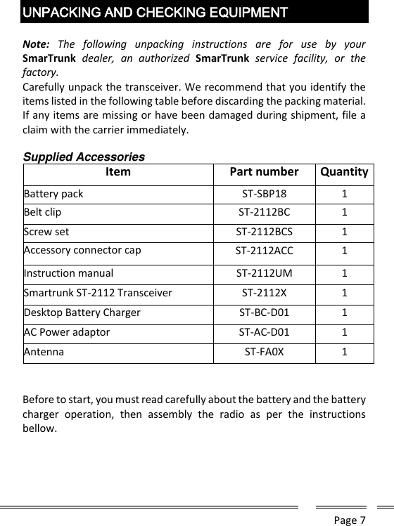
![Page 38 Press OK once the complete message has been written, then the radio will ask you to type the destination ID for the message. Press [OK] to send it after the ID has been typed. After few seconds you will receive the message sent status (sent OK, failed or delayed) MENU ANNOUNCEMENTS Announce: Allows the user to the enable or disable the radio announces. Navigate, using [UP] and [DOWN] arrow keys, through the list of announcement to be activated or deactivated , then press [OK] to access to the programming mode. Use [UP] and [DOWN] arrow keys to switch the announcement feature ON or OFF then press [OK] to confirm the selection. Announce Bank: announce the current bank number. Played back each time you change the current bank. Announce Squelch: Announces the current squelch mode. Played back each time you change the squelch mode. Announce Battery: Announces the actual battery status, including the remaining charge in percentage and the time to finish the charge as per AnounceBankSquelch ModeSquelch LevelBatteryGPSPowerRSSIIDsChannel](https://usermanual.wiki/Ranger-Communications/ST-2112D/User-Guide-3186842-Page-38.png)
![Page 39 the average of the last two minutes of current demand. It is played back when you press a programmed button to check battery level. Announce GPS: it announces the status of the GPS (ON or OFF). It is played back when you press a programmed button to change GPS status. Announce Power: It announces the current transmit power (High, Med, Low or Auto). It is played back when you press a programmed button to adjust the transmit power. Announce RSSI: It announces the current RSSI level when receiving an analog carrier or an FDMA carrier. It is played back when you press a programmed button to check the RSSI. Announce IDs: It announces the caller ID at the front of an incoming private call (Only on trunking mode). Announce Channel: It announces the current channel number on current bank. It is played back only when you change the channel. MENU GPS GPS: Lets you to adjust current GPS status (on/off), shows the status of the GPS receiver and the current position if fixed. GPS Status: Shows on display the quantities of satellites used to fix. In case of not fixed yet, it will show NOT FIXED or GPS Disabled. To exit this screen press [MENU] or [BACK] to jump to GPS Menu root. GPSStatusPositionEnabled](https://usermanual.wiki/Ranger-Communications/ST-2112D/User-Guide-3186842-Page-39.png)
![Page 40 GPS Position: If fixed, it shows on display the coordinates in latitude and longitude of current location. To exit this screen press [MENU] or [BACK] to jump to GPS Menu root. GPS Enabled: lets you manually enable or disable the GPS on you radio (Only for ST-211xy-AG versions). Use [UP] or [DOWN] arrows to enable or disable the GPS then press OK to confirm you selection. Setting the GPS engine OFF will reduce the energy demand. MENU E-MAIL E-Mail: Use this menu to create, read and send E-mails. E-Mail Received: Use this option to read incoming e-mails. As soon as you press OK on this option, the display will show the latest incoming e-mail. Scroll through all the list of incoming e-mail by pressing [UP] or [DOWN] arrows. E-MailReceivedSentComposeNote: The e-mail feature is only available for any of the digital modes (FDMA or TDMA) and the user can only access to it if current channel is a digital one. ST-9116 or ST-9118 repeater with e-mail server engine must be present into your infrastructure and the service must be allowed for your radio ID on the way to send or receive e-mails.](https://usermanual.wiki/Ranger-Communications/ST-2112D/User-Guide-3186842-Page-40.png)
![Page 41 Once you focus on the desired e-mail, press [OK] to read it fully. To exit, press [Menu]. E-Mail Sent: Select this option to review all sent e-mails. As soon as you press OK on this option, the display will show the latest e-mail sent from your radio. Scroll through all the list of sent e-mails by pressing [UP] or [DOWN] arrows. Once you focus on the desired e-mail, press [OK] to read it fully. Press [OK] once more to get the e-mail sent sub-menu, then choose the desired option: Resend, Forward or Delete it. E-mail Sent Resend: Automatically resend the e-mails to the same destination. E-mail Sent Forward: lets you edit the e-mail then, as soon as you press [OK] the radio ask to input the destination ID for the e-mail. Use the keyboard to type the destination e-mail address then press [OK] to send it. E-Mails Sent Delete: Choose this option to erase the current e-mail from memory. Once you select the right e-mail, select this option, then you will be asked to confirm the action. You must press [OK] to confirm it or press [BACK] to jump one step back into the menu tree. E-Mail Fast Reply: Choose this option to send a message from a pre-recorded list to any e-mail address. Once you press [OK], you will see the list of pre-recorded messages enabled by your dealer. Use [UP] and [DOWN] arrow keys to scroll the list. Once focused the right one, press [OK] to confirm or [MENU] to exit. Once you select the right message, input the destination e-mail address and press [OK] to send it. E-Mail Compose: Use this option to create a new e-mail to be sent.](https://usermanual.wiki/Ranger-Communications/ST-2112D/User-Guide-3186842-Page-41.png)
![Page 42 Once you press [OK], you will get the complete display to type the e-mail using the keyboard. Press [OK] once the complete e-mail has been written, then the radio will ask you to type the destination e-mail address for the message. Press [OK] to send it after the address has been typed. After few seconds you will receive the e-mail sent status (sent OK, failed or delayed) MENU CONTACTS Contacts: Access to the phone book of your radio. Contacts List: list down all contacts defined in your radio phone book. Scroll through all the list of contacts by pressing [UP] or [DOWN] arrows. Once you focus on the desired contact name, press [OK] to select it. Once selected, you can address a private call to the selected contact by pressing PTT. To exit, press [MENU]. Contacts Add: Select this option to add a new contact to your phone book. Type the contact information by using the keyboard. Once you finish, press [OK] then complete the ID number or e-mail address for that contact. Press [OK] to save it in memory or [MENU] to escape. Contacts Delete: list down all contacts defined in your radio phone book. Scroll through all the list of contacts by pressing [UP] or [DOWN] ContactsListAddDelete](https://usermanual.wiki/Ranger-Communications/ST-2112D/User-Guide-3186842-Page-42.png)
![Page 43 arrows. Once you focus on the desired contact name, press [OK] to select it then you will be asked to confirm the delete action by pressing [OK] or escape from this option by pressing [MENU] MENU INFO Info: radio information a Firmware Version and Serial Number. Info ESN: Temporary shows the Electronic Serial Number of your unit. Press [MENU] to exit or wait for the time-out. Info Firmware: Temporary shows the firmware release loaded into your radio. Press [MENU] to exit or wait for the time-out. Info ESNFirmware](https://usermanual.wiki/Ranger-Communications/ST-2112D/User-Guide-3186842-Page-43.png)
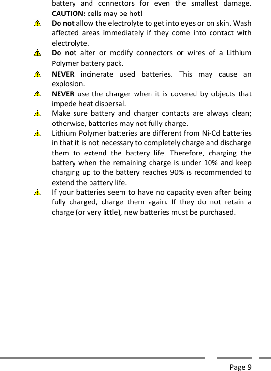
![Page 44 APPENDIX I : TYPING Anytime you must type a message or contact name, you must use radio keyboard. Each key, when the radio is on typing mode, add one character to your text on cursor position. By pressing the same key repeatedly within a second, you can choose the new character to add with some key in agree to the following table: KEY CHARACTER 1 1 ! , ~ % 2 a b c A B C 2 ” 3 d e f D E F 3 # 4 g h I G H I 4 $ 5 j k l J K L 5 % 6 m n o M N O 6 & 7 p q r s P Q R S 7 8 t u v T U V 8 ( 9 w x y z W X Y Z 9 * * . - + / ) ’ ^ 0 [space] 0 _ < > ° ; : # # ; | To move the writing cursor to the Right/Left press the navigation key [RIGHT]/[LEFT] To jump the previous/next line, press the navigations key [UP]/[DOWN] To delete a char press the [BACK] key](https://usermanual.wiki/Ranger-Communications/ST-2112D/User-Guide-3186842-Page-44.png)
![Page 45 To finish the Message and send it, press the [OK] Key. To leave the message press [MENU] Key.](https://usermanual.wiki/Ranger-Communications/ST-2112D/User-Guide-3186842-Page-45.png)
![Page 46 APPENDIX II : SELECTIVE CALLS Some radio mode supports selective calling (Analog MDC, digital TDMA or Digital FDMA). By this reason, your radio has an associated ID. If your radio has been programmed with this feature, you will see your ID into the display notification area. In case you see only one ID into this area, then it means your radio is in all-call mode, which means your transmission will be received by all your partners each time you press the PTT. If you wish to make a selective call, then you have two options: A – Type the destination ID from the Keyboard then press [OK] B – Select the destination ID from radio’s phone book then press [OK] Any of the modes you choose, lets you address all your transmission to only one user. Destination ID could be also a group ID. After you select an ID, you can see the destination of your transmissions into the display’s notification area (for example 1001/1002). In case your destination ID is on your phone book, you can read the contact name into display’s notification area (for example 1002/Emily). To receive a selective call, a destination radio must have the selective call enabled. If so, only the enabled radio will receive each one of your transmissions when you press the PTT under a selective call mode.](https://usermanual.wiki/Ranger-Communications/ST-2112D/User-Guide-3186842-Page-46.png)