Ranger Communications ST-3118V Private land mobile radio User Manual
Ranger Communications (M) SDN. BHD. Private land mobile radio
UserManual.wiki
>
Ranger Communications
>
ST 3118V User Manual
User manual
Navigation menu
Upload a User Manual
Namespaces
Wiki Guide
HTML
PDF
Info
Views
User Manual
Discussion / Help
Navigation
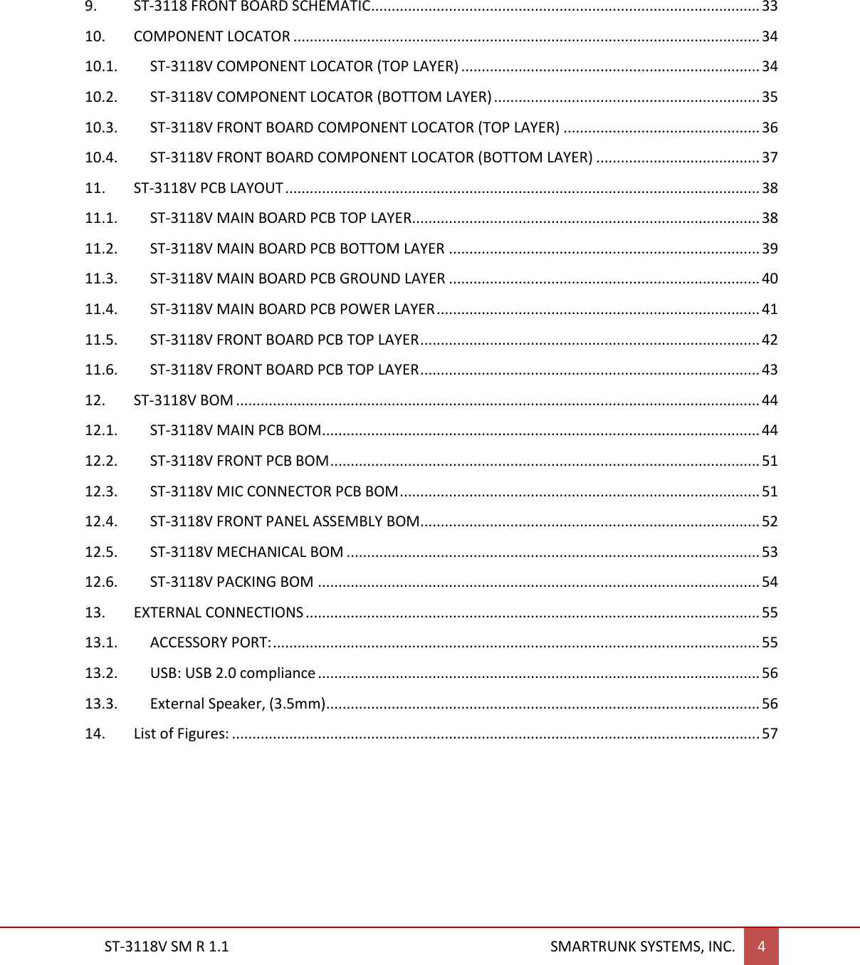
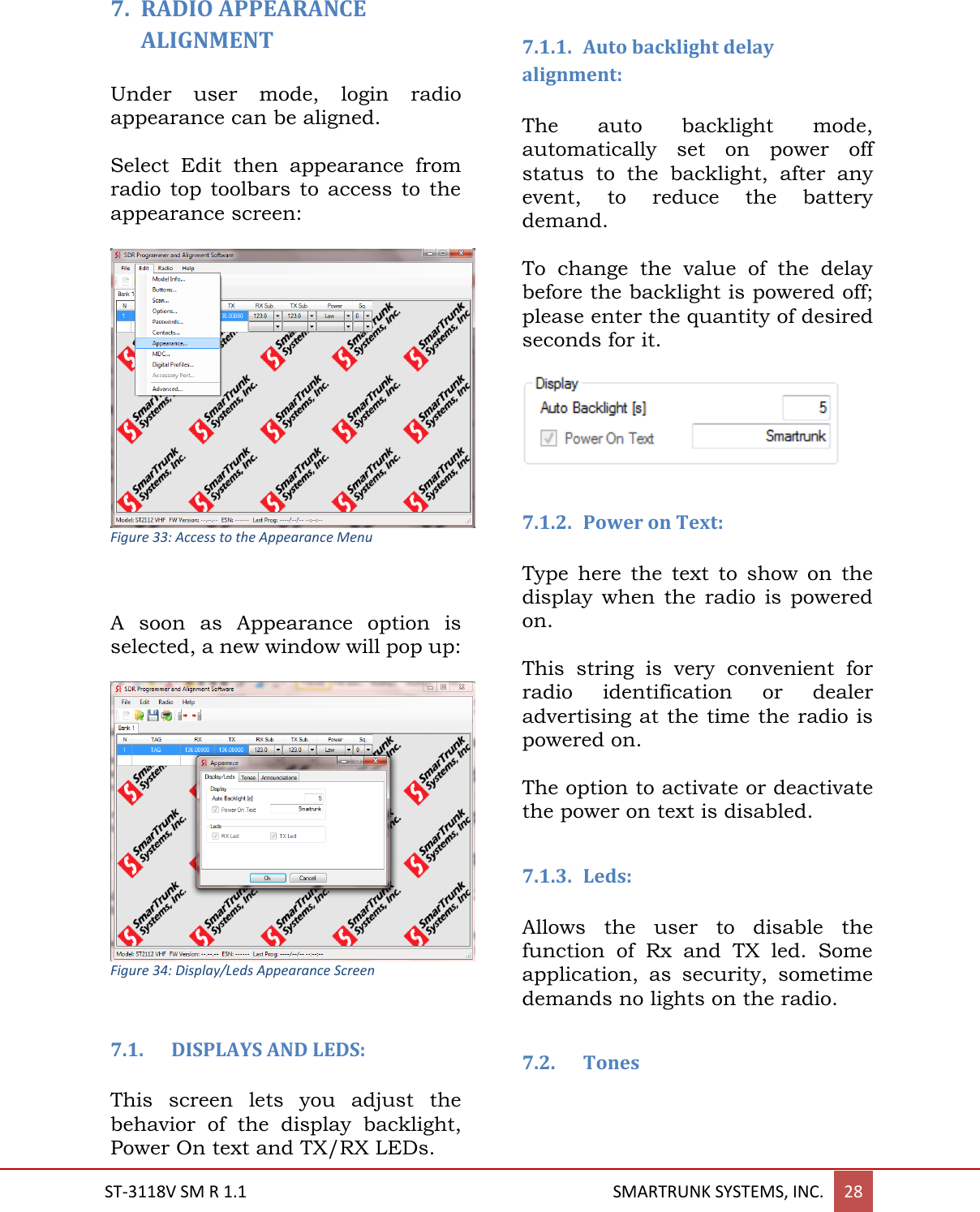
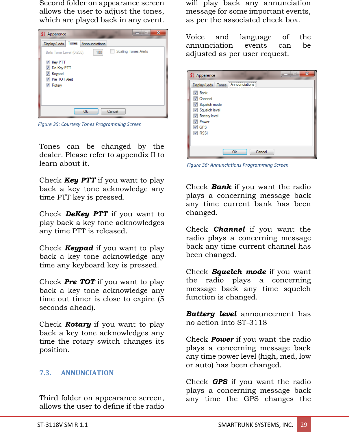
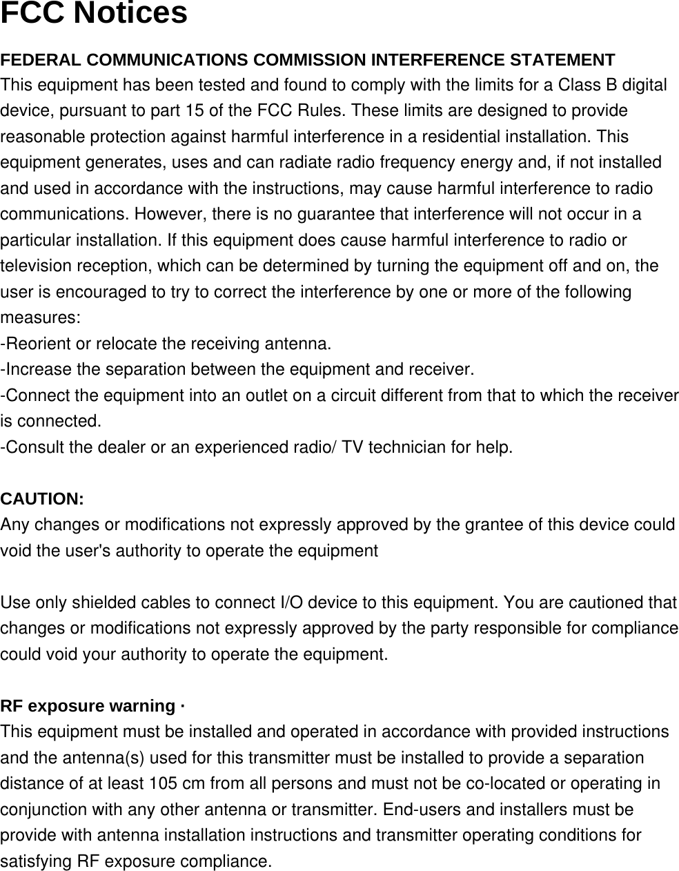
![4. - ST-3118 RF DESCRIPTION 4.1. Circuit Configuration The receiver is a single receiver with built DSP fully integrated. Incoming signals from the antenna, after passing through LPF filter, are fed direct to the DSP down converter to get the baseband voice from 0Hz to 3500Hz. Demodulated signals are filtered and conditioned onto a second DSP based filter, which also includes a high efficiency 4FSK modem. For digital demodulation, the recovered data is fed into a vocoder, which converts the data to voice. Analog voice form the analog path or the analog voice recovered from the vocoder are fed into an audio power amplifier. The transmit signal frequency is generated by the integrated VCO and PLL. RF frequency generated by the integrated RF chip is amplified into a 3-step amplifier then filtered by a low pass filter to be applied to the antenna. 4.2. Receiver System 4.2.1. Front-end RF Receiver Incoming RF signals from the antenna are delivered to the Receiver Unit and pass through a Low-pass filter, antenna switching diodes, and then fed to the receiver (U2) passing through a limiter BPF. 4.2.2. ANALOG Audio Processing The RF signal is tuned by U2, which includes a base band DSP audio processing, recovering flat audio from DC up to 3500 hz. The detected audio is amplified, filtered and conditioned inside of U12 which also includes a de-emphasize filtering shape for received audio signals The output of the filtered and conditioned audio is delivered to a power amplifier (U8) then to the speaker passing through the external audio connector switch. 4.2.3. Virtual Squelch Circuit RSSI is measured by the receiver (U2) as the result of the analysis of the signal and the noise of the carrier. The output is sent to the main processor (U13) as a digital frame, which is analyzed by radio firmware. If the signal quality is higher than the expected for the current programmed squelch threshold, then the processor LPF SWITCH PROTECTION FILTER RECEIVER [U2] RECEIVER [U2] AUDIO PROCESSOR [U12] AMPLIFIER [U8] Figure 1: Receiver block Diagram Figure 2: Receiver Analog Audio Path Bloc Diagram](https://usermanual.wiki/Ranger-Communications/ST-3118V/User-Guide-2891402-Page-6.png)
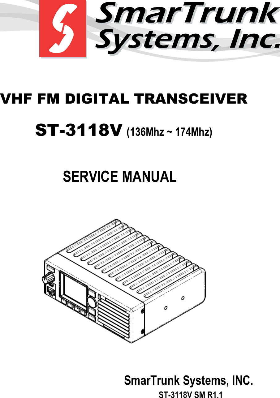
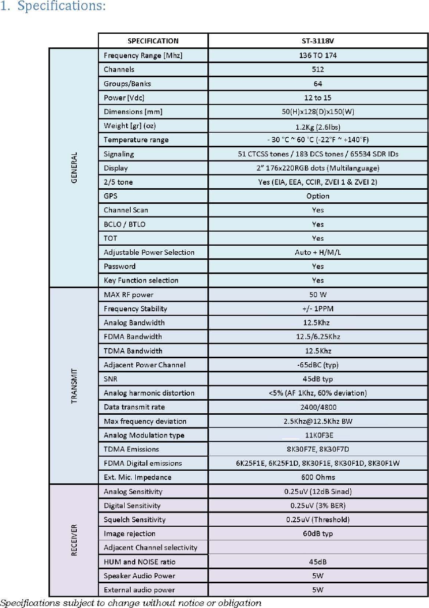
![ST-3118V SM R 1.1 SMARTRUNK SYSTEMS, INC. 9 analyzes the expected signaling programmed on the current channel table. In case of not any additional signaling must be decoded, or the signal has been detected, the main processor (U13) asks to the audio processor (U12) to open the audio path, unmuting the audio amplifier (U8). 4.2.4. Virtual VOLUME CONTROL The potentiometer position (R15 – front board) is measured by one analog to digital converter on the audio processor (U12), and then the information is reported to the main processor. The firmware immediately adjusts the audio processor path gain to get the appropriate overall circuitry volume control. Minimum volume, emergency and private audio level are controlled only by software overriding the information received from the DAC on U12. 4.2.5. Sub audio signaling Received sub audio signaling, as CTCSS and DCS, are received and processed by the receiver (U2) then detected on the audio processor (U12). Once decoded, the sub audio signaling is reported to the processor where the firmware compares it with the programmed into the current channel programming. If the received signaling matches the channel programming, then the main processor (U13) requests the audio processor (U12) to open the audio patch. 4.2.6. ANALOG AUDIBLE SIGNALING DTMF signals, MDC1200 and tone signals are processed and decoded by the audio processor (U12). Decoded information or received tone is reported to the main processor (U13). 4.2.7. DIGITAL AUDIO PROCESSING Digital received information is processed by the receiver DSP (U2) then delivered to the audio processor (U12), which includes a high-speed modem. Data decoded by the modem is transferred to the main processor (U13) which de-encrypts the information, checks the integrity, correct the wrong bits and extract the audio information form the received frame. The portion of the data received, error free, is moved to the vocoder (U14). The vocoder re-builds the audio from the compressed data then applies filters, adjust the volume RECEIVER [U2] AUDIO PROCESSOR [U12] AMPLIFIER [U8] MAIN PROCESSOR [U13] VOCODER U14] Figure 3: Digital Receiver Audio Path Block Diagram](https://usermanual.wiki/Ranger-Communications/ST-3118V/User-Guide-2891402-Page-7.png)
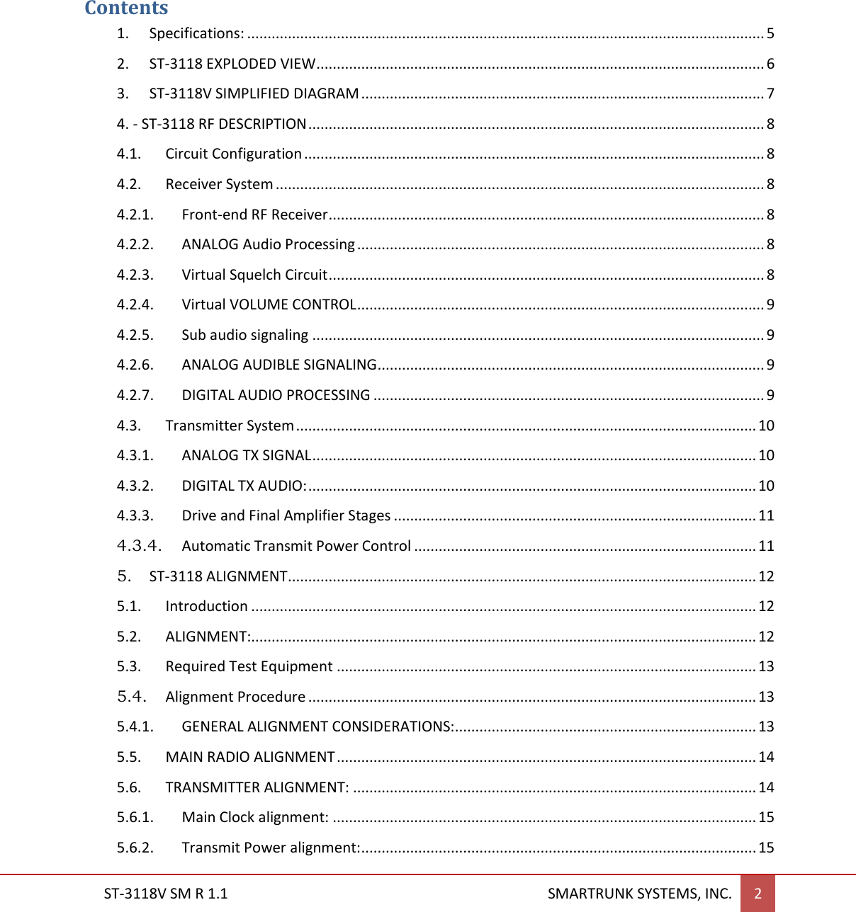
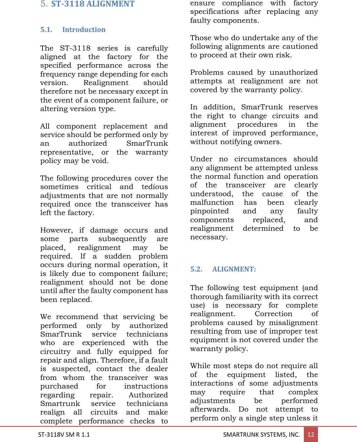
![ST-3118V SM R 1.1 SMARTRUNK SYSTEMS, INC. 10 and fed it to the audio power amplifier (U8). 4.3. Transmitter System 4.3.1. ANALOG TX SIGNAL The Mic signal coming from the front connector, the external Mic signal coming from the accessory connector or the output of the PWM filter and fed into an analog selector/switch (U5), then fed into the microphone pre-amplifier (U7). The result of the conditioned and in band-filtered signal is fed to the Audio Processor (U12), which provides audio compander, emphasize, limitation, encryption, etc. The high audio band of the signal from 300 to 3500 Hz are directly fed to the transmitter (U2), which performs a direct modulation of a generated carrier. Low frequency signaling audio are fed directly to Y1 VC TXCO main clock generator and U2 with a corresponding balance controlled by software. 4.3.2. DIGITAL TX AUDIO: The Mic signal coming from the front connector, the external Mic signal coming from the accessory connector or the output of the PWM filter and fed into an analog selector/switch (U5), then fed into the microphone pre-amplifier (U7). After conditioning and band limiting, the signal is fed directly to the vocoder chip (U14) which perform the data codification, delivering the digitized and encoded audio as digital frames, which are processed by the Main Processor (U13), which add a FEC (Frame Error Correction), encrypt the information and add the user related information as user ID, etc. The final data frame is fed to the Audio Processor (U12), which has a built in modem, which operates for FDMA or TDMA signals, controlling the modulation of the Transmitter (U2) through the VC TXCO for DC to low frequencies and the direct modulation for higher frequencies. AMPLIFIER [U7] AUDIO PROCESSOR [U12] TRANSMITTER [U2] VC TXCO [Y1] Mic Selector [U5] Mic External PW Internal External AUDIO PROCESSOR TRANSMITTER [U2] VC TXCO [Y1] MAIN PROCESSOR [U13] VOCODER [u14] AMPLIFIER Mic Selector [U5] Mic PW Figure 4: Digital Modulation path Figure 5: Analog Modulation path](https://usermanual.wiki/Ranger-Communications/ST-3118V/User-Guide-2891402-Page-8.png)
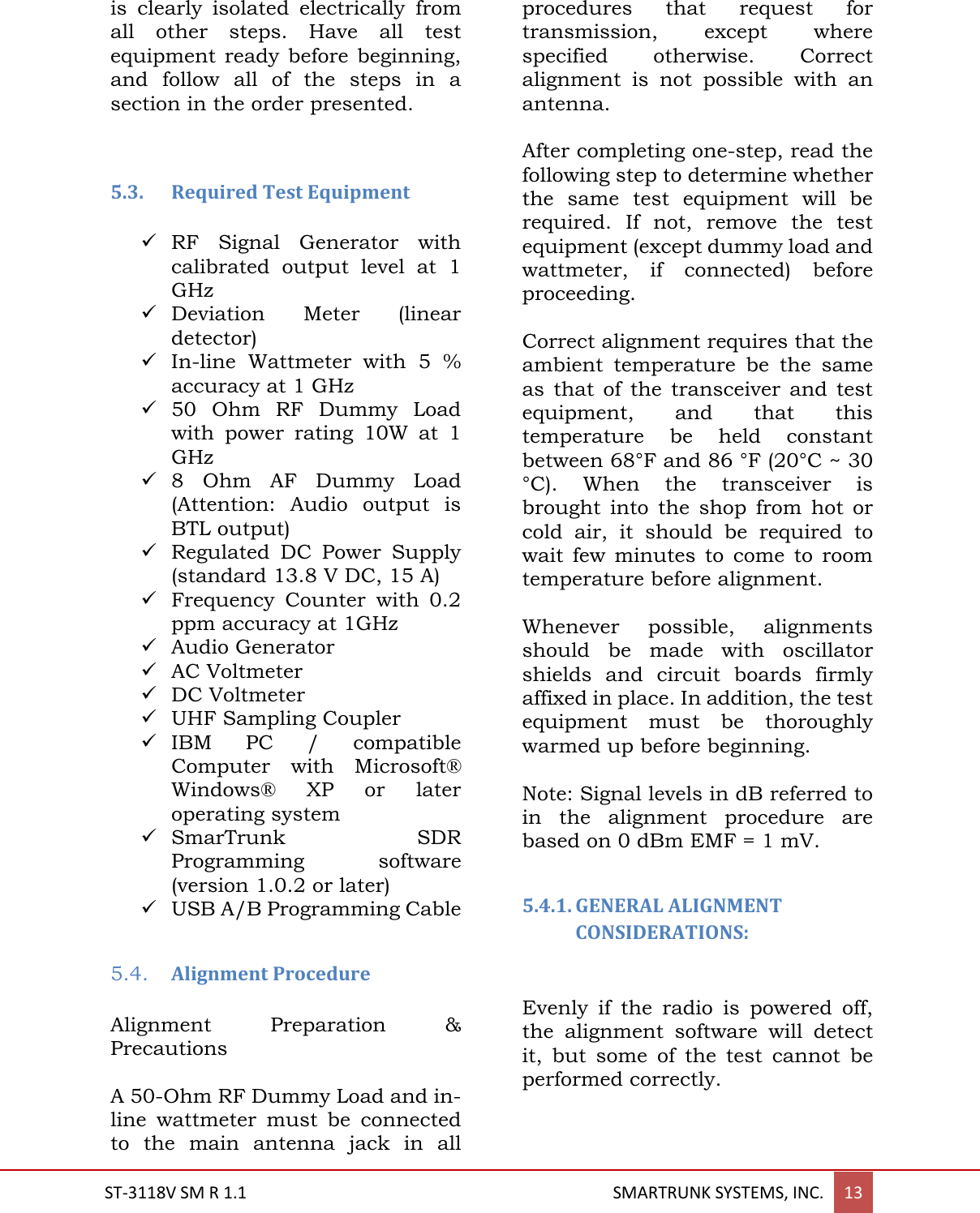
![ST-3118V SM R 1.1 SMARTRUNK SYSTEMS, INC. 11 4.3.3. Drive and Final Amplifier Stages Final RF is amplified on Q1 (2SC5226) adjusting the impedance, then filtered to be fed to Q2 (2SC3357) then finally amplified by U3 (RA60H1317) up to 50 watts output power. The transmit signal then passes through Forward and reflected power bridge (U1), then to the antenna switch D1/D2 (UM9401F) and is low-pass filtered to suppress harmonic spurious radiation before delivery to the antenna. 4.3.4. Automatic Transmit Power Control The RF power detector (U1) detects transmitted feedback and reverse power feedback, then the detected signals are send to power control stage (U10) to be compared with the referenced power control coming from audio processor U12 (CMX-7141). The reference power level are set my the main processor (U13) to the audio processor (U12) in agree to the current channel information stored into the memory. Power control stage (U10) also compares the reverse power feedback coming from power meter bridge (U1) to protect the power module in case of antenna mismatching. The output of the power control stage (U10) is fed direct to the RF power Amplifier (U3) controlling the DC bias import for the hybrid module. Evenly when power level is adjusted by software on three levels (Hi, Med, Lo) the power value can be adjusted to any desired value between zero and 50Watts by the alignment software. LPF Ant Sw D1/D2/ D6 Final AMP U3 Power Detection U1 Driver Q2 Buffer AMP Q1 TX CTRL [Q9 Q18] POWER CTRL [U10] Figure 6: RF transmission path](https://usermanual.wiki/Ranger-Communications/ST-3118V/User-Guide-2891402-Page-9.png)
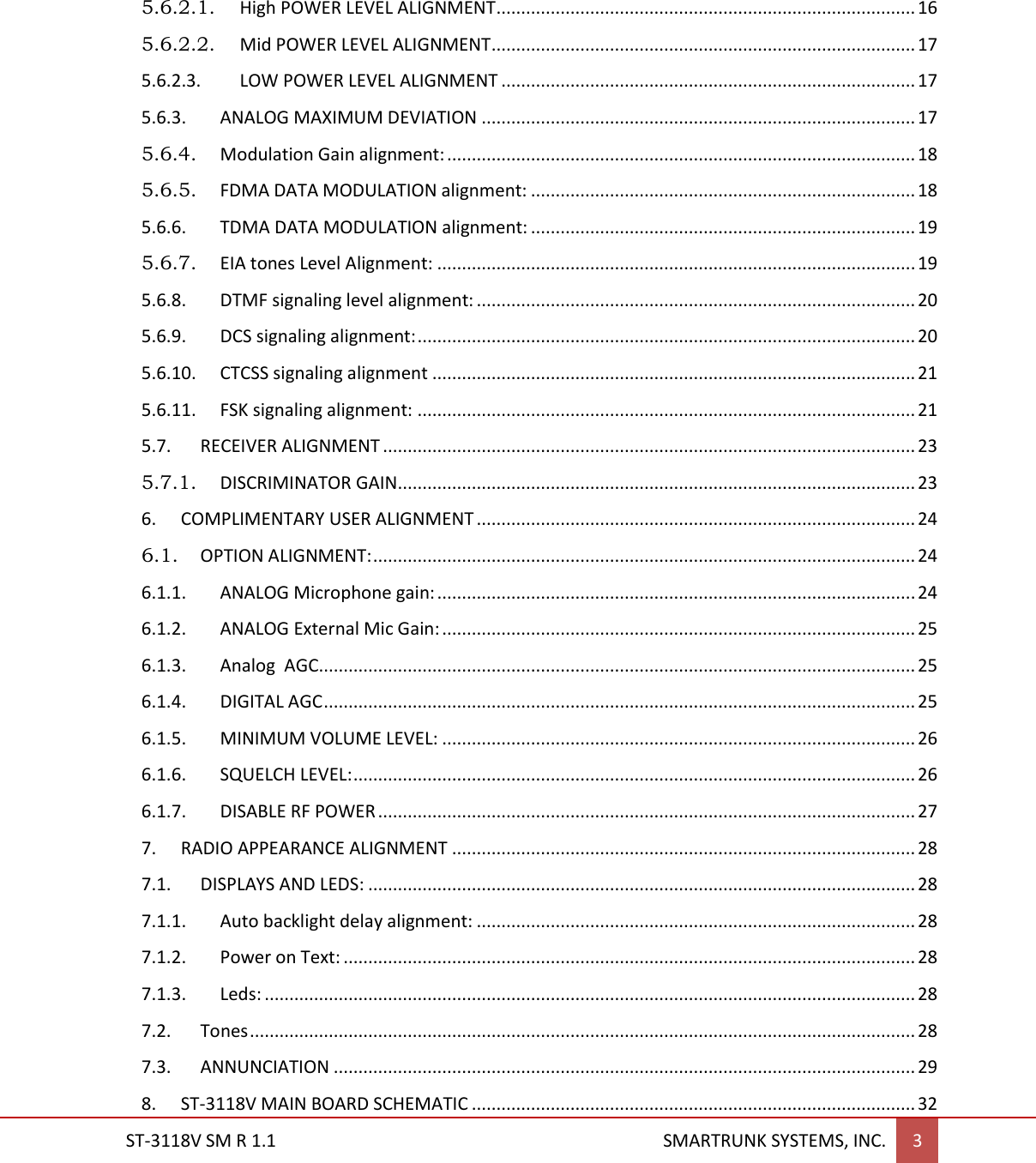
![ST-3118V SM R 1.1 SMARTRUNK SYSTEMS, INC. 15 Setup the test equipment as shown for transceiver alignment, apply 13.8V DC power to the transceiver. The RF parameters are typed on the alignment software to facilitate the alignment within all radio band avoiding special programming of the radio before start alignment procedure. All parameters can be aligned without relationship to any other, so there is no an order to align. On this way, you can adjust only the desired parameter, avoiding to waste time realigning other parameters than required. Before proceed to align any parameter, a desired frequency must be loaded into both TX and RX. Evenly when the radio has stable characteristics for all bandwidth, it is recommendable to align on middle of the radio-working band. 5.6.1. Main Clock alignment: To align the main clock for radio Tx and RX, please select: Main Clock Adjust option Alignment screen. Figure 10: Main Clock Alignment Actual alignment value will be displayed on alignment slider. Press [Start] then move the slider to reach the desired value at the time you checks the Frequency Counter to reach the desired frequency as shown on Frequency field of the alignment screen. As soon the desired value is reached, press [Finish] to store the value on radio memory. Typical default alignment correspond to a max error of 60Hz on the alignment clock in factory when the radio was calibrated. If you want to retrieve factory default, press [Factory] instead of [Start]. You will be asked to confirm the factory default alignment, and then, if you confirm it, original values from factory will be loaded into current alignment settings. This confirmation screen will appears any time you want to realign any parameter to Factory Default. 5.6.2. Transmit Power alignment: ST-3118 has three power levels to be selected for each channel. High, medium and low power level can be aligned as per radio usage requirement. Figure 11: Default Alignment Values Retrieve](https://usermanual.wiki/Ranger-Communications/ST-3118V/User-Guide-2891402-Page-13.png)
![ST-3118V SM R 1.1 SMARTRUNK SYSTEMS, INC. 16 For power alignment, you can do a fine-tuning as per your desire frequency sub-band. The software lets you linearize the complete band dividing the complete band into five steps to let you focus into your frequency bands. Even when the software has already assigned the most convenient frequency points to consider the alignment, you still can enter exactly the frequency of your interest. 5.6.2.1. High POWER LEVEL ALIGNMENT To align the High Power level select Power High Level. Software automatically retrieves actual level to the alignment slider. Figure 12: Power High Level Alignment This level has been aligned in factory, but you still can adjust is as per your desires. To realign, please select [Start] then move the slider or introduce the value manually at the time you check the real transmit power on the wattmeter connected to the radio as recommended on TX alignment diagram. As soon as [Start] is pressed, the radio start to transmit a carrier, so please verify the antenna dummy load is properly connected to avoid any damage to the transmitter. As soon the desired value is reached, press [Finish] to store the value into radio memory. If you want to load default High power only, keeping any other value without any change, press [Factory] instead of [Start]. A pop up window will ask you to confirm the default parameters upload to the radio power. Press [OK] to confirm. As descripted previously, you can manually select the frequency range to align, divided into five different sub-ranges. You can also define the right frequency of interest to align, typing the desired one into the frequency field: If selected frequency is not supported by radio hardware, the frequency field will be filled on red. In case the PLL is locked, then it becomes filled on green. Please be sure that the PLL is locked as soon as you press [Start], otherwise the alignment should be not correct.](https://usermanual.wiki/Ranger-Communications/ST-3118V/User-Guide-2891402-Page-14.png)
![ST-3118V SM R 1.1 SMARTRUNK SYSTEMS, INC. 17 5.6.2.2. Mid POWER LEVEL ALIGNMENT Repeat the same procedure to align High Power, but select Power Medium Level on the alignment menu. Figure 13: Medium Power Level Alignment 5.6.2.3. LOW POWER LEVEL ALIGNMENT Repeat the same procedure to align High Power, but select Power Low Level on the alignment menu. 5.6.3. ANALOG MAXIMUM DEVIATION Maximum deviation for analog signals modulated from ST-3118 can be aligned by Max Deviation alignment option form the alignment menu. Figure 15: Analog Max Deviation Alignment Actual alignment value will be displayed on alignment slider. Press [Start] then move the slider to reach the desired value at the time you checks the deviation meter to reach the desired signaling level for narrow band operation. Radio will generate a 1000Hz alignment reference tone for alignment proposes. As soon the desired value is reached, press [Finish] to store the value on radio memory. Default value has been set to a right value, which correspond to 2.5 KHz Max deviation for Narrowband channels (12.5Khz channel bandwidth). If you want to retrieve factory default, press [Factory] instead of [Start]. You will be asked to confirm the factory default alignment, and then if you confirm it, original values from factory will be loaded into current alignment settings Figure 14: Low Power Level Alignment](https://usermanual.wiki/Ranger-Communications/ST-3118V/User-Guide-2891402-Page-15.png)
![ST-3118V SM R 1.1 SMARTRUNK SYSTEMS, INC. 18 5.6.4. Modulation Gain alignment: This is a critical parameter, which may not be realigned to different values other than factory default. Lower gain means a very high microphone gain must be assigned to get the proper radio voice deviation, and higher gain means a risk because the max deviation limit must be reached by any signal, which makes the limiter to introduce distortion to avoid over deviation. Under your risk, if you still prefer to realign the overall modulation gain, you must select Modulator Gain on Alignment screen. Figure 17: Modulator Gain Alignment Actual alignment value will be displayed on alignment slider. Press [Start] then move the slider to reach the desired value at the time you checks the deviation meter to reach the desired signaling level for narrow band operation. For this alignment step, the radio does not generate any signal. It only stores the new value of the overall modulation gain into the memory. As soon the desired value is reached, press [Finish] to store the value on radio memory. If you want to retrieve factory default, press [Factory] instead of [Start]. You will be asked to confirm the factory default alignment, and then, if you confirm it, original values from factory will be loaded into current alignment settings. 5.6.5. FDMA DATA MODULATION alignment: To align 4FSK signaling deviation for FDMA mode, select FDMA Deviation on Alignment screen. Actual alignment value will be displayed on alignment slider. Press [Start] then move the slider to reach the desired value at the time you checks the deviation meter to reach the desired signaling level for narrow band operation. Radio will generate a 1000Hz alignment reference tone for alignment proposes. Figure 16: FDMA Deviation Alignment](https://usermanual.wiki/Ranger-Communications/ST-3118V/User-Guide-2891402-Page-16.png)
![ST-3118V SM R 1.1 SMARTRUNK SYSTEMS, INC. 19 As soon the desired value is reached, press [Finish] to store the value on radio memory. If you want to retrieve factory default, press [Factory] instead of [Start]. You will be asked to confirm the factory default alignment, and then if you confirm it, original values from factory will be loaded into current alignment settings. 5.6.6. TDMA DATA MODULATION alignment: To align 4FSK signaling deviation for TDMA mode (12.5Khz channel bandwidth), select TDMA Deviation on Alignment screen. Figure 18:TDMA Deviation Alignment Actual alignment value will be displayed on alignment slider. Press [Start] then move the slider to reach the desired value at the time you checks the deviation meter to reach the desired signaling level for narrow band operation. Radio will generate a 1000Hz alignment reference tone for alignment proposes. As soon the desired value is reached, press [Finish] to store the value on radio memory. Default value corresponds to 2.2 KHz deviation for Narrowband channels (12.5Khz channel bandwidth). If you want to retrieve factory default, press [Factory] instead of [Start]. You will be asked to confirm the factory default alignment, and then if you confirm it, original values from factory will be loaded into current alignment settings. 5.6.7. EIA tones Level Alignment: EIA signaling generated by ST-3118 must be aligned by selecting EIA Tones Level alignment option form the alignment menu. Actual alignment value will be displayed on alignment slider. Press [Start] then move the slider to reach the desired value at the time you checks the deviation meter to reach the desired signaling level for narrow band operation. Radio will generate a 1000Hz alignment Figure 19: EIA Tones Level Alignment Screen](https://usermanual.wiki/Ranger-Communications/ST-3118V/User-Guide-2891402-Page-17.png)
![ST-3118V SM R 1.1 SMARTRUNK SYSTEMS, INC. 20 reference tone for alignment proposes. As soon the desired value is reached, press [Finish] to store the value on radio memory. Default value correspond to 1.8Khz deviation for narrow band channels. If you want to retrieve factory default, press [Factory] instead of [Start]. You will be asked to confirm the factory default alignment, and then if you confirm it, original values from factory will be loaded into current alignment settings. 5.6.8. DTMF signaling level alignment: DTMF signaling generated by ST-3118 must be aligned by selecting DTMF Level alignment option form the alignment menu. Actual alignment value will be displayed on alignment slider. Press [Start] then move the slider to reach the desired value at the time you checks the deviation meter to reach the desired signaling level for narrow band operation. Radio will generate a 1000Hz alignment reference tone for alignment proposes. As soon the desired value is reached, press [Finish] to store the value on radio memory. Default value corresponds to 1.8Khz deviation for Narrow band channels. If you want to retrieve factory default, press [Factory] instead of [Start]. You will be asked to confirm the factory default alignment, and then if you confirm it, original values from factory will be loaded into current alignment settings. 5.6.9. DCS signaling alignment: DCS signaling encoded from ST-3118 must be aligned by selecting DCS Level alignment option form the alignment menu. Actual alignment value will be displayed on alignment slider. Figure 20: DTMF Level Alignment Screen Figure 21DCS Level Alignment Screen](https://usermanual.wiki/Ranger-Communications/ST-3118V/User-Guide-2891402-Page-18.png)
![ST-3118V SM R 1.1 SMARTRUNK SYSTEMS, INC. 21 Press Start then move the slider to reach the desired value at the time you checks the deviation meter to reach the desired signaling level for narrow band operation. Radio will generate 134.4Hz audio tone for alignment proposes. As soon the desired value is reached, press [Finish] to store the value on radio memory. Default value corresponds to 300Hz deviation for narrow band channels. If you want to retrieve factory default, press [Factory] instead of [Start]. You will be asked to confirm the factory default alignment, and then if you confirm it, original values from factory will be loaded into current alignment settings. 5.6.10. CTCSS signaling alignment CTCSS signaling encoded from ST-3118 can be aligned by selecting CTCSS Level alignment option form the alignment menu. Actual alignment value will be displayed on alignment slider. Press [Start] then move the slider to reach the desired value at the time you checks the deviation meter to reach the desired signaling level for narrow band operation. Radio will generate 123.0Hz audio tone for alignment proposes. As soon the desired value is reached, press [Finish] to store the value on radio memory. Default value corresponds to 300Hz deviation for narrow band channels. If you want to retrieve factory default, press [Factory] instead of [Start]. You will be asked to confirm the factory default alignment, and then if you confirm it, original values from factory will be loaded into current alignment settings. 5.6.11. FSK signaling alignment: To align FSK/PSK signaling deviation, select FSK Mod Level on Alignment screen. Figure 23: FSK Modulation Level Alignment Screen Actual alignment value will be displayed on alignment slider. Figure 22: CTCSS Level Alignment Screen](https://usermanual.wiki/Ranger-Communications/ST-3118V/User-Guide-2891402-Page-19.png)
![ST-3118V SM R 1.1 SMARTRUNK SYSTEMS, INC. 22 Press [Start] then move the slider to reach the desired value at the time you checks the deviation meter to reach the desired signaling level for narrow band operation. Radio will generate a 1000Hz alignment reference tone for alignment proposes. As soon the desired value is reached, press [Finish] to store the value on radio memory. Default value corresponds to 1.8 KHz deviation for narrow band channels (12.5Khz channel bandwidth). If you want to retrieve factory default, press [Factory] instead of [Start]. You will be asked to confirm the factory default alignment, and then if you confirm it, original values from factory will be loaded into current alignment settings.](https://usermanual.wiki/Ranger-Communications/ST-3118V/User-Guide-2891402-Page-20.png)
![ST-3118V SM R 1.1 SMARTRUNK SYSTEMS, INC. 23 5.7. RECEIVER ALIGNMENT Setup the test equipment as shown for Receiver alignment, apply 13.8 V DC power to the transceiver. The RF frequency must be loaded on Receiver Frequency of the alignment software to facilitate the alignment within all radio band avoiding special programming of the radio before start alignment procedure. 7.5V Power SupplyPC compatibleRF signal generator Figure 24: Receiver Alignment Setup 5.7.1. DISCRIMINATOR GAIN This is a critical parameter, which may not be realigned to different values other than factory default. Under your risk, if you still prefer to realign the overall modulation gain, you must select Discriminator Gain on Alignment screen. Figure 25: Discriminator Gain Alignment Screen Actual alignment value will be displayed on alignment slider. Press [Start] then move the slider to reach the desired value at the time you checks the deviation meter to reach the desired signaling level for narrow band operation. As soon the desired value is reached, press [Finish] to store the value on radio memory. If you want to retrieve factory default, press [Factory] instead of [Start]. You will be asked to confirm the factory default alignment, and then if you confirm it, original values from factory will be loaded into current alignment settings. 13.8Vdc Power Supply](https://usermanual.wiki/Ranger-Communications/ST-3118V/User-Guide-2891402-Page-21.png)
![ST-3118V SM R 1.1 SMARTRUNK SYSTEMS, INC. 24 6. COMPLIMENTARY USER ALIGNMENT The above parameters only can be aligned under dealer login and most of them should be critical for proper radio performance. Additional complimentary parameters should be also aligned on user login mode; it means the user can align it as per the most convenient way for particular radio usage. 6.1. OPTION ALIGNMENT: To access to the option alignment menu, select Edit then Option form the main software toolbar: Figure 26: Optional Alignment Access As soon as you click on Options… the Options screen is popped up: Figure 27: Option Alignment Screen From this screen the user can adjust: 6.1.1. ANALOG Microphone gain: It aligns microphone sensitivity. Figure 28: Analog Mic Gain Selection Alignment step is 3.2dB. For noisy environments, or when voice encryption is used, we recommend keeping it as low as possible. Press [OK] to store it in the file. The value will be updated after the file is transferred to the radio.](https://usermanual.wiki/Ranger-Communications/ST-3118V/User-Guide-2891402-Page-22.png)
![ST-3118V SM R 1.1 SMARTRUNK SYSTEMS, INC. 25 6.1.2. ANALOG External Mic Gain: It aligns external microphone Accessory Port) sensitivity. Default factory value is 0.0dB. Figure 29: External Microphone Sensitivity Alignment Alignment step is 3.2dB. For noisy environments or when voice encryption is used, we recommend keeping it as low as possible. Press [OK] to store it in the file. The value will be updated after the file is transferred to the radio. 6.1.3. Analog AGC ST-3118 has an Automated Gain Control for analog microphone. This function adjusts the gain to reach a dynamic gain value, which makes the analog voice deviation be equivalent to the right deviation produced by 50mV RMS on the microphone output, and the selected target gain. If you want to use AGC, then you must select the target equivalent gain on the Mic Gain then check the ACG Check Box. For example, if you want a dynamic gain which causes the same effect that a gain of 6.4dB when the voice on the microphone causes 50mV RMS in the microphone switch output (standard voice at 4 inches away from the microphone), or 0dB gain on the external microphone connection, then you must program the Analog Gain at 6.4dB and check AGC as bellow: Figure 30: Analog Microphone AGC Control Press [OK] to store it in the file. The value will be updated after the file is transferred to the radio. 6.1.4. DIGITAL AGC ST-3118 has an Automated Gain Control for digital microphone path. This function adjusts the gain to reach a dynamic gain value, which makes the voice to be equivalent to the right voice digitally played back in the other end, produced by 50mV RMS on the microphone output, and the selected target gain. If you want to use AGC, then you must select the target equivalent](https://usermanual.wiki/Ranger-Communications/ST-3118V/User-Guide-2891402-Page-23.png)
![ST-3118V SM R 1.1 SMARTRUNK SYSTEMS, INC. 26 gain on the Mic Gain then check the Digital ACG Check Box. For example, if you want a dynamic gain which causes the same effect that a gain of 15.0dB when the voice on the microphone causes 50mV RMS in the microphone switch output (standard voice at 4 inches away from the microphone), or 6.0dB gain on the external microphone connection, then you must program the Digital Gain at 15.0dB and the external gain on 6.0dB, then check Digital AGC as bellow: Figure 31: Digital Microphone Path AGC Control Press [OK] to store it in the file. The value will be updated after the file is transferred to the radio. 6.1.5. MINIMUM VOLUME LEVEL: This alignment lets the user to ensure the speaker level should be audible, evenly when the volume control potentiometer is fully closed counter clockwise. It can be aligned up to 250 (max) step 1. 6.1.6. SQUELCH LEVEL: ST-3118 supports individual squelch alignment for any channel to be programmed individually on each frequency defined into the frequency chart of each bank. On this way, the user can set a higher threshold level for noisy channels and lower for clear channels. Once programmed, if due to the proximity of the radio to a noisy environment the squelch level is not high enough, the user can adjust a common reference for all the channels in the radio by adjusting the general squelch level. Option screen on the edit menu, lets you to program the default squelch reference for all the channels. This value can be adjusted on the fly for the user if the dealer program on squelch control key or navigating through the radio menu. To set a desired squelch reference, please select you desired squelch level form the list: Figure 32: Squelch Level Setting Screen Press [OK] to store it in the file. The value will be updated after the file is transferred to the radio.](https://usermanual.wiki/Ranger-Communications/ST-3118V/User-Guide-2891402-Page-24.png)
![ST-3118V SM R 1.1 SMARTRUNK SYSTEMS, INC. 27 6.1.7. DISABLE RF POWER Use this box to check when you do not want to use the RF power amplifier. It is commonly used for dealers to make a demonstration of the radio features without interfering to any other existing user in the frequency or for operation without antenna connected to the radio. To disable the RF power amplifier, check the box: Press [OK] to store it in the file. The value will be updated after the file is transferred to the radio.](https://usermanual.wiki/Ranger-Communications/ST-3118V/User-Guide-2891402-Page-25.png)