Ranger Communications ST-9116D Repeater User Manual rev
Ranger Communications (M) SDN. BHD. Repeater rev
UserManual.wiki
>
Ranger Communications
>
ST 9116D User Manual
user manual rev
Navigation menu
Upload a User Manual
Namespaces
Wiki Guide
HTML
PDF
Info
Views
User Manual
Discussion / Help
Navigation
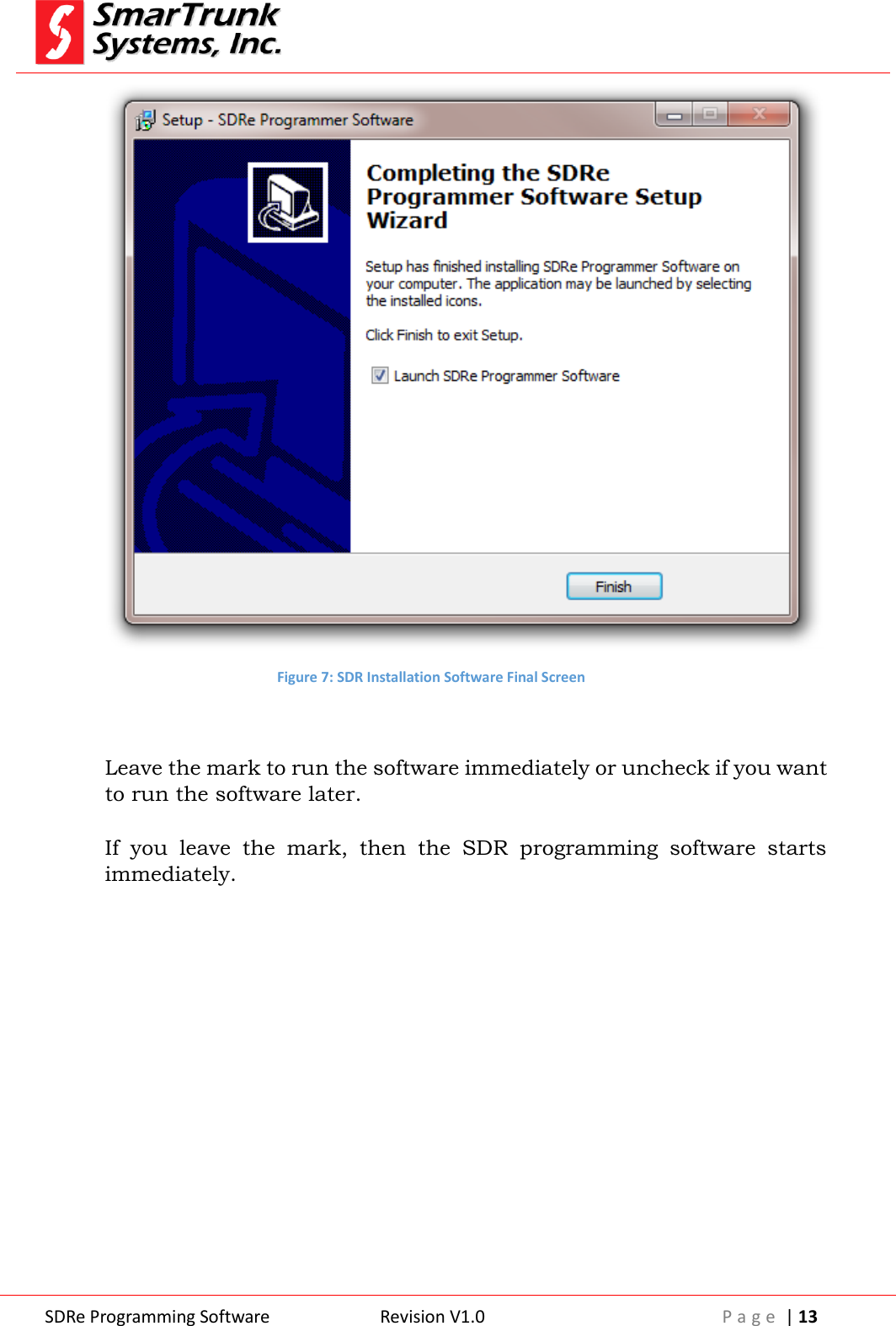
![SDRe Programming Software Revision V1.0 P a g e | 7 Figure 1: SDR programming software welcome screen Click on [Next] to start the installation process. You will be prompted to introduce the destination folder. By default it is: C:\Program Files (x86)\Smartrunk\SDRe_Programmer However, you can change it as per your convenience.](https://usermanual.wiki/Ranger-Communications/ST-9116D/User-Guide-2837370-Page-7.png)
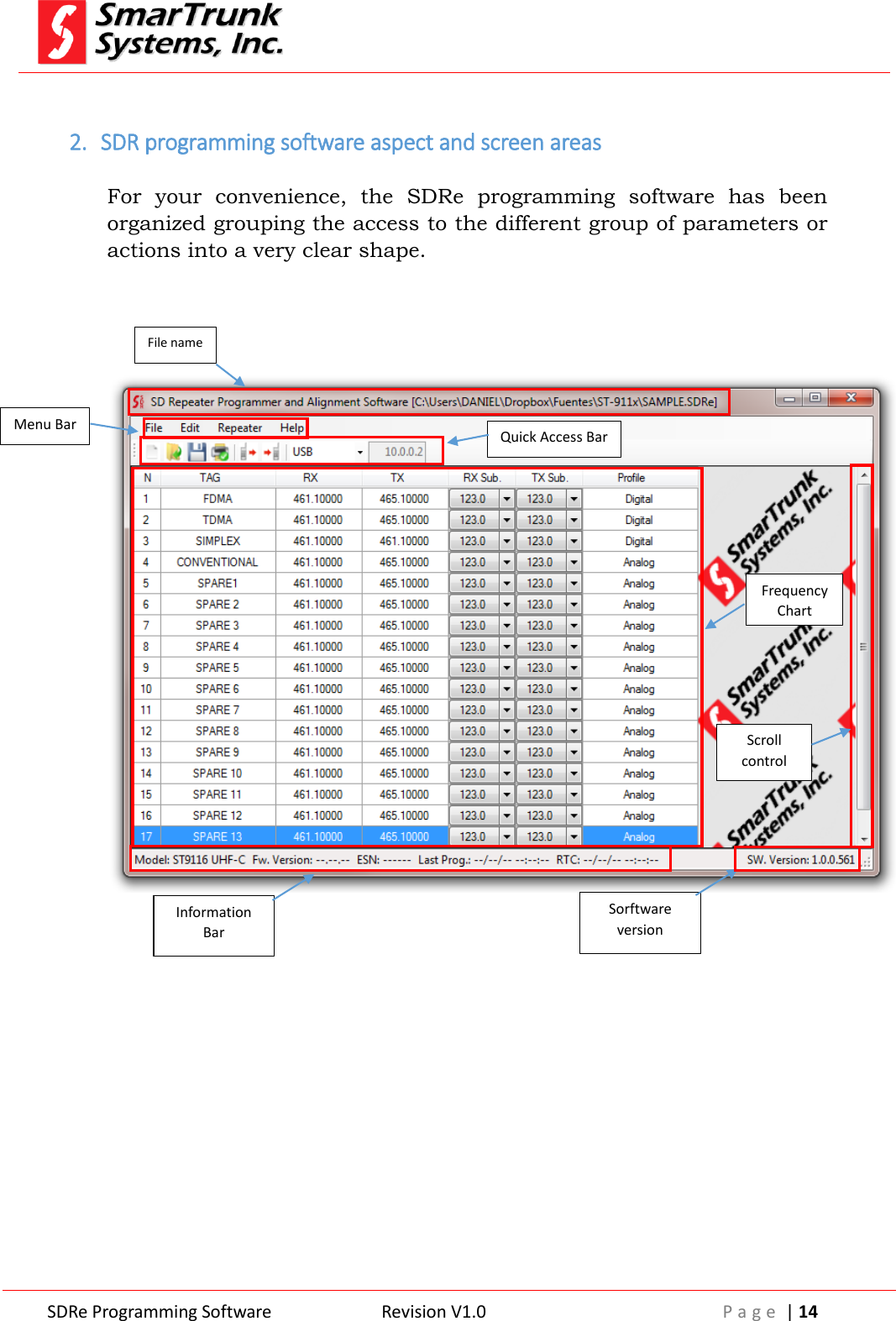
![SDRe Programming Software Revision V1.0 P a g e | 8 Figure 2: SDR programming software file location setup Click on [Next] to continue or [Back] to return to previous step. Please be sure that you have, at least, minimum free space in your destination disk as per the recommended on this screen Note: 2 Disk space requirement](https://usermanual.wiki/Ranger-Communications/ST-9116D/User-Guide-2837370-Page-8.png)
![SDRe Programming Software Revision V1.0 P a g e | 9 Figure 3: Start Menu destination Please type the desired Menu folder where you will find the shortcut to run the software once installed into your computer. Default name is: SDRe Programmer Software Click on [Next] to continue or [Back] to return to the previous step.](https://usermanual.wiki/Ranger-Communications/ST-9116D/User-Guide-2837370-Page-9.png)
![SDRe Programming Software Revision V1.0 P a g e | 10 Figure 4: Additional task to be performed by installation software If you do not want to create a shortcut into desktop, then uncheck the mark. Click on [Next] to continue or [Back] to return to the previous step.](https://usermanual.wiki/Ranger-Communications/ST-9116D/User-Guide-2837370-Page-10.png)
![SDRe Programming Software Revision V1.0 P a g e | 11 Figure 5: Installation parameters review Check the option listed to ensure it is in agree to your desired setting, then press [Install] to proceed with the installation or press [Back] to return to the previous step As soon as you press install, the progress bar shows you the installation process evolution. It will take only few seconds to perform.](https://usermanual.wiki/Ranger-Communications/ST-9116D/User-Guide-2837370-Page-11.png)
![SDRe Programming Software Revision V1.0 P a g e | 18 As soon as you click on [Configuration], the right configuration screen pops up. Figure 10: SDRe Programming Software Configuration Screen 2.2.1. Repeater link to the computer: You can choose to connect your radios to the computer by USB (default) or TCP/IP media protocol. In case of USB media connection to the radio, it should be required to install the drivers for your USB device. As soon as you plug a SDR repeater to the computer through the USB port, you will be prompted to install the driver. Installation software already copy the files into the selected directory you have introduced into the installation time, under {Drivers} folder: For example: C:\Program Files (x86)\SmarTrunk\SDRe_Programmer\Driver Once you complete driver installation, the connection to the repeater will be done automatically. The drivers must be installed only once. As SDR repeater is not a standard device included into MW Windows library, you must install the drivers before read or write a radio. Note: 3 - Driver installation alert for USB Media Connection](https://usermanual.wiki/Ranger-Communications/ST-9116D/User-Guide-2837370-Page-18.png)
![SDRe Programming Software Revision V1.0 P a g e | 20 3. File operations: 3.1. New program file creation: Evenly when in the future you can use existing files as templates to define the programming file of a repeater, the first time you must start from scratch, cleaning the dashboard. To create a new file you can use the quick access bar then click on the new file shortcut or goes through [File] menu, and then select [New] Figure 14: New file access through File menu 3.2. Open an existing template or file To open an existing file or a template, please proceed to click on [File] then [Open].](https://usermanual.wiki/Ranger-Communications/ST-9116D/User-Guide-2837370-Page-20.png)
![SDRe Programming Software Revision V1.0 P a g e | 21 Figure 15: Accessing to open an existing file or template As soon as you clock on [Open] a windows Explorer screen will help you to find the file. You can also use the shortcut from the quick bar . Once you found the file, click on [Open] to load the information into your programming software dashboard. 3.3. Saving the dashboard information to the currently opened file. To save current information on the programming software dashboard, you can press [File] then [Save]. The currently opened file will be updated. Alternatively, you can also use the icon in the quick access bar: 3.4. Saving current dashboard into different file To save current information on the programming software dashboard but in different file, you can press [File] then [Save As]. A typical windows Explorer screen will prompt you to input the desired file name and find the file location. Once selected it, the information will be saved into the file. In case the selected file name exists, the software will alert you to before overwrite it.](https://usermanual.wiki/Ranger-Communications/ST-9116D/User-Guide-2837370-Page-21.png)
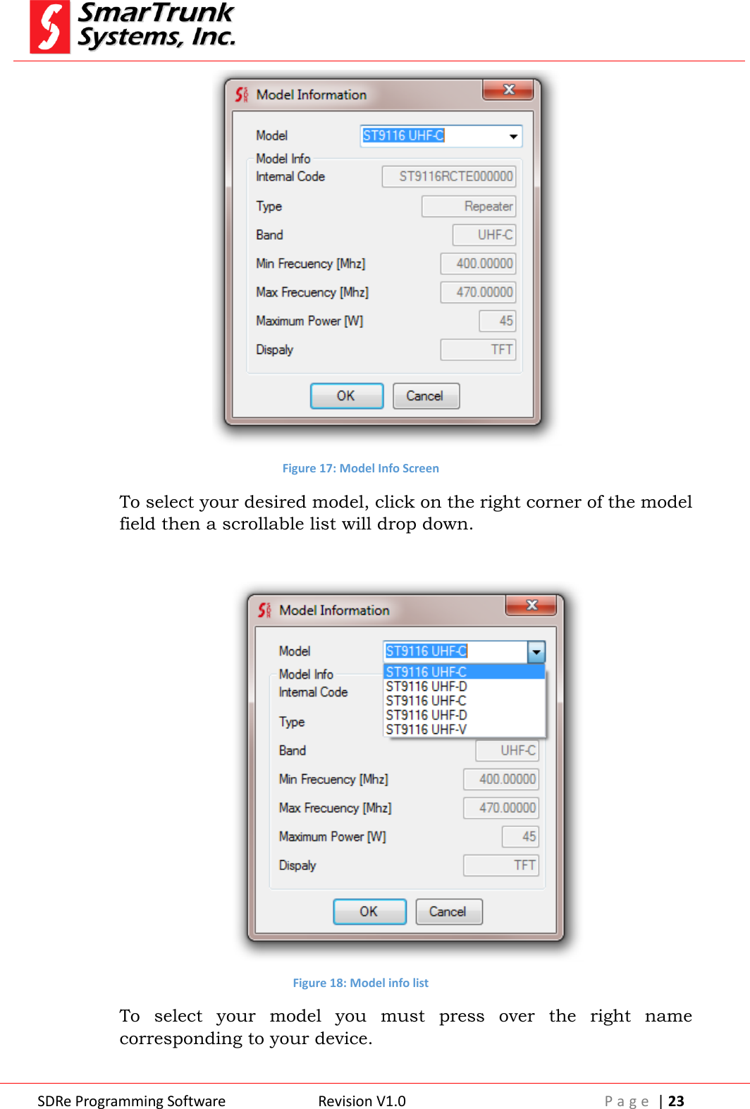
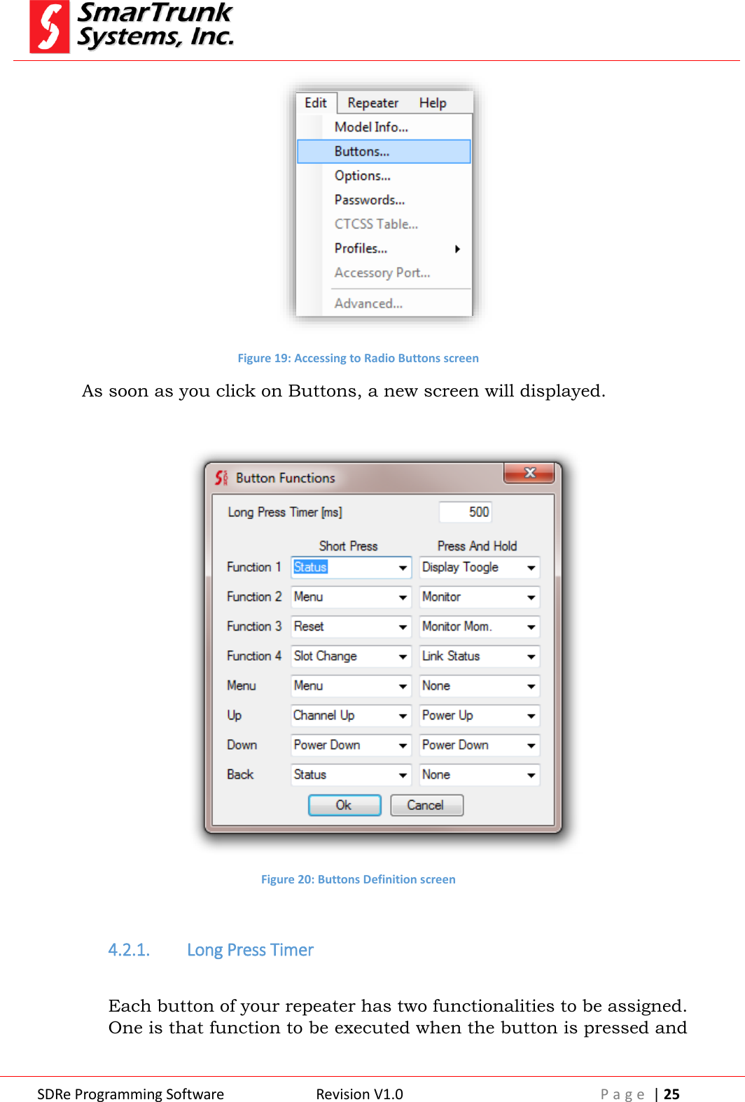
![SDRe Programming Software Revision V1.0 P a g e | 24 If your repeater model is not in your list, please update your software. If you are not sure about your model info, you can read the repeater by pressing the read button on the quick access bar once your repeater is connected through the Ethernet port or USB cable with the computer where the SDRe programming software is running. Model info is also into the serial number label in the backside of your repeater. Once the model is selected, the correct frequency range, max power and accessories are enabled into the model info screen. Model: is the general model of the radio family. Internal Code: is a production code assigned to the repeater into the manufacturing process. Radio Type: is the type of device. Min Freq: Refer to the lowest operational frequency, which can be programmed into your repeater. Max Freq: Refer to the lowest operational frequency, which can be programmed into your repeater. Maximum Power: Is the maximum power supported by your RF TX configuration. It may be different, depending on the region. Display: Shows the type of display of the repeater Once selected the right model press [OK] to accept it. 4.2. Repeater Buttons Definition Before using the repeater, you must assign the functionality of each one of the repeater buttons. Please click on [Edit] then [Buttons] to access to the buttons definition screen. It is important to keep your software updated to ensure any SDRe repeater is into the model info list. If your model is not into the current list, please update your repeater Note: 5 - Incomplete model info list requires software update](https://usermanual.wiki/Ranger-Communications/ST-9116D/User-Guide-2837370-Page-24.png)
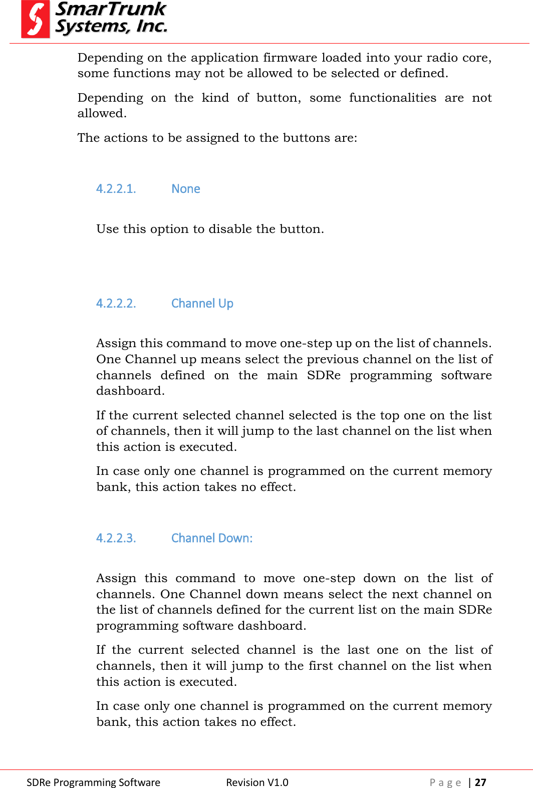
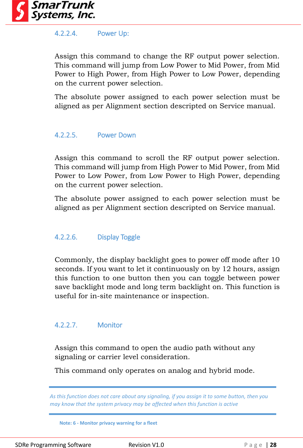
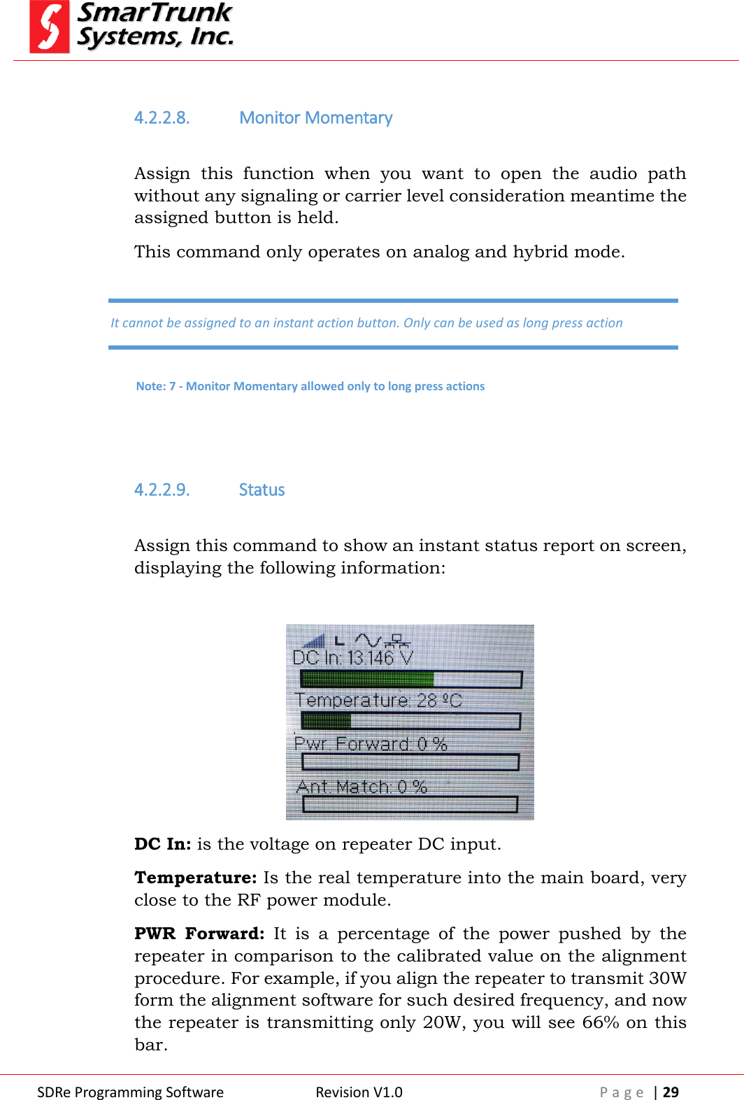
![SDRe Programming Software Revision V1.0 P a g e | 26 released immediately and the other is that function to be executed when the button is pressed by long time. Long Press timer is the minimum time in milliseconds [ms] that a key must be held to be considered as Press and Hold action. This parameter can be adjusted form 100msec up to 2500 msec. Please define it as per your convenience. 4.2.2. Buttons Actions: The Buttons Definition Screen lets you to assign different functions to repeater buttons. Click on the side arrow to open the selection list of possible functions to be assigned to any of the buttons, and then click on the desired function to be assigned. Figure 21: Assigning the function to a button To finish the function assignment, press [Ok] to return to the main dashboard. Press And Hold means a long push function assigned to such button.](https://usermanual.wiki/Ranger-Communications/ST-9116D/User-Guide-2837370-Page-26.png)

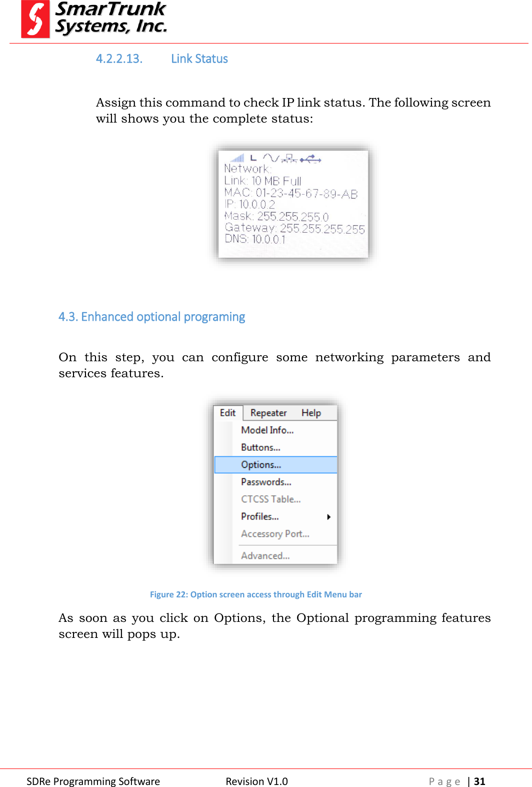
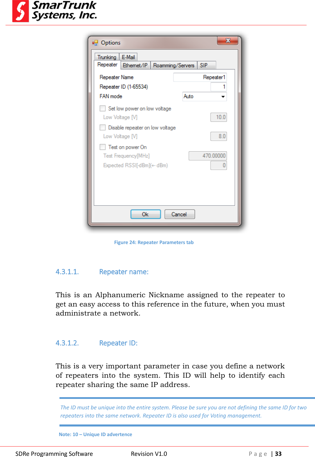
![SDRe Programming Software Revision V1.0 P a g e | 32 Figure 23: Options Program screen To save the setting press [Ok] or [Cancel] to exit without saving the data changes 4.3.1. Repeater parameters This area lest you set some parameters:](https://usermanual.wiki/Ranger-Communications/ST-9116D/User-Guide-2837370-Page-32.png)
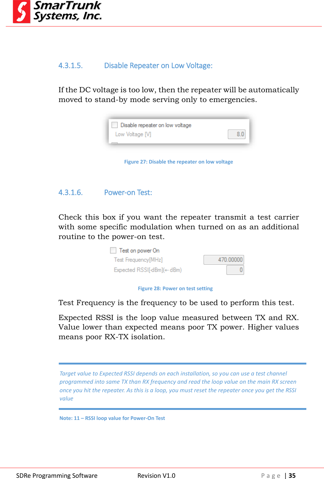
![SDRe Programming Software Revision V1.0 P a g e | 34 4.3.1.3. FAN Mode: The operating temperature of the repeater may not exceed 100°C [212°F]. Depending on environmental conditions, the internal FAN will help the heat-sync to keep temperature under the limit, extending the repeater performance. Press on the arrow to list down the possible values: Figure 25: FAN Setting Auto: The FAN will work controlled by repeater temperature limits programed on the alignment procedure (See ST-9116 Service manual – Alignment). On: The FAN will remains all time on. This option will demand more quiescent current than required becoming inefficient. It should be useful for high temperature environments. Off: The FAN never will blow. 4.3.1.4. Set Low Power on Voltage: If the DC power voltage drops under the limit programmed on this field, then the repeater will jump to the low RF power programed for the repeater to save battery. This feature is especially useful for solar-powered sites or when the site works on power back up during a possible AC failure. Figure 26: Low power on low voltage setting](https://usermanual.wiki/Ranger-Communications/ST-9116D/User-Guide-2837370-Page-34.png)
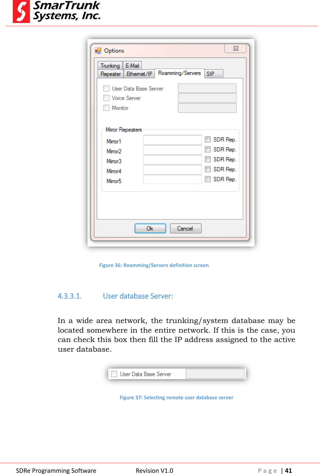
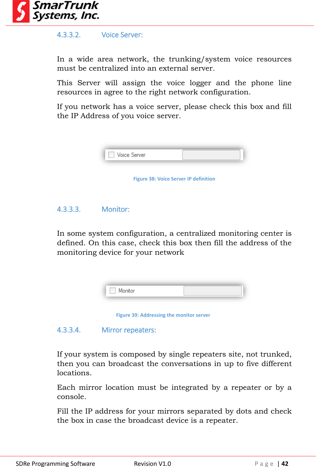
![SDRe Programming Software Revision V1.0 P a g e | 43 Figure 40: Broadcast configuration for conventional repeater sites 4.3.4. SIP Server IP configuration: On this tab, you can program the IP address of the SIP gateway. This gateway will specify the codec, protocol and routing for any communication exchanged with external switches. Check the box if you want to enable/disable the SIP service. Figure 41: SIP Server IP configuration tab To save changes press [Ok] or select other tab. If you want to cancel the modifications for this tab, press [cancel].](https://usermanual.wiki/Ranger-Communications/ST-9116D/User-Guide-2837370-Page-43.png)
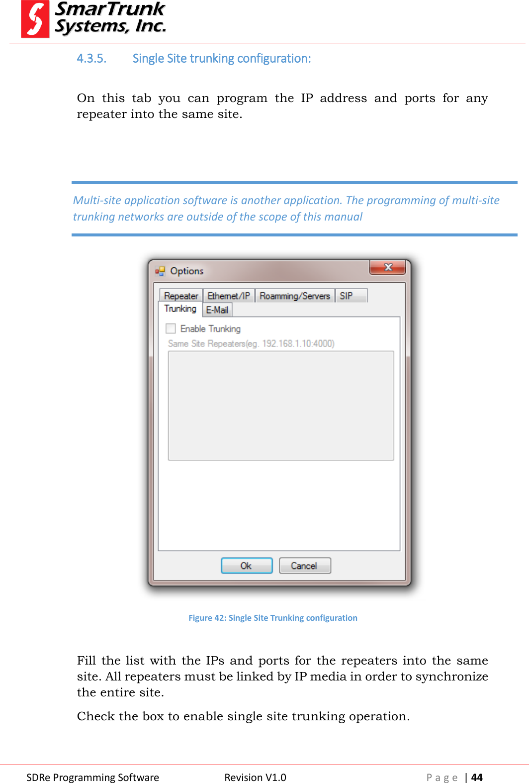
![SDRe Programming Software Revision V1.0 P a g e | 45 To save changes, press [Ok] or select other tab. If you want to cancel the modifications for this tab, press [cancel]. 4.3.6. E-mail Service configuration: On this tab, you can program the required parameters to support e-mail services. Figure 43: E-mail services configuration 4.3.6.1. Outgoing Services to the radios: Incoming mails from the Internet must be received from the repeater using POP3 service to connect to an e-mail server. Fill the Server IP address, the port and the security mode as per your POP3 service.](https://usermanual.wiki/Ranger-Communications/ST-9116D/User-Guide-2837370-Page-45.png)
![SDRe Programming Software Revision V1.0 P a g e | 46 Check Enable box to activate the service Figure 44: POP3 Service configuration 4.3.6.2. Outgoing Services to the radios: Outgoing e-mails coming from radios to the Internet must be delivered from the repeater using SMTP service. The SDR repeater has the SMPT Bridge embedded. You can activate this service by filling the SMPT server IP address, port and security mode, and then check the Enable box. Figure 45: SMPT service configuration 4.4. Repeater and File Password Protection: In most of the applications, it is important to protect programming information. To access to the password protection screen, please click on [Edit] then click into [Passwords] tab.](https://usermanual.wiki/Ranger-Communications/ST-9116D/User-Guide-2837370-Page-46.png)
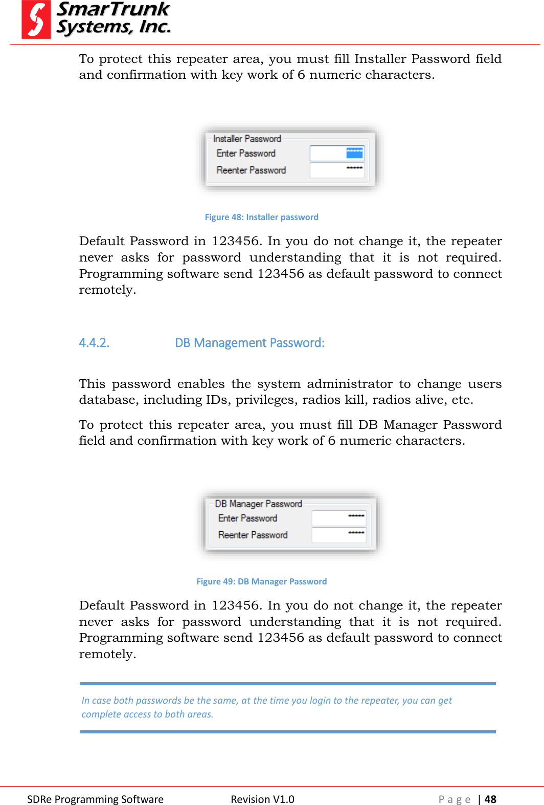
![SDRe Programming Software Revision V1.0 P a g e | 47 Figure 46: Access to Passwords programming screen As soon as you click in [Passwords], the password programming screen will be launched. Figure 47: Installer and Data Base manager password protection screen ST-91XX series offers two level of passwords protection: one for the Technicians who install the repeaters, makes the alignment, hardware programming, etc. and the second one for administrative programmers, who only needs access to the repeater user database, but no channel programming or alignment. 4.4.1. Installer Password: This password enables the technicians to change the frequency programming, align the entire repeater, and define the IP environment parameters, Monitoring, Servers, etc., in local or remote environment.](https://usermanual.wiki/Ranger-Communications/ST-9116D/User-Guide-2837370-Page-47.png)
![SDRe Programming Software Revision V1.0 P a g e | 49 4.5. CTCSS Table: The SDR repeaters supports up to 32 private groups into analog or hybrid mode. The signaling used to discriminate the groups is CTCSS. To enable a group, list the right CTCSS into the CTCSS table. Figure 50: CTCSS Table In case you do not fill any CTCSS table, the repeater operates only with the defined CTCSS on the frequency chart. 4.6. Profiles: From the main menu bar, press on [Edit] then [Profiles] to access to profiles menu.](https://usermanual.wiki/Ranger-Communications/ST-9116D/User-Guide-2837370-Page-49.png)
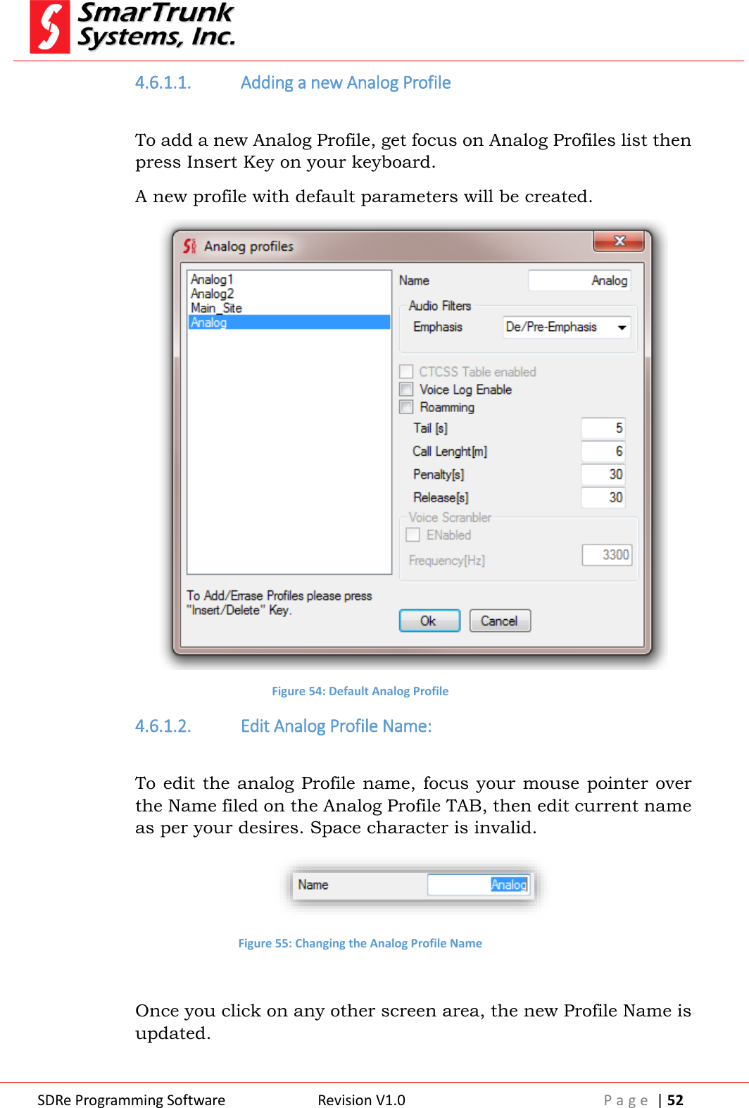
![SDRe Programming Software Revision V1.0 P a g e | 50 Figure 51: Profiles Menu Access Once you press on [Profiles], a list of possible profiles will be open. If some profiles are on grey, it is because your firmware does not support that service. 4.6.1. Analog Profiles: All common characteristic of any analog profile common to any of the channels in the repeater must be programed on this step and the associated to the right frequencies on the chart later. To access to the Analog profile menu, proceed pressing on [Menu] then [Profiles], then [Analog]](https://usermanual.wiki/Ranger-Communications/ST-9116D/User-Guide-2837370-Page-50.png)
![SDRe Programming Software Revision V1.0 P a g e | 51 Figure 52: Accessing to the Analog Profile tab Once you press on [Analog], the Analog Profile menu will be opened: Figure 53: Analog Profile TAB](https://usermanual.wiki/Ranger-Communications/ST-9116D/User-Guide-2837370-Page-51.png)
![SDRe Programming Software Revision V1.0 P a g e | 53 Press OK to save the changes. 4.6.1.3. Selecting the type of audio filters Analog signals on SDR repeaters can be fltered on four modes. The standard one is the de/pre-emphasized, but you also can select other modes for some special application. Press on the Audio Filters side arrow to slide down the menu. Figure 56: Audio Filters selection for analog profiles Flat: No filtering for RX or TX. The modulation audio is just the discriminator signal (flat) from the receiver. This mode cannot be used when the repeater integrates a network environment because the audio exchanged to the IP or monitor should be emphasized. De-Emphasis: Received signals are de-emphasized then modulated in flat format. Pre-Emphasized: Received signal is left flat and the TX modulation on emphasized. De/Pre-emphasized: Received signals are de-emphasized processed on this condition then emphasized again for transmit. This mode is the standard one. To store this option, click on any part of the tab. To save the value, press [Ok] or Cancel if you want to discard the changes. 4.6.1.4. CTCSS table enabled If you want to use a pre-loaded CTCSS table, overriding any CTCSS defined on the frequency chart, check this box.](https://usermanual.wiki/Ranger-Communications/ST-9116D/User-Guide-2837370-Page-53.png)
![SDRe Programming Software Revision V1.0 P a g e | 54 Figure 57: Enable CTCSS table on Analog Profile To store this option, click on any part of the tab. To save the value, press [Ok] or Cancel if you want to discard the changes. 4.6.1.5. Enable the Voice Log Service on Analog Profiles ST-9116 repeater can log any voice conversation. If you want to activate this service for a particular analog profile, please check this box. Voice is stored on the SD memory attached to the unit. Old files are deleted automatically if the memory is full. If no memory, the service is deactivated automatically. Figure 58: Voice Log Enabled for Analog Profiles To store this option, click on any part of the tab. To save the value, press [Ok] or Cancel if you want to discard the changes. 4.6.1.6. Enable the Roaming Service on Analog Profiles If you want to integrate a network, using this channel as a site of your wide area coverage, then you must check this box. Once this box is checked, audio from this repeater is processed and shared through IP between any other site on the network. Figure 59: Roaming Service Activation for Analog Profiles](https://usermanual.wiki/Ranger-Communications/ST-9116D/User-Guide-2837370-Page-54.png)
![SDRe Programming Software Revision V1.0 P a g e | 55 To store this option, click on any part of the tab. To save the value, press [Ok] or Cancel if you want to discard the changes. 4.6.1.7. Setup the repeater tail Fill this field with the length desired for repeater tail. 0 second means no tail. Max value is 255 seconds. Figure 60: Repeater tail setup To store the value, click on any part of the tab. To save the value, press [Ok] or Cancel if you want to discard the changes. 4.6.1.8. Enable the Roaming Service on Analog Profiles If you want set a limit of minutes for a call length, then fill this field. 0 minute means no limit. Absolute Max call length is 255 minutes. Figure 61: Repeater MAX Call Length To store the value, click on any part of the tab. To save the value, press [Ok] or Cancel if you want to discard the changes. 4.6.1.9. Repeater Penalty setup If call length limit is reached, the repeater may apply a penalty for the CTCSS tone (group) who has reached the limit. For example, if a particular group, who uses one of the tones defined on the CTCSS table, reaches the max length accepted for this profile, that tone remains inactive by the amount of seconds defined on this step.](https://usermanual.wiki/Ranger-Communications/ST-9116D/User-Guide-2837370-Page-55.png)
![SDRe Programming Software Revision V1.0 P a g e | 56 Max penalty length is 255 seconds. 0 seconds of penalty means no penalty, so the group can setup a new call immediately. Figure 62: Penalty for traffic control on Analog Profiles To store the value, click on any part of the tab. To save the value, press [Ok] or Cancel if you want to discard the changes. 4.6.1.10. Release time for time-out timer reset If call length limit is active (Call Length timer not equal to 0), the repeater may apply a penalty for the CTCSS tone who reached the limit. This parameter specifies the time without any activity of that group to reset the time out timer, which controls the max call length. To setup this value, please fill the field. Figure 63: Release time for Traffic Control on Analog Profiles Max Release time length is 255 seconds. 0 seconds of release means instant reset of the call length timer. To store the value, click on any part of the tab. To save the value, press [Ok] or Cancel if you want to discard the changes. 4.6.1.11. Voice inversion encryption setup ST-9116 supports voice inversion encryption for analog profiles. If you want to enable it, please check the [Enabled] box then input the right voice inversion sub-carrier for this profile.](https://usermanual.wiki/Ranger-Communications/ST-9116D/User-Guide-2837370-Page-56.png)
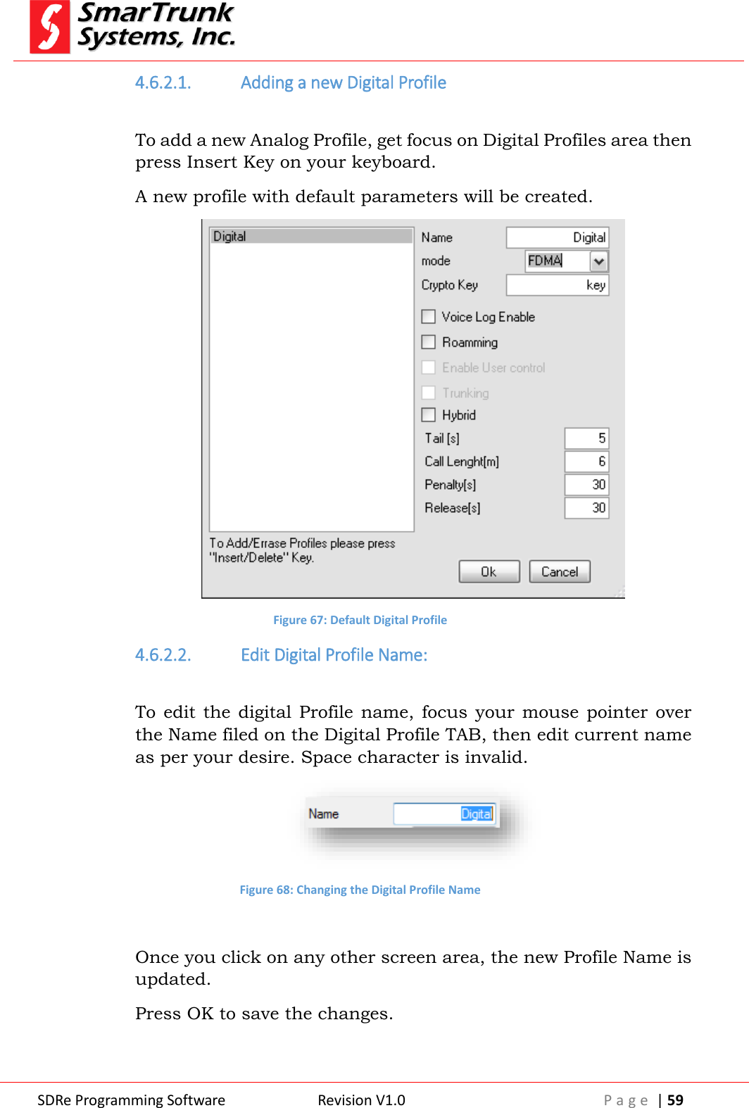
![SDRe Programming Software Revision V1.0 P a g e | 57 Figure 64: Voice Inversion encryption configuration To store the value, click on any part of the tab. To save the value, press [Ok] or Cancel if you want to discard the changes. 4.6.2. Digital Profiles: All common characteristic of any digital profile related to any of the channels in the repeater, must be programed on this step, and then associated to the right frequencies on the chart. To access to the Digital profile menu, proceed pressing on [Menu] then [Profiles], then [Digital]](https://usermanual.wiki/Ranger-Communications/ST-9116D/User-Guide-2837370-Page-57.png)
![SDRe Programming Software Revision V1.0 P a g e | 58 Figure 65: Accessing to the Analog Profile tab Once you press on [Digital], the Digital Profile menu will be opened: Figure 66: Digital Profile TAB](https://usermanual.wiki/Ranger-Communications/ST-9116D/User-Guide-2837370-Page-58.png)
![SDRe Programming Software Revision V1.0 P a g e | 60 4.6.2.3. Selecting the type of Digital Modulation Digital Emissions on SDR repeaters can be used on three different modes. FDMA (Frequency Domain Multiple Access), TDMA (Time Domain Multiple Access) or Simplex mode (Transmit and receive on the same frequency. Press on the Digital Mode arrow to slide down the menu. Figure 69: Digital Mode selection for Digital profile FDMA: Transmits a single continuous 4FSK carrier @ 4800bps using ultra narrow band (6.25 Khz Bandwidth) TDMA: Transmits two slots over a continuous carrier of 9600 bps using a narrowband channel (12.5Khz Bandwidth) SIMPLEX: Similar to TDMA but the carrier is not continuous. Repeater receives on slot 0 and transmits the same information on slot 1, using the same frequency for TX and RX Simplex mode. To store this option, click on any part of the tab. To save the value, press [Ok] or [Cancel] if you want to discard the changes. 4.6.2.4. Crypto Key definition SDR protocol improves a high security encryption for voice and data. The encryption is encoded and decoded using a 128bits mask, which must be defined on this tab. Figure 70: Crypto Key for Digital Profile](https://usermanual.wiki/Ranger-Communications/ST-9116D/User-Guide-2837370-Page-60.png)
![SDRe Programming Software Revision V1.0 P a g e | 61 To simplify the key management, you must type any string up to 16 characters length. This key is case sensitive: Figure 71: Sample of Crypto Key for digital profiles To store this option, click on any part of the tab. To save the value, press [Ok] or Cancel if you want to discard the changes. 4.6.2.5. Enable the Voice Log Service on Digital Profiles ST-9116 repeater can log any voice conversation. If you want to activate this service for a particular analog profile, please check this box. Voice is stored on the SD memory attached to the unit. Old files are deleted automatically if the memory is full. If no memory, the service is deactivated automatically. Figure 72: Voice Log Enabled for Digital Profiles To store this option, click on any part of the tab. To save the value, press [Ok] or Cancel if you want to discard the changes. 4.6.2.6. Enable the Roaming Service on Digital Profiles If you want to integrate a network, using this channel as a site of your wide area coverage, then you must check this box. Once this box is checked, audio form, this repeater is processed and shared through IP between any other site on the network.](https://usermanual.wiki/Ranger-Communications/ST-9116D/User-Guide-2837370-Page-61.png)
![SDRe Programming Software Revision V1.0 P a g e | 62 Figure 73: Roaming Service Activation for Digital Profiles To store this option, click on any part of the tab. To save the value, press [Ok] or Cancel if you want to discard the changes. 4.6.2.7. Hybrid Mode SDR protocol supports analog and digital modulations on the same channel. Check this box if you want to allow the repeater to support analog and digital radios over the same channel. Figure 74: Hybrid mode activation To store this option, click on any part of the tab. To save the value, press [Ok] or Cancel if you want to discard the changes. 4.6.2.8. Setup the repeater tail Fill this field with the desired repeater tail length. 0 second means no tail. Max value is 255 seconds. Figure 75: Repeater tail setup for Digital Profiles To store the value, click on any part of the tab. To save the value, press [Ok] or Cancel if you want to discard the changes.](https://usermanual.wiki/Ranger-Communications/ST-9116D/User-Guide-2837370-Page-62.png)
![SDRe Programming Software Revision V1.0 P a g e | 63 4.6.2.9. Enable the Call Length control on Digital Profiles If you want Set a limit of minutes for a call length, then fill this field. 0 minute means no limit. Absolute Max call length is 255 minutes. Figure 76: Repeater MAX Call Length on Digital Profiles To store the value, click on any part of the tab. To save the value, press [Ok] or Cancel if you want to discard the changes. 4.6.2.10. Repeater Penalty setup on Digital Profiles If Call length limit is reached, the repeater may apply a penalty for the digital ID who reached the limit. For example, if a particular group, who uses the channel, reaches the max length accepted for this profile, that group remains inactive by the amount of seconds defined on this step. Max penalty length is 255 seconds. 0 seconds of penalty means no penalty, so the group can setup a new call immediately. Figure 77: Penalty for traffic control on Analog Profiles To store the value, click on any part of the tab. To save the value, press [Ok] or Cancel if you want to discard the changes. 4.6.2.11. Release time for time-out timer reset for Digital Profiles If Call length limit is active (Call Length timer not equal to 0), the repeater may apply a penalty for the group who has reached the limit.](https://usermanual.wiki/Ranger-Communications/ST-9116D/User-Guide-2837370-Page-63.png)
![SDRe Programming Software Revision V1.0 P a g e | 64 This parameter specify the time without any activity of that group to reset the time out timer who controls the max call length. To setup this value, please fill the field. Figure 78: Release time for Traffic Control on Digital Profiles Max Release time length is 255 seconds. 0 seconds of release means instant reset of the call length timer. To store the value, click on any part of the tab. To save the value, press [Ok] or Cancel if you want to discard the changes. 5. Adding a channel to a memory channel To add a new channel to the repeater, please click on the first empty tag name under the last channel tag into the list Figure 79: adding a new channel tag Type there the tag name to be assigned to the new channel, for example TEST, then click on the RX frequency field for the new channel recently created. The programming software will complete the frequencies and signaling as per default, so please overwrite it with you desired settings.](https://usermanual.wiki/Ranger-Communications/ST-9116D/User-Guide-2837370-Page-64.png)
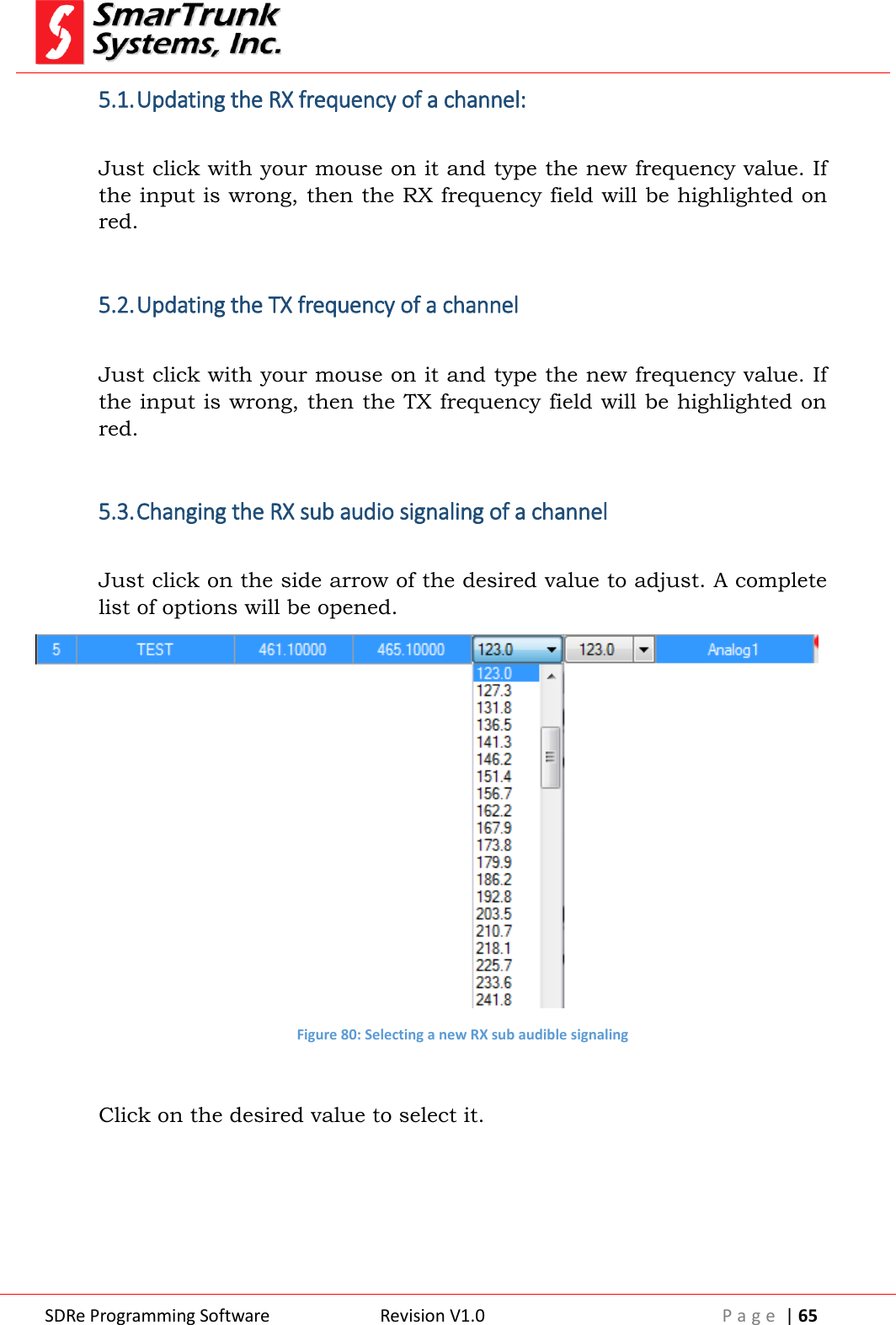
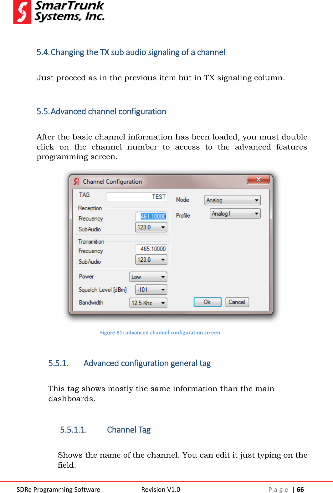
![SDRe Programming Software Revision V1.0 P a g e | 67 Figure 82: Channel tag Once selected the right parameter, press [Ok] to save it or [Cancel] to exit. 5.5.1.2. RX frequency: Shows the RX frequency for this channel. You can edit it by direct typing over the field. Figure 83: Channel RX information Once selected the right parameter, press [Ok] to save it or [Cancel] to exit. 5.5.1.3. RX sub Audio Signaling: Shows the CTCSS or DCS information for the current channel. Click on the side arrow then select a different one if you want to change it. Once selected the right parameter, press [Ok], press over to save it or [Cancel] to exit. 5.5.1.4. TX frequency: Shows the TX frequency for this channel. You can edit it by direct typing over the field.](https://usermanual.wiki/Ranger-Communications/ST-9116D/User-Guide-2837370-Page-67.png)
![SDRe Programming Software Revision V1.0 P a g e | 68 Figure 84: Channel TX information Once selected the right parameter, press [Ok] to save it or [Cancel] to exit. 5.5.1.5. TX sub Audio Signaling: Shows the CTCSS or DCS information for the current channel. Click on the side arrow then select a different one if you want to change it. Once selected the right parameter, press [Ok] to save it or [Cancel] to exit. 5.5.1.6. Channel Power selection Shows the current power level assigned to the channel. To change it, press on the side arrow then choose your desired level. Figure 85: Channel Power selection Once selected the right parameter, press [Ok] to save it or [Cancel] to exit.](https://usermanual.wiki/Ranger-Communications/ST-9116D/User-Guide-2837370-Page-68.png)
![SDRe Programming Software Revision V1.0 P a g e | 69 5.5.1.7. Squelch Sensitivity Shows the current squelch level for current channel. It means the absolute threshold level to consider if a carrier is present on the receiver. Press on the side arrow to select a new value from a drop down list if you want to change it. Figure 86: Squelch sensitivity To select a value, scroll the list then click on the desired threshold level. Once selected the right parameter, press [Ok] to save it or [Cancel] to exit. 5.5.1.8. Channel bandwidth In analog mode, the channel bandwidth can be selected as per used desire. Figure 87: Channel Bandwidth Selection](https://usermanual.wiki/Ranger-Communications/ST-9116D/User-Guide-2837370-Page-69.png)
![SDRe Programming Software Revision V1.0 P a g e | 70 Press on the side arrow to change it if you want. Possible values: 12.5 KHz or 25 KHz. Depending on your region it is possible than 25 KHz bandwidth is not possible to be selected. Once selected the right parameter, press [Ok] to save it or [Cancel] to exit. 5.5.1.9. Channel mode selection This option lets you assign existing signaling profile and modulation type for the current channel. Figure 88: Channel mode selection Once selected the right parameter, press [Ok] to save it or [Cancel] to exit. 5.5.1.10. Channel Profile Selection: The right profile, previously defined on 4.6.1 or 4.6.2., must be attached to the current channel by pressing the side arrow on the Profile Field. A list the pre-defined profiles will be listed. Figure 89: type of modulation Click over the right one to select it. Once selected the right parameter, press [Ok] to save it or [Cancel] to exit.](https://usermanual.wiki/Ranger-Communications/ST-9116D/User-Guide-2837370-Page-70.png)
![SDRe Programming Software Revision V1.0 P a g e | 71 6. Reading the Repeater programming from the device All the information already downloaded to your radio can be retrieved anytime. In case that information has been protected by password, you must know such critical information to start the reading process. To read the radio file from the repeater, you must connect the radio to the USB port on your computer or by IP, as previously defined on the Programming Software configuration (see 2.2.1), then you can use the shortcut in the quick access bar or you go through [Repeater] then click on Read Repeater. F2 key on your computer keyboard can be used as a shortcut also. Figure 90: Accessing to read the repeater Once you press on [Read Repeater], the information stored in the device will be loaded to your programming software automatically. As soon as the process starts, a progress bar will show you the process evolution. When you download a Repeater file from the Repeater, previous information into your programming software will be overwritten. Please ensure you have already saved that information before proceed to download from the repeater Note: 12- Downloading the repeater fill will overwrite existing information in Programming Software](https://usermanual.wiki/Ranger-Communications/ST-9116D/User-Guide-2837370-Page-71.png)
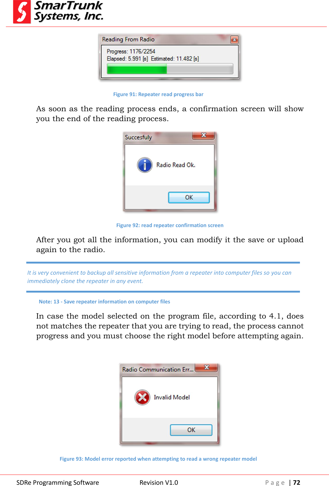
![SDRe Programming Software Revision V1.0 P a g e | 73 7. Writing a radio file Once you get a program into your programming software ready to upload to a repeater, you must connect the device to the USB port on your computer or remotely through a TCP/IP network, then you can use the shortcut in the quick access bar or you go through [Repeater] then click on [Write Repeater]. F3 key on your computer keyboard can be used as a shortcut also. Figure 94: Accessing to write the repeater Once you press on [Write Repeater], the information stored in the programming software will be uploaded to your repeater automatically. As soon as the process starts, a progress bar will let you know the process ongoing. Figure 95: Writing to the repeater progress bar As soon as the process ends, a pop up screen will notify the success process.](https://usermanual.wiki/Ranger-Communications/ST-9116D/User-Guide-2837370-Page-73.png)
![SDRe Programming Software Revision V1.0 P a g e | 74 Figure 96: Repeater write confirmation screen Repeater will do a power cycle to load the new parameters after a read or write process. 8. Repeater Alignment Refer to Service manual for alignment procedure. 9. Repeater factory Reset In case the repeater has been realigned by somebody who does not understand the procedure correctly or any other problem, which may affect to the repeater performance, you can reset as per initial factory settings. This process will erase all the information on your repeater, which cannot be recovered except from backup on computer files. To proceed to reset the repeater as per factory default, please click on [Repeater] then [Factory Reset] Attempting to upload to a radio will fail if the information generated with the programming software is not for such radio model. Note: 14- Model mismatch reports uploading error.](https://usermanual.wiki/Ranger-Communications/ST-9116D/User-Guide-2837370-Page-74.png)
![SDRe Programming Software Revision V1.0 P a g e | 75 Figure 97: Accessing to restore factory default settings As soon as you click on [Factory Reset], a warning message will alert you about the process ready to go. If you are not sure, please press [Cancel]. If you agree, please press [Yes] to continue. Figure 98: warning message before restoring factory default As soon as you press [Yes], the process starts. It demands only two seconds, and then the confirmation message is displayed: Figure 99: Factory default settings confirmation](https://usermanual.wiki/Ranger-Communications/ST-9116D/User-Guide-2837370-Page-75.png)
![SDRe Programming Software Revision V1.0 P a g e | 76 As soon as this process ends, the radio will do a power cycle to load the new parameters. 10. Repeater Firmware Update: Smartrunk will continue working into the new features and services development for our repeaters so frequently you will find firmware updates into our web site. To download a new firmware to you repeater, once you have downloaded it into your computer, please clock on [Repeater] then [FW Update] Figure 100: Accessing to Repeater firmware update screen A soon as you click on [FW Update] a new screen will pop up. Figure 101: Repeater FW Update application screen To find the new firmware to be downloaded to the repeater press to proceed to open the Windows Explorer to look for the new file previously downloaded to your computer.](https://usermanual.wiki/Ranger-Communications/ST-9116D/User-Guide-2837370-Page-76.png)
![SDRe Programming Software Revision V1.0 P a g e | 77 Surf in your computer to select the desired file then connect you repeater to your computer USB port or through a TCP/IP network connection and then press [Start] to initiate the firmware update process. A progress bar will show you the process progress. Figure 102: Firmware update progress screen As soon as it finishes, the repeater will do a power cycle automatically to load the new firmware. 11. Exit from Programming software To exit from the programming software please proceed through [File] then [Exit] Uploading a wrong firmware to your repeater may cause a permanent damage to the circuitry. Please verify several times that you are ready to upload a firmware version corresponding to your radio model. Note: 15 - Wrong model firmware upload warning](https://usermanual.wiki/Ranger-Communications/ST-9116D/User-Guide-2837370-Page-77.png)
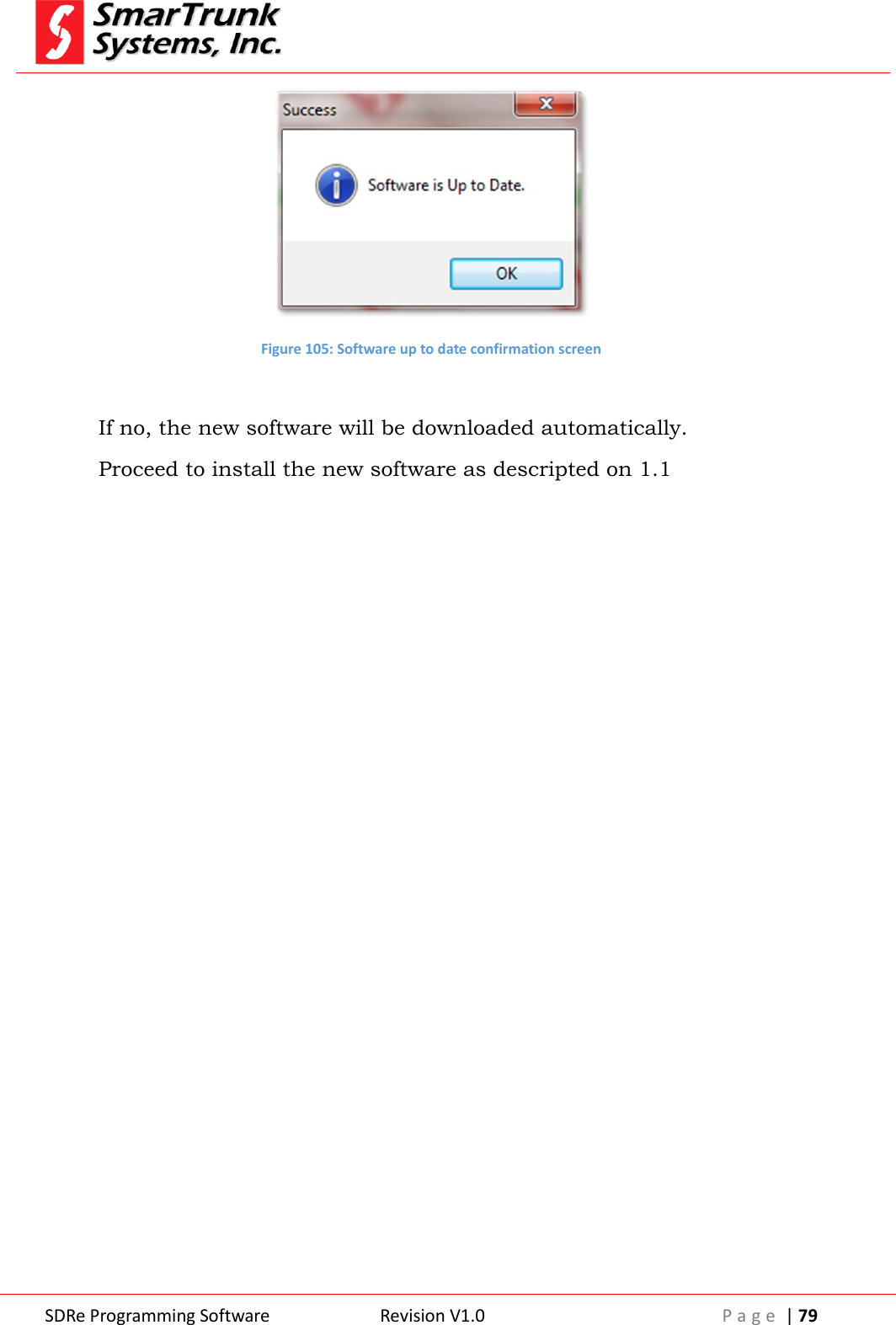
![SDRe Programming Software Revision V1.0 P a g e | 78 Figure 103: Exit from SDR programming software 12. Manual software update You can check for new updates by clicking on [Help] then [Software Update] Figure 104: Manually checking firmware update The software will look for the latest release in our web site. If your software is up to date, then a confirmation screen will pop up. Before exit, verify if the current data has been saved. Any change will be lost. Note: 16 - lost data on exit warning note](https://usermanual.wiki/Ranger-Communications/ST-9116D/User-Guide-2837370-Page-78.png)