Robert Bosch NBC-265-W WIRELESS IP CAMERA User Manual NBC 265 W en
Robert Bosch Taiwan Co., Ltd. WIRELESS IP CAMERA NBC 265 W en
UserManual.wiki
>
Robert Bosch
>
NBC-265-W User Manual
>
Users Manual 265 1
Contents
1.
Users Manual 255 1
2.
Users Manual 255 2
3.
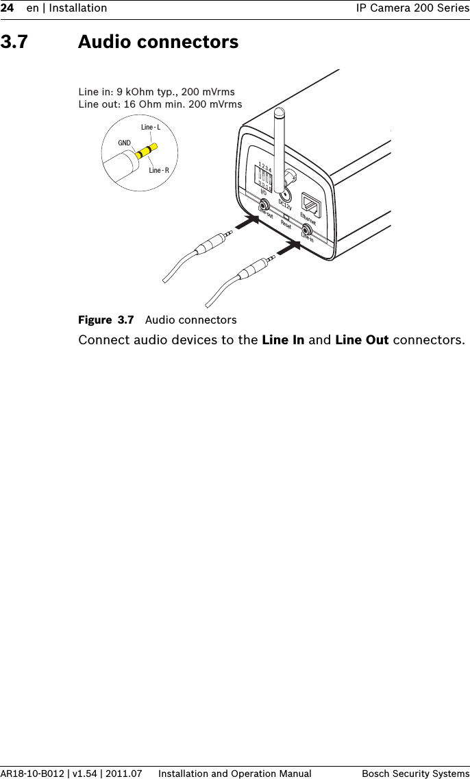
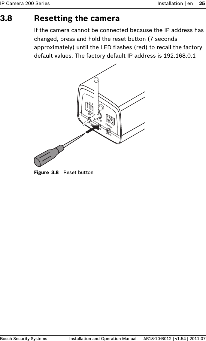
Users Manual 265 1
4.
Users Manual 265 2
Users Manual 265 1
Navigation menu
Upload a User Manual
Namespaces
Wiki Guide
HTML
PDF
Info
Views
User Manual
Discussion / Help
Navigation