Robertshaw Controls d b a Invensys Home Control Systems EMSL-200 Wireless Load Control Meter User Manual TD2001
Robertshaw Controls Company d/b/a Invensys Home Control Systems Wireless Load Control Meter TD2001
UserManual.wiki
>
Robertshaw Controls d b a Invensys Home Control Systems
>
EMSL 200 User Manual
User Manual
Navigation menu
Upload a User Manual
Namespaces
Wiki Guide
HTML
PDF
Info
Views
User Manual
Discussion / Help
Navigation
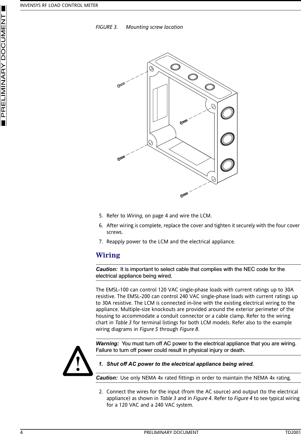
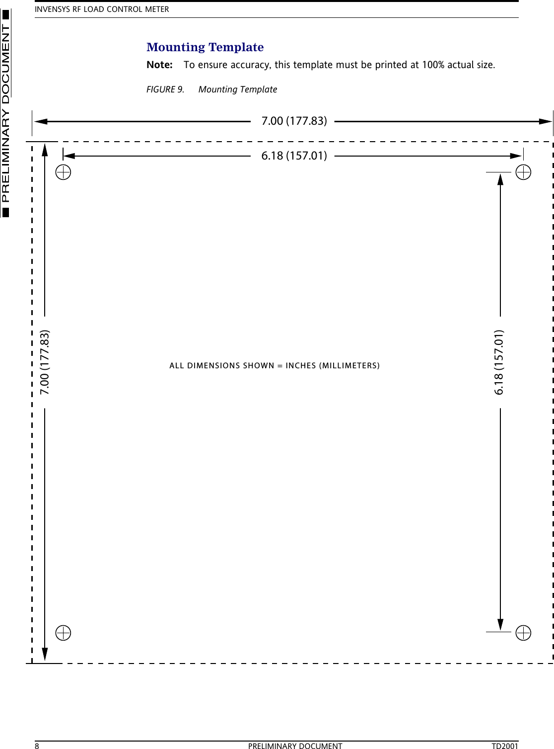
![MOUNTING8/6/02 PRELIMINARY DOCUMENT 3MountingMounting holes are provided at each corner to secure the LCM to a flat surface. Figure 4 shows mounting dimensions. Refer to FIGURE 9. Mounting Template, on page 8 for an installation template at actual size.FIGURE 2. Enclosure dimensions1. Select a flat mounting location.2. Mark and prepare the surface mounting holes, using dimensions above or use the template in FIGURE 9. Mounting Template, on page 8.3. Remove the cover from the LCM enclosure by removing the four cover attaching screws in the corners of the cover.4. Insert mounting screws down through the same holes that the cover screws came out of and securely fasten the LCM enclosure to the flat surface.6.90 [175.36]7.00 [177.83]5.43 [138.03]5.50 [139.58]3.94 [100.00]6.18 [157.01]1.42 [36.09]1.00 [25.40]3.94 [100.00]1.99 [50.50]6.18 [157.03]5.51 [140.00]5.00 [127.00]END VIEWREAR VIEW0.39 [10.00]5.51 [140.00]5.43 [138.03]7.00 [177.83]1.97 [50.00]3.02 [76.62]MOUNTING HOLESMOUNTING HOLESNOTE: DIMENSIONS ARE IN INCHES (MILLIMETERS)](https://usermanual.wiki/Robertshaw-Controls-d-b-a-Invensys-Home-Control-Systems/EMSL-200/User-Guide-267609-Page-3.png)