Rohrback Cosasco Systems ER200 Hazardous Area Electrical Resistance Corrosion Monitoring Data-logger User Manual 1
Rohrback Cosasco Systems Hazardous Area Electrical Resistance Corrosion Monitoring Data-logger Users Manual 1
Contents
- 1. Users Manual 2
- 2. Users Manual 1
Users Manual 1
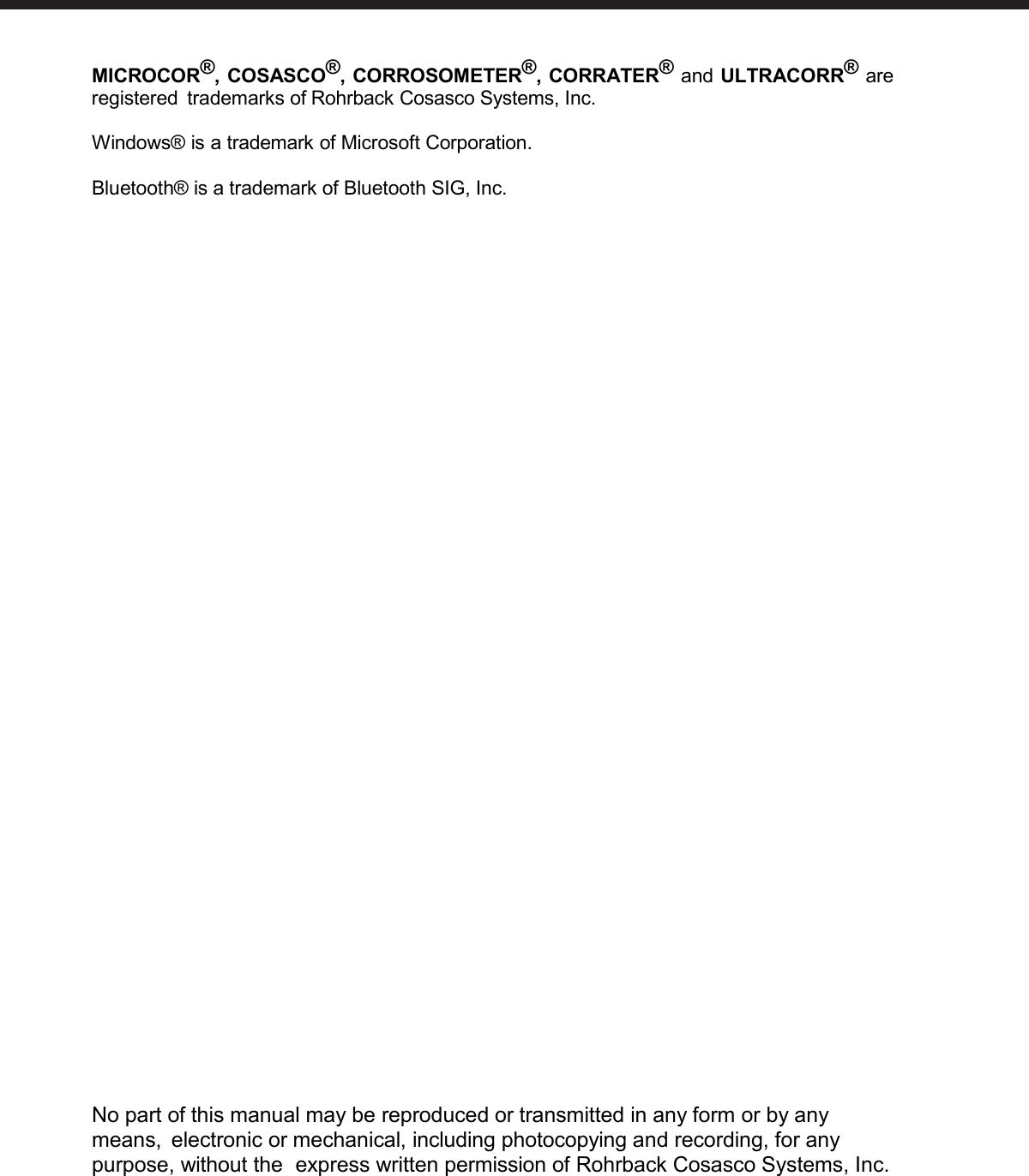
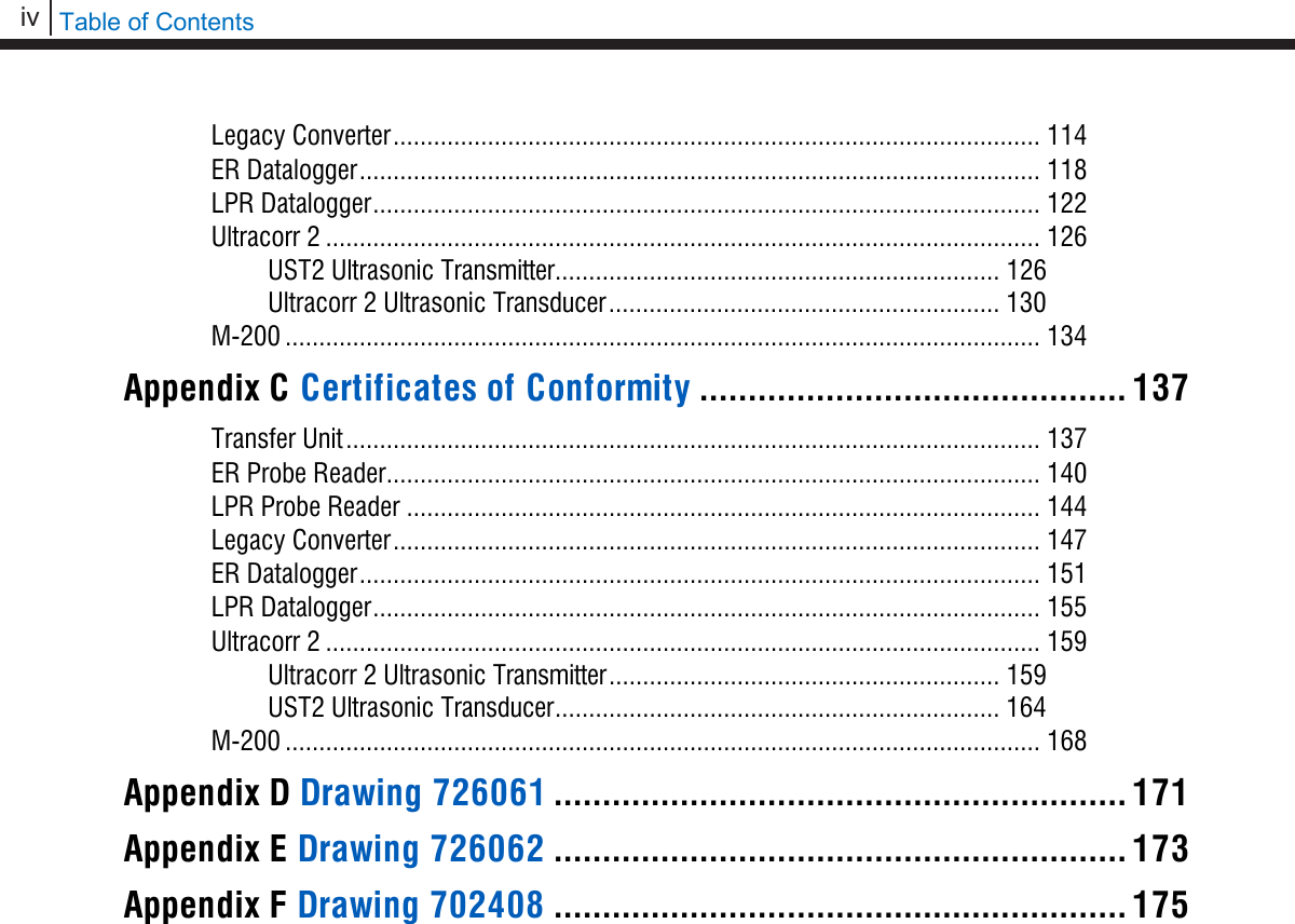

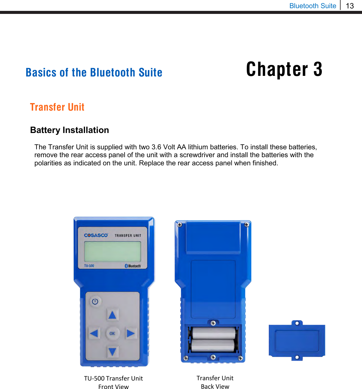
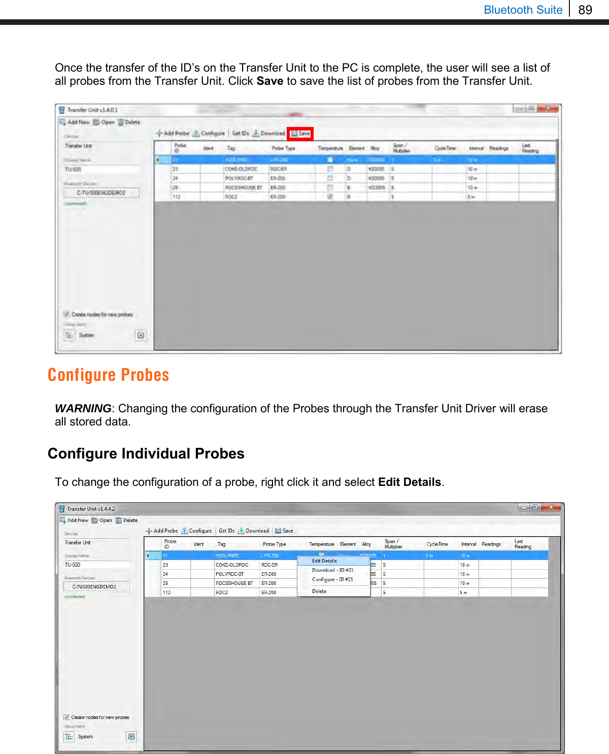
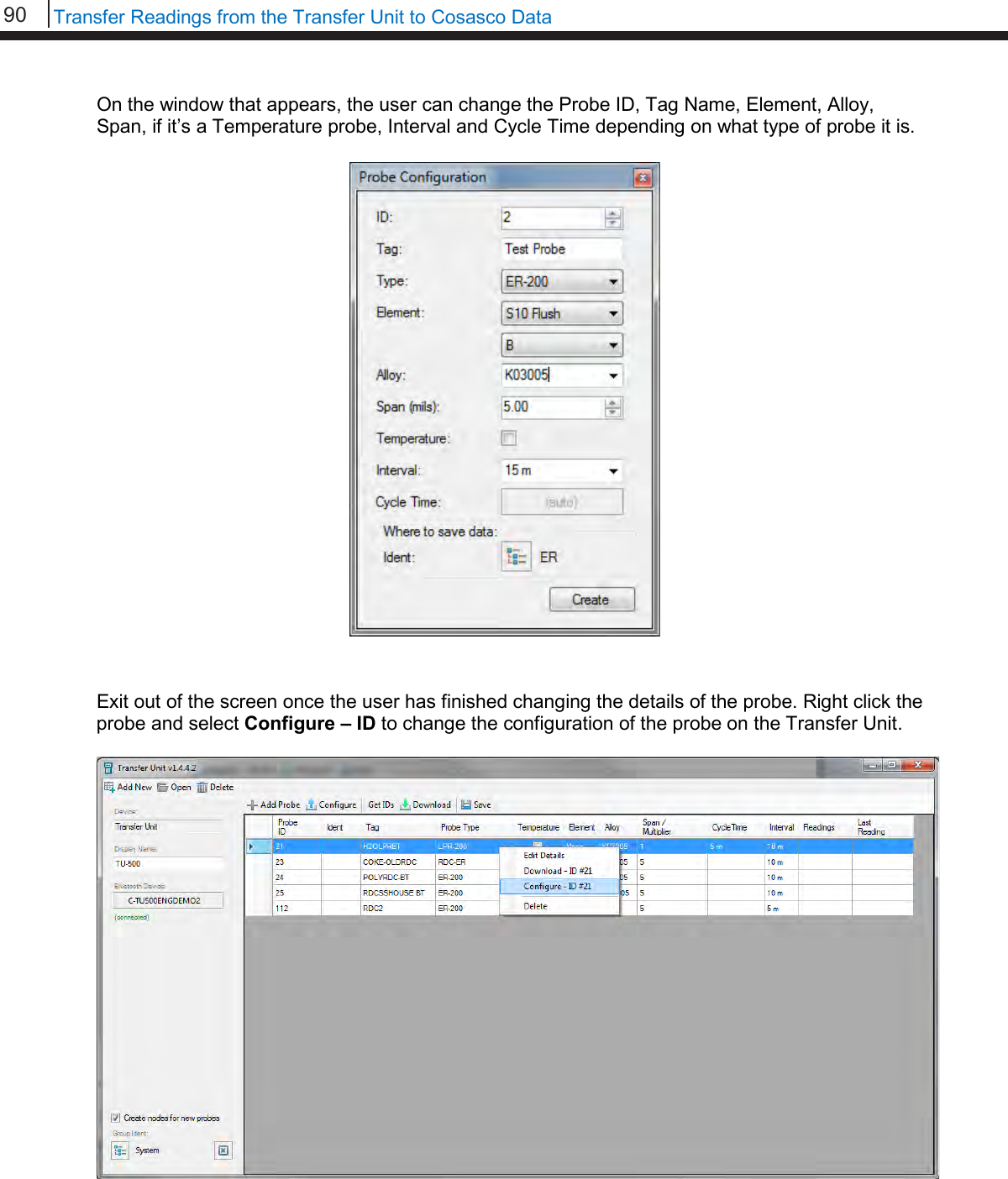
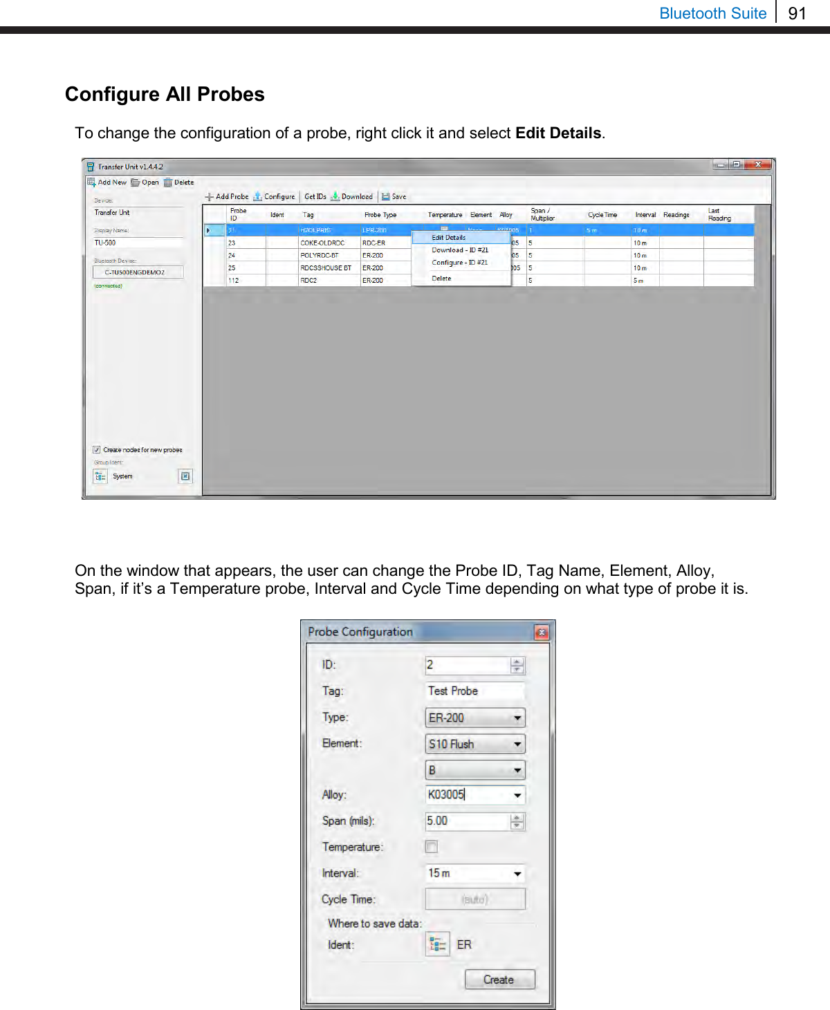
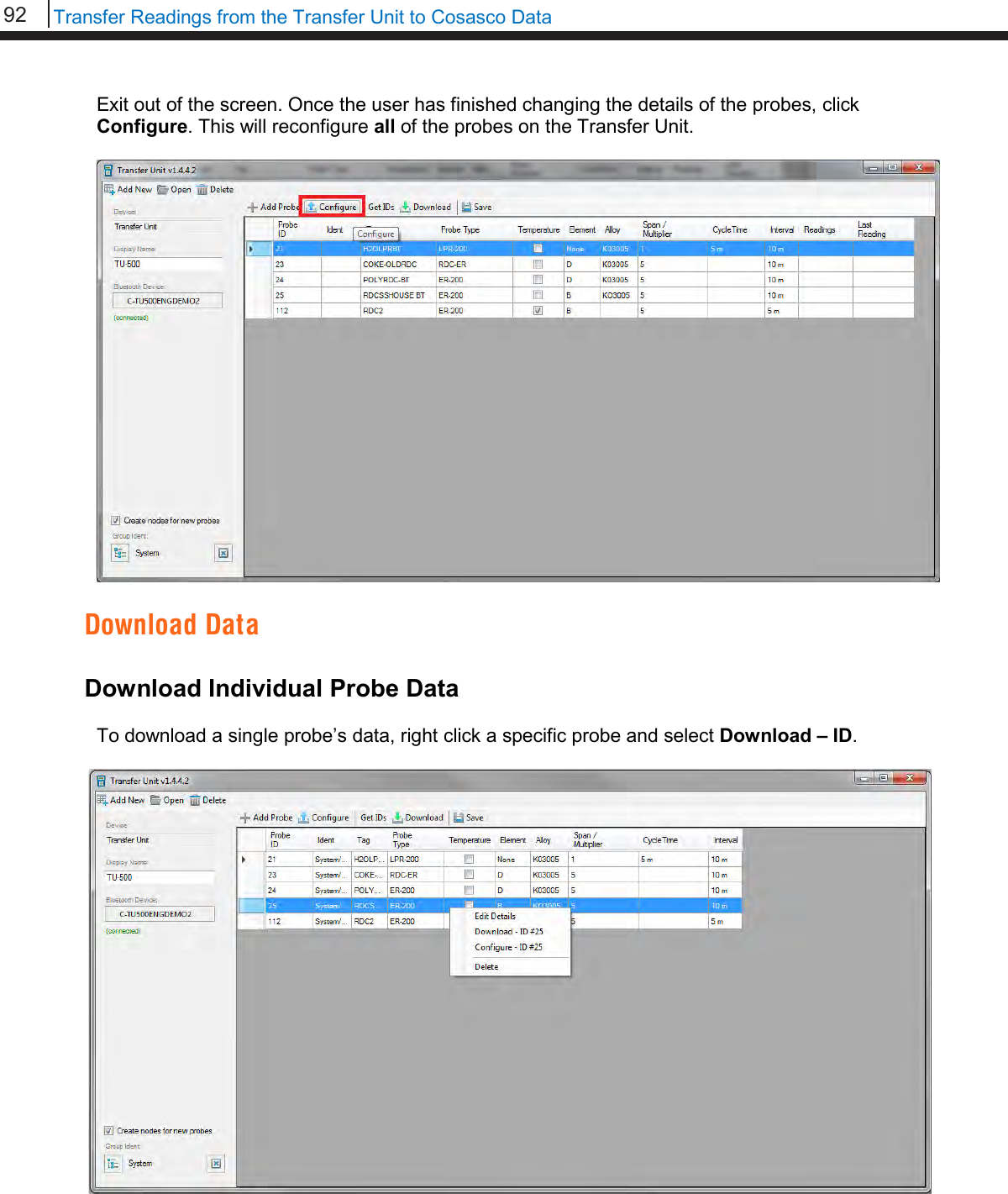
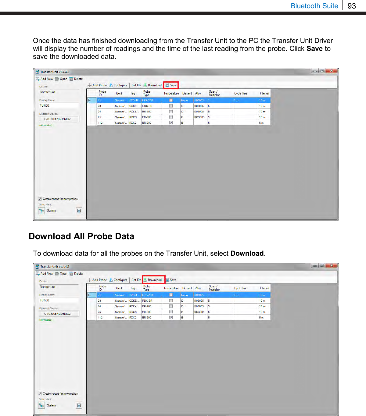
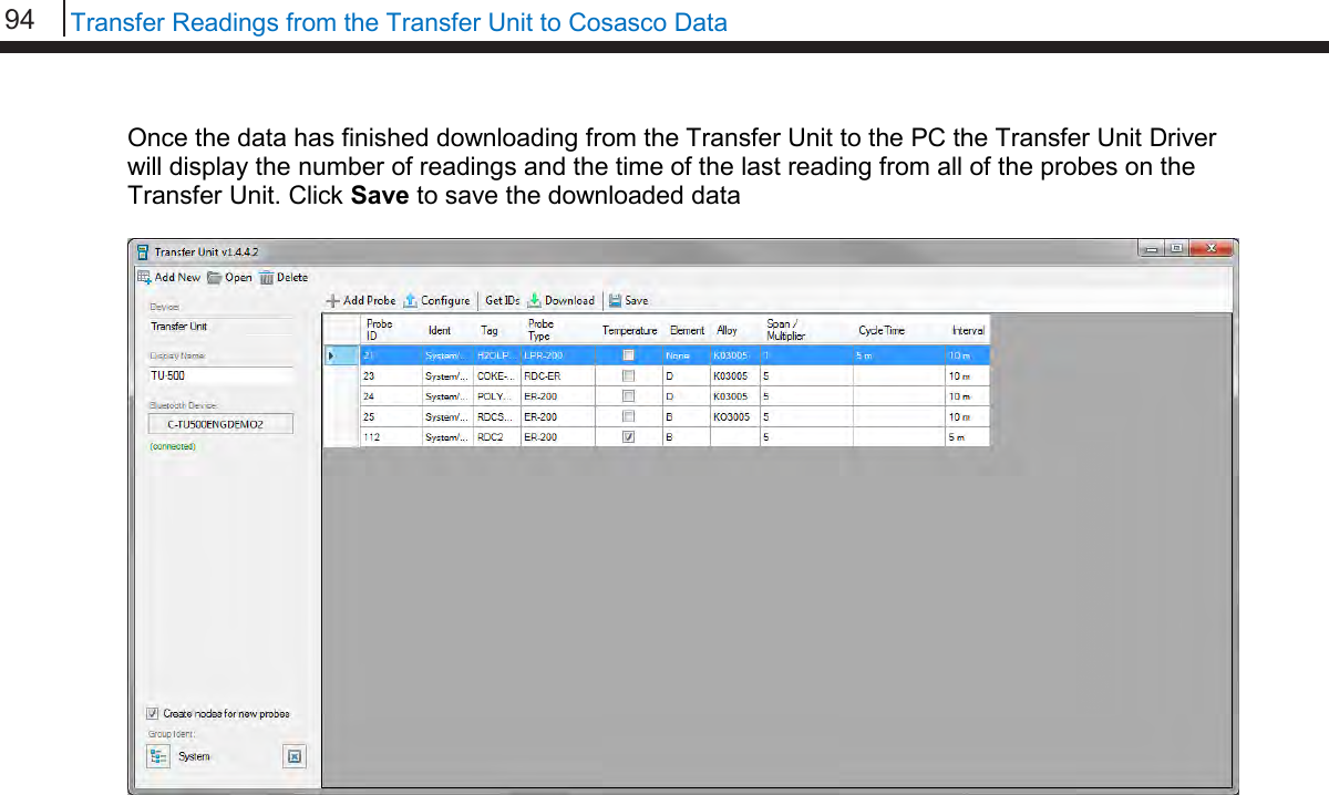
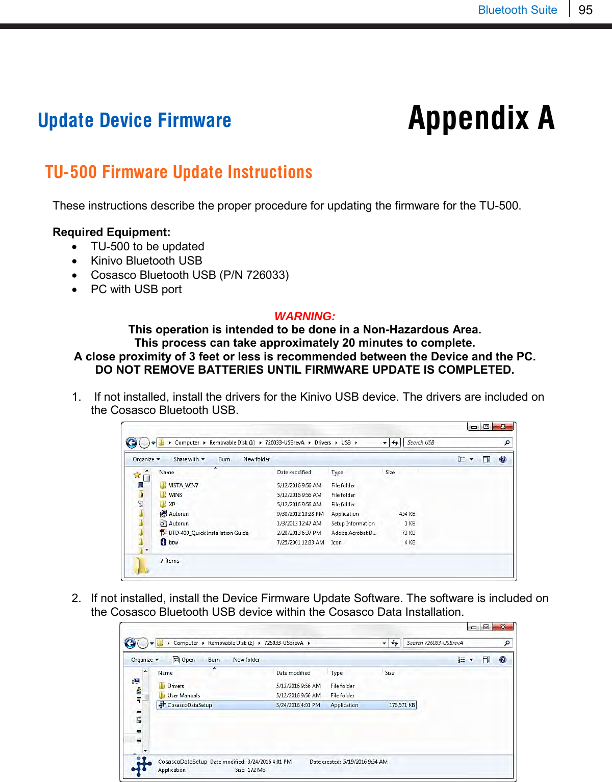
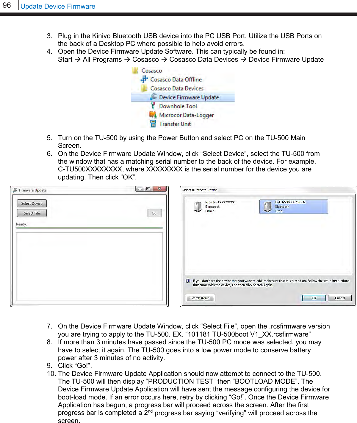
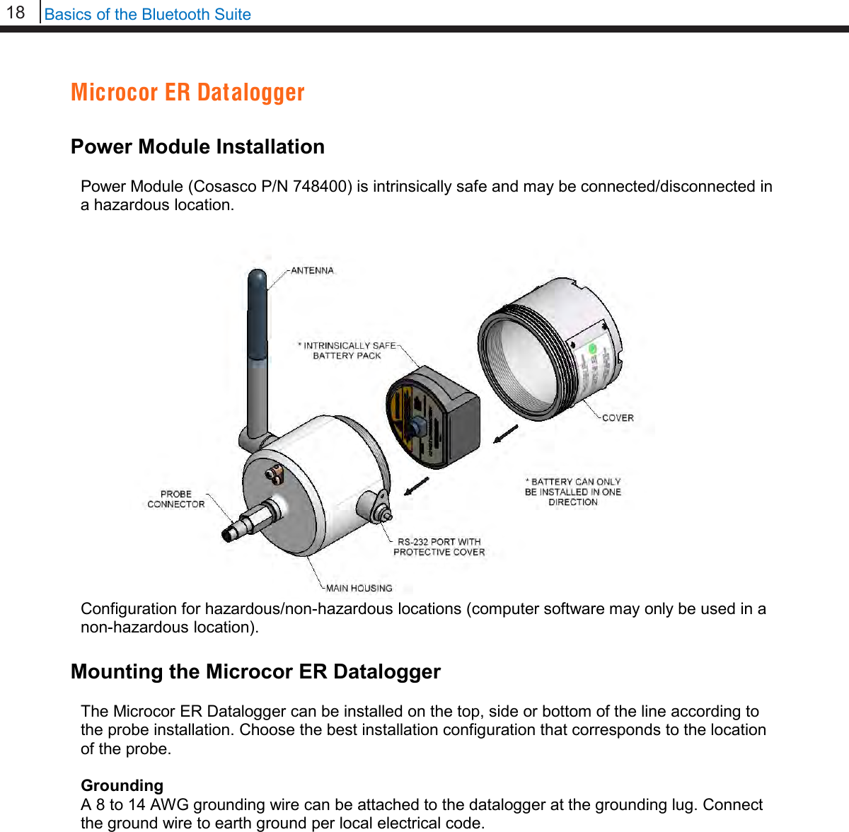
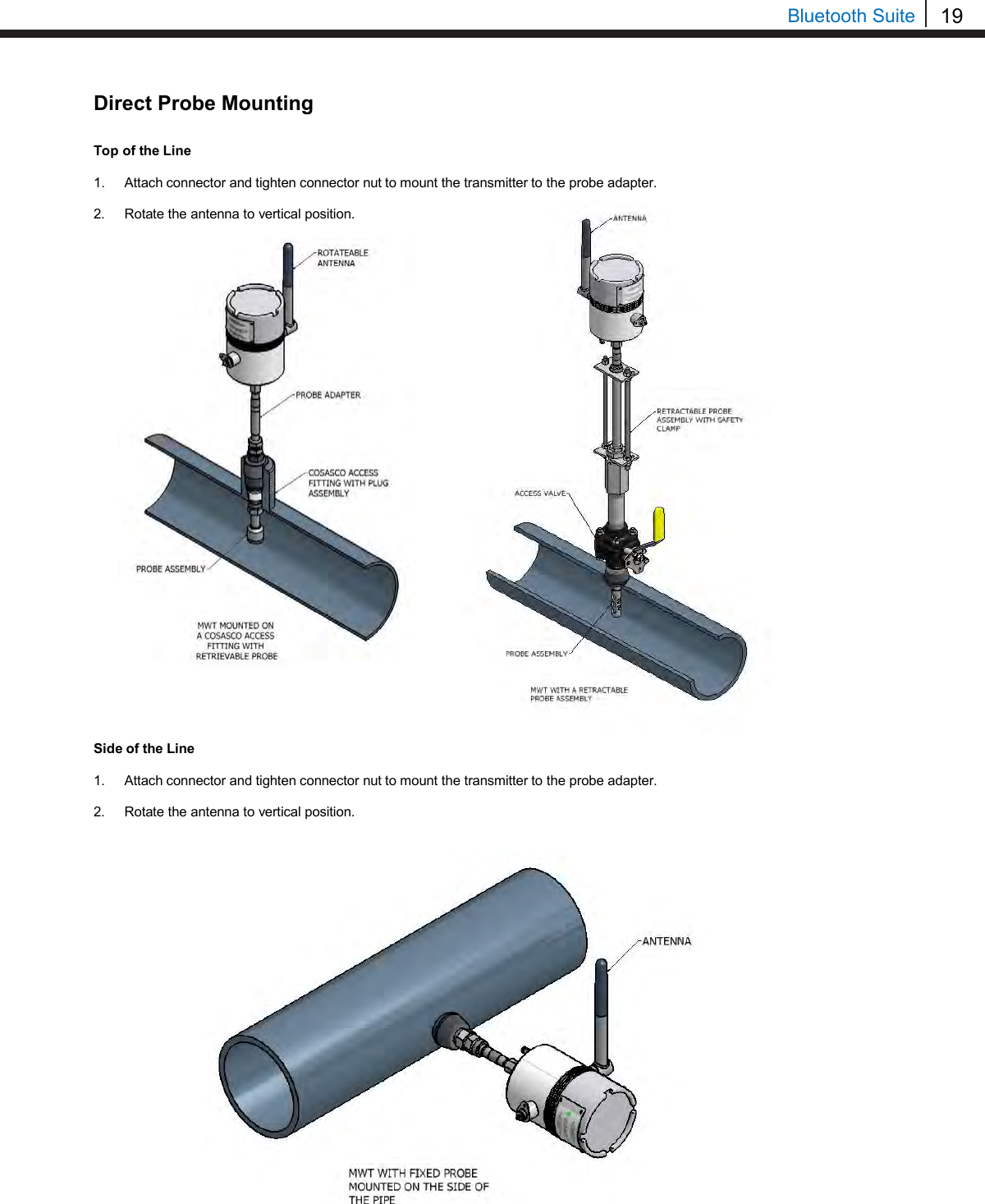
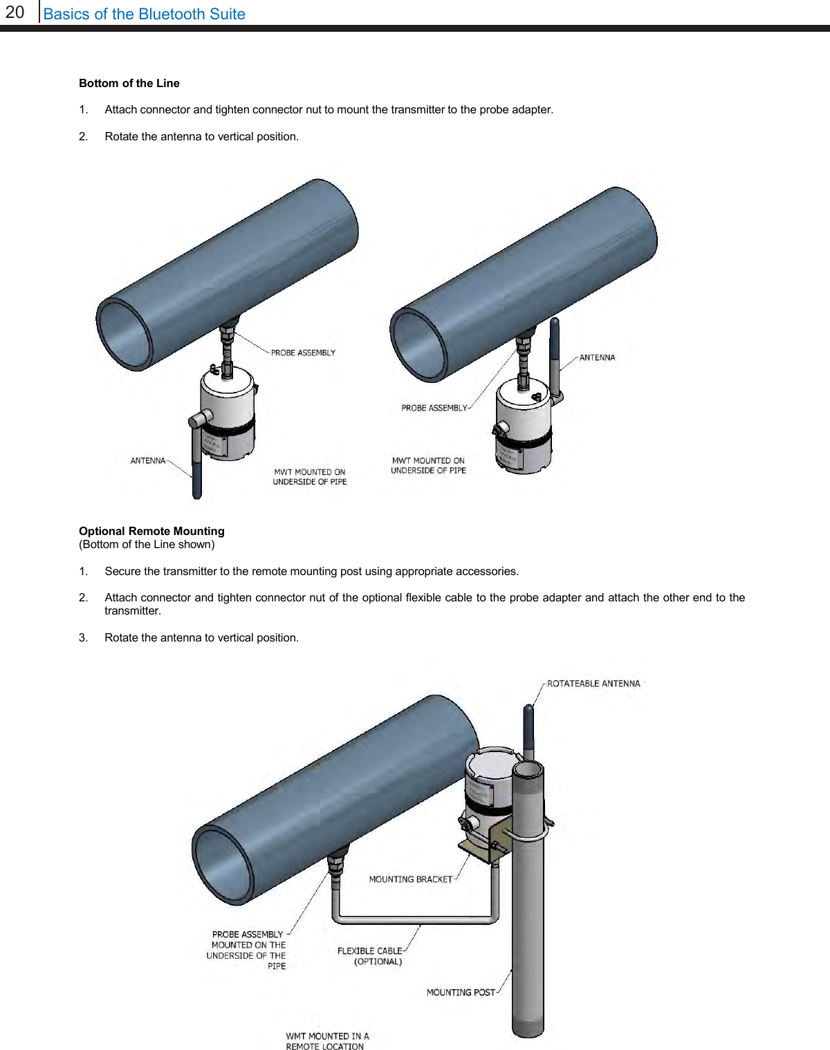
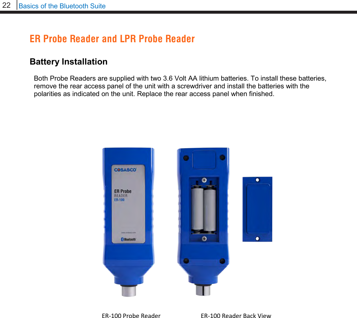
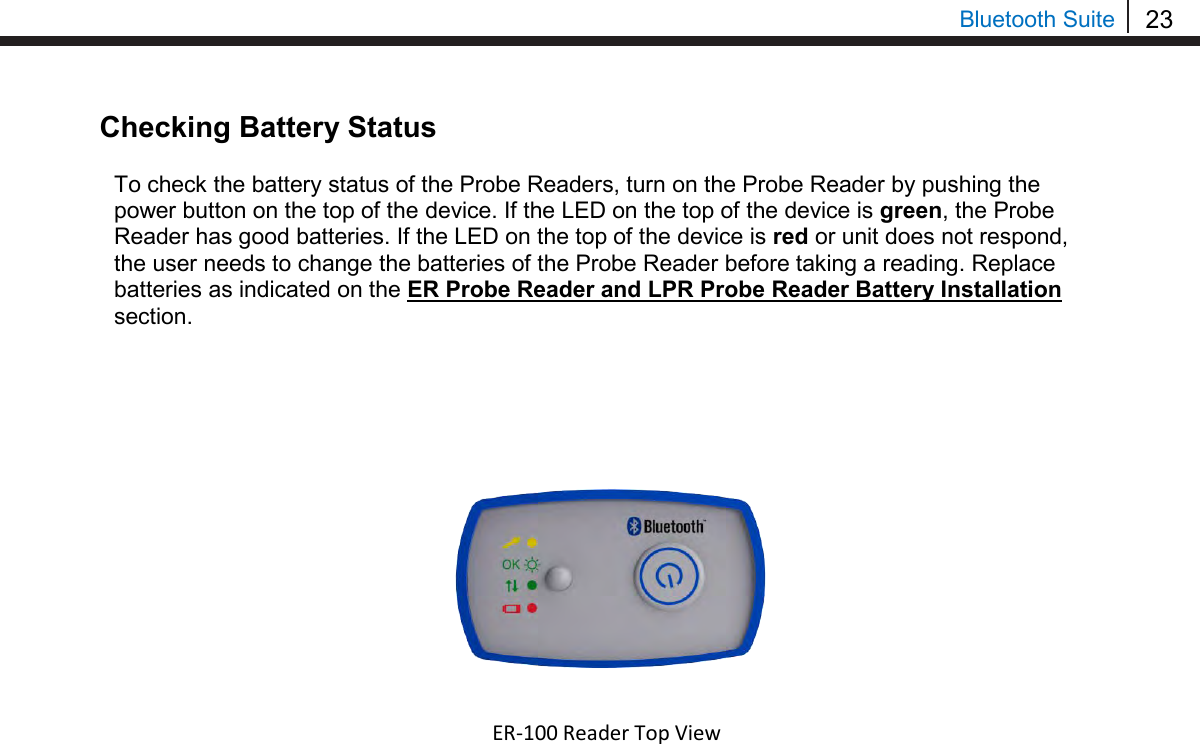
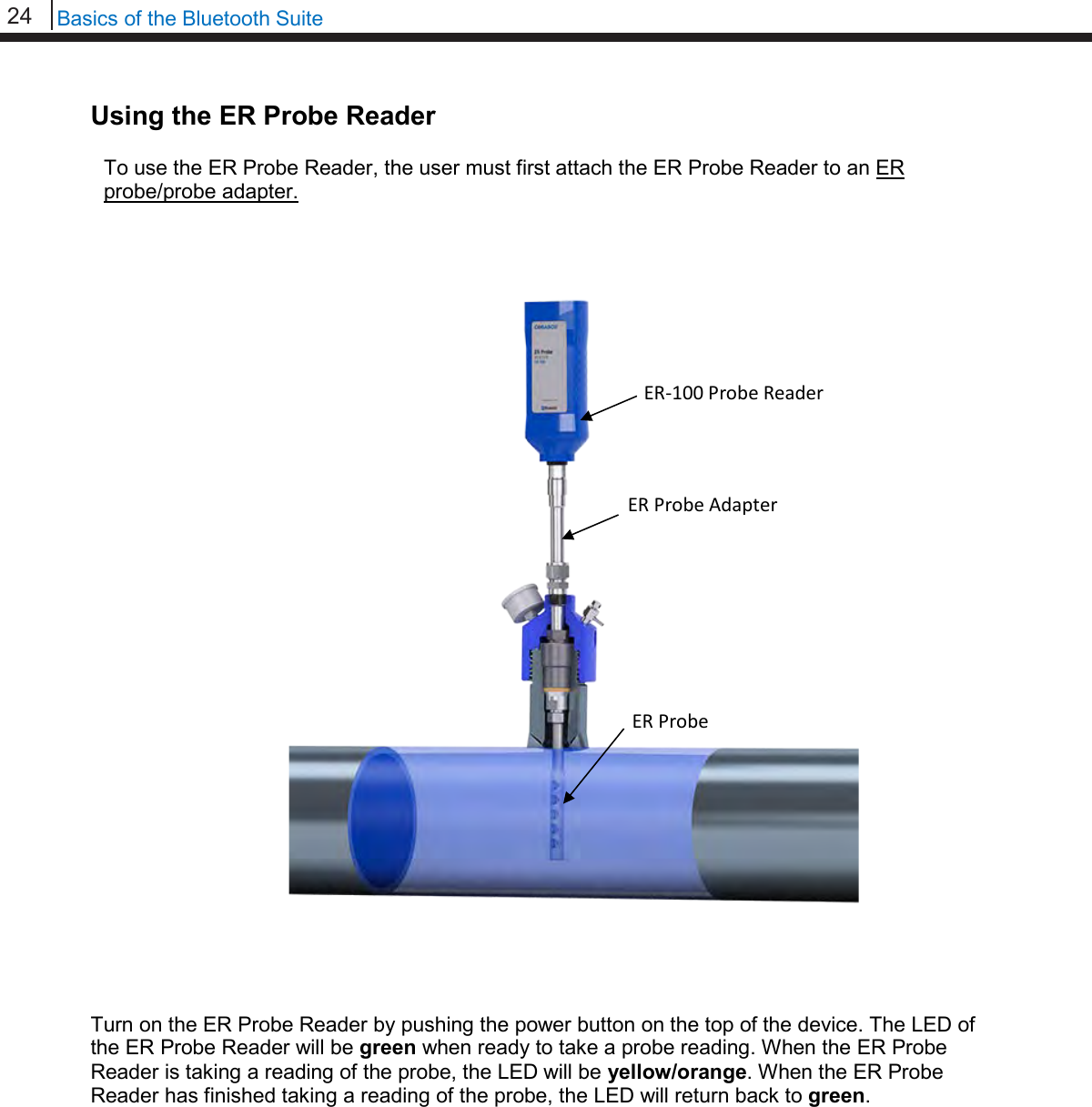
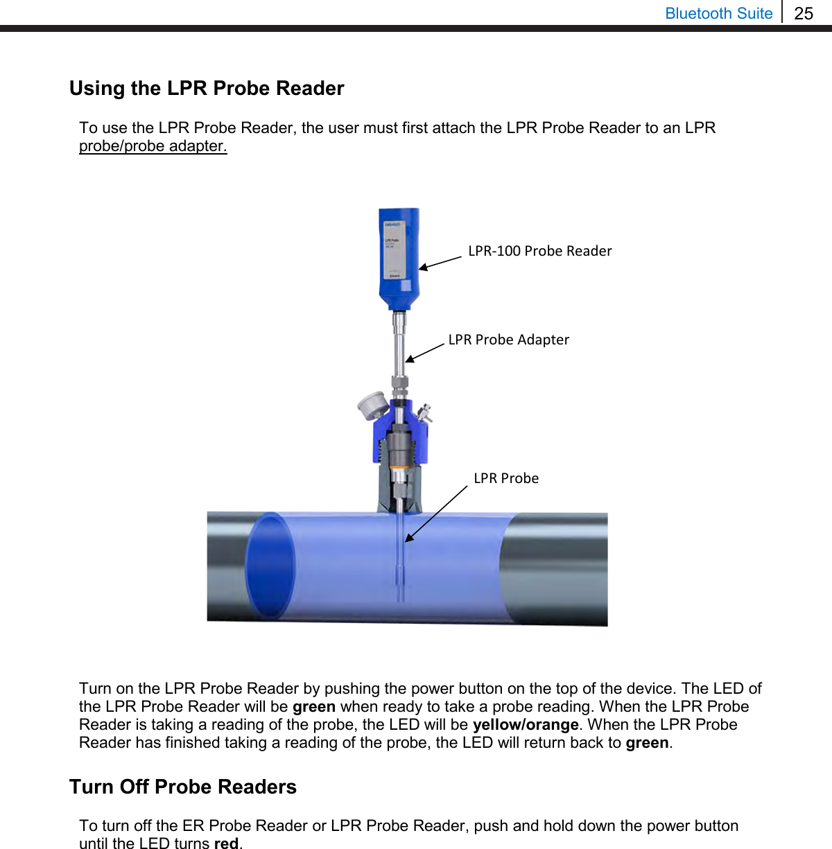
![14 Basics of the Bluetooth Suite Standby Screens The Standby screens are shown below. To navigate between the two standby screens use the More and Back options. Scanning for Devices To scan for devices, select the Scan option on the standby screen. The following screen will appear. Select and amount of time, 10s, 20s, or 30s, to scan for devices. Note: It is recommended to use the 30s scan time to allow for Bluetooth to sync. The Transfer Unit will show the following screens while scanning for devices. When the Transfer Unit has finished scanning, scroll through the list of found devices using the up and down arrows on the keypad. The user can select Sv to save the device to a list. Note: Up to 10 devices can be stored into the saved device list. Select Scan Time 10s | 20s | 30s | Exit Scanning. . . Please Wait XX Found X ►►►►►►►►►►► COSASCO TU-500 vX.XX MM/DD/YY HH:MM:SS Confg | Scan | Device Disp | PC | More COSASCO TU-500 vX.XX MM/DD/YY HH:MM:SS Time | Units | Memory Back | Devices [UP/DOWN] X [XXXXXXXXXX ] Bk=Back Sv=Save Cfg | Dl | St | Bk | Sv](https://usermanual.wiki/Rohrback-Cosasco-Systems/ER200.Users-Manual-1/User-Guide-3661881-Page-20.png)
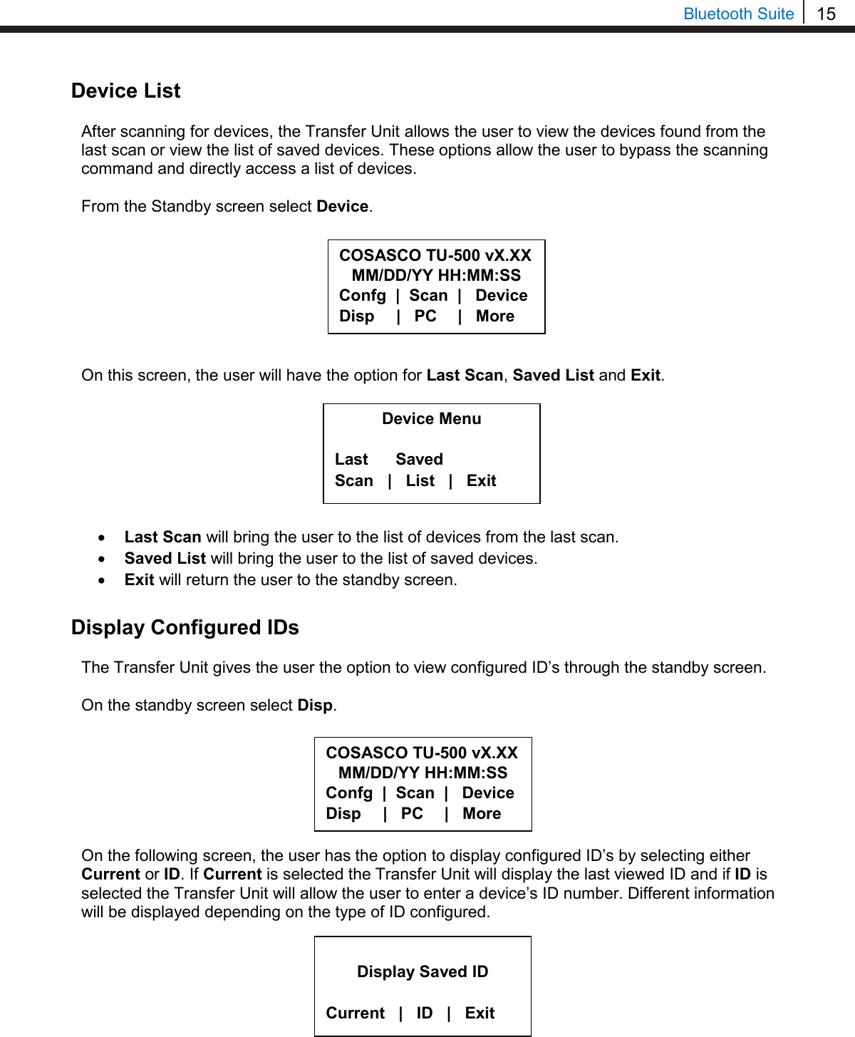
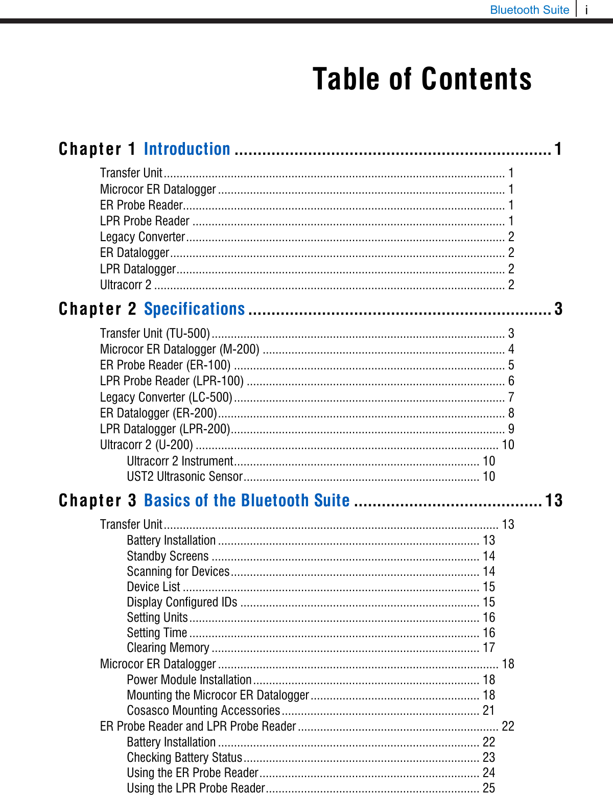
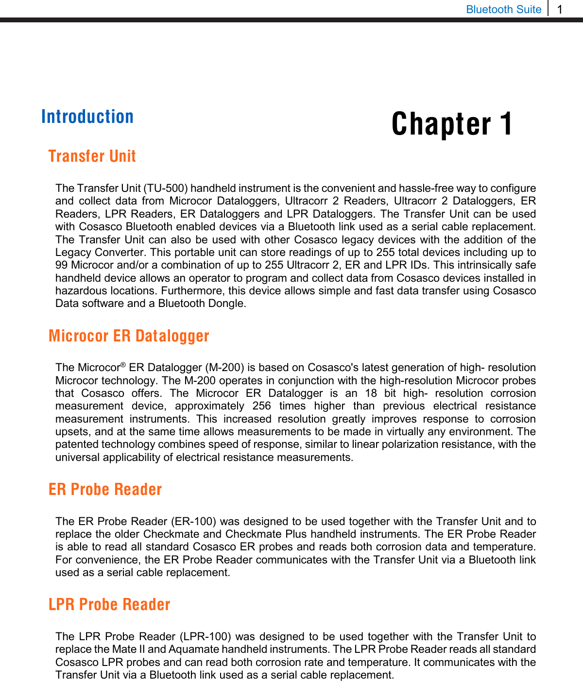
![33 Bluetooth Suite Transfer Unit Microcor ER Datalogger Create an ID for Microcor ER Datalogger On the standby screen of the Transfer Unit select Confg. On the next display screen, select Microcor to get to a list of Microcor devices. Select M-200 for the Microcor ER Datalogger (M-200). Enter the desired ID number then select OK. Enter the interval then select m for minutes. Note: the hours (h) option is disabled and will show INVAL if selected. Microcor M-200 | MDL | ML95 Back | Exit | Select Device ER | LPR | Microcor Ultracorr 2 | Exit Enter ID:[ _ ] (1 – 99) 0123456789.< OK Back Interval:[ _ ] min: (2 – 1440) 0123456789< m h Back Chapter 4](https://usermanual.wiki/Rohrback-Cosasco-Systems/ER200.Users-Manual-1/User-Guide-3661881-Page-39.png)
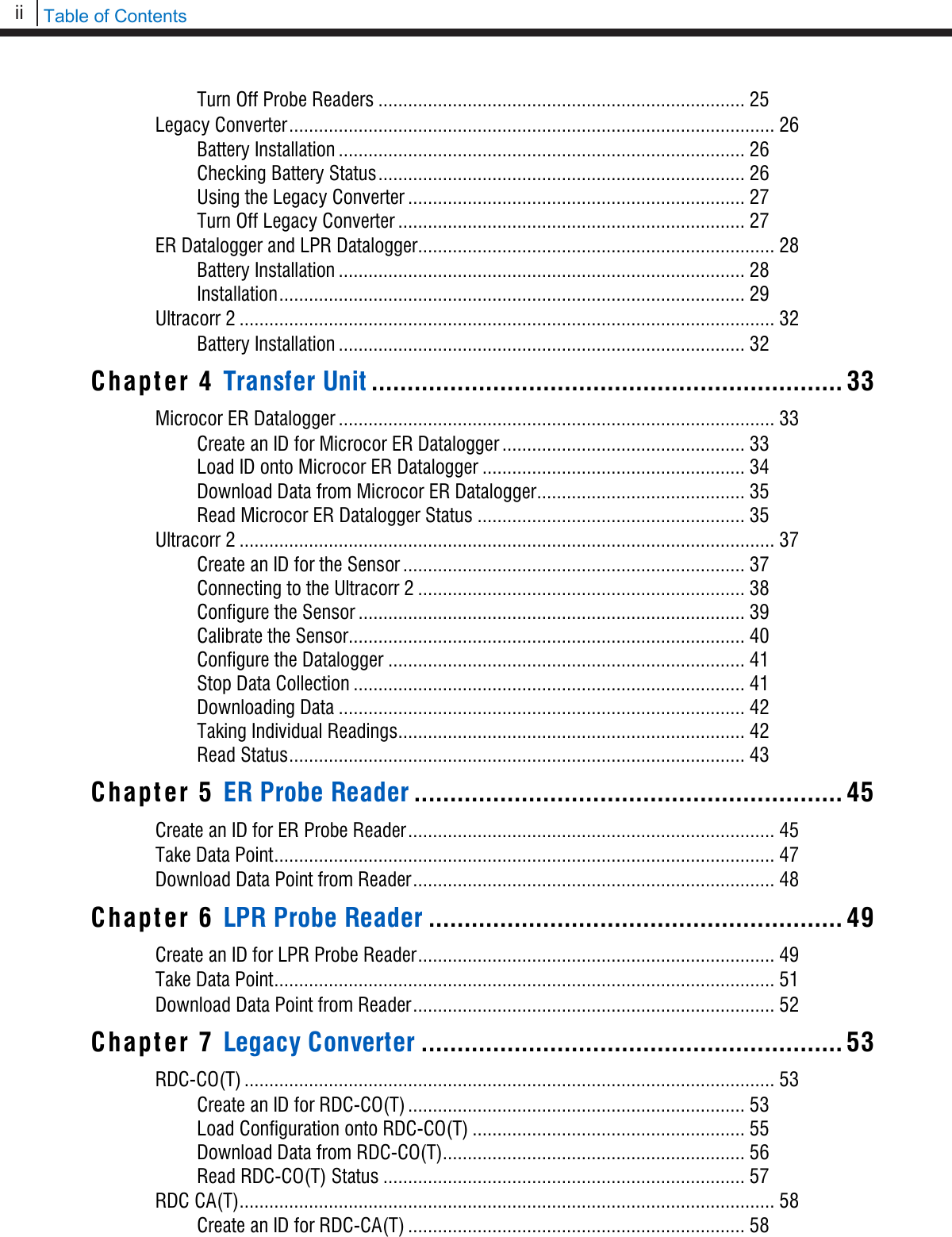
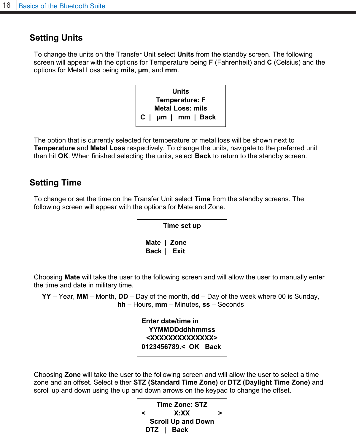
![34 Transfer Unit Enter a tag name for the device then select Nxt. To save the configuration of the device select Okay. Load ID onto Microcor ER Datalogger To load a configuration onto the Microcor ER Datalogger an ID must be created. If the user has not already created an ID, please refer to the Create an ID section. On the Transfer Unit, scroll through the list of Devices until the Bluetooth name of the desired Microcor ER Datalogger device is displayed then select Cfg. Enter the ID of the configuration to load onto the Microcor ER Datalogger then select OK. Select Okay to load the configuration onto the Microcor ER Datalogger. Save? ID: XX TAGNAME Okay | Back | Exit Save? ID: XX TAGNAME Okay | Back | Exit Tag:[ _ ] ABCDEFGHIJKLMNOPQRSTUVWXYZ0123456789._-< Clr | Nxt | Bck | Exit Devices [UP/DOWN] X [XXXXXXXXXX ] Bk=Back Sv=Save Cfg | Dl | St | Bk | Sv Enter ID:[ _ ] (1 – 99) 0123456789.< OK Back](https://usermanual.wiki/Rohrback-Cosasco-Systems/ER200.Users-Manual-1/User-Guide-3661881-Page-40.png)
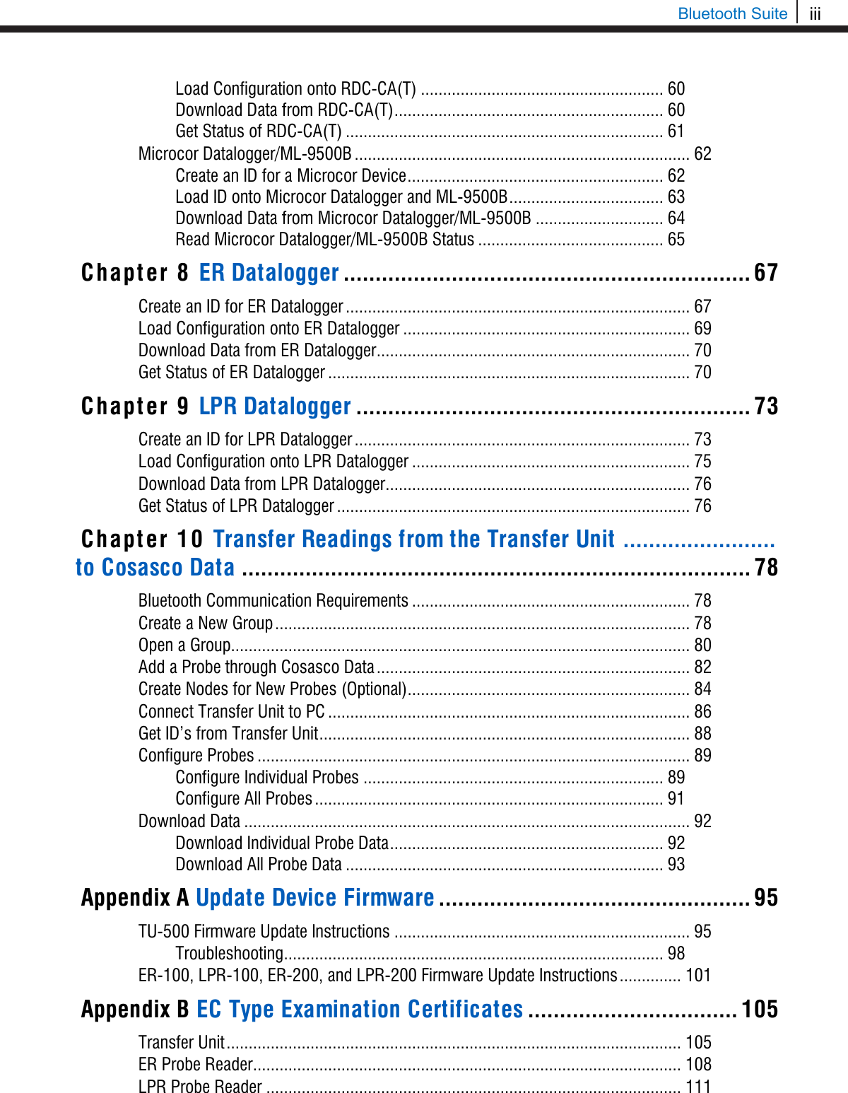
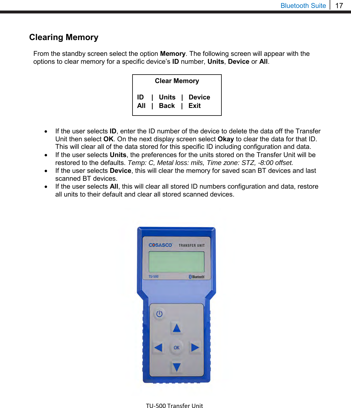
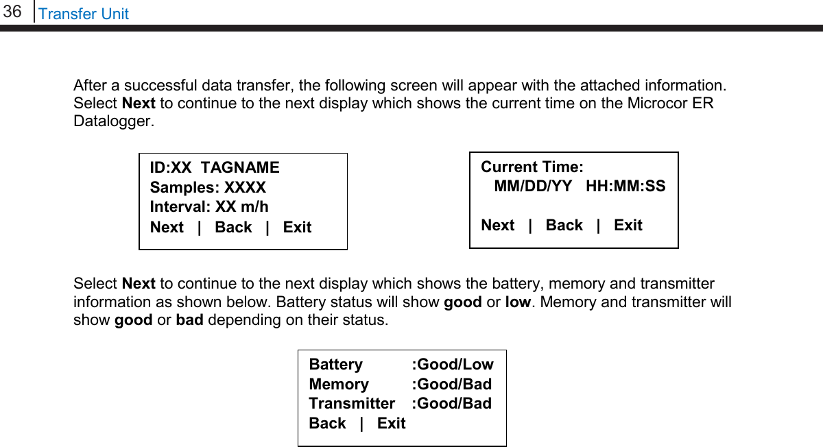
![35 Bluetooth Suite Download Data from Microcor ER Datalogger On the Transfer Unit device list, navigate to the Microcor ER Datalogger device and select Dl. After the transfer of data from the Microcor ER Datalogger to the Transfer Unit is complete, the following screen will display the Microcor ER Datalogger ID number, tag name and the number of samples collected with the interval they are being collected at. Select Next to continue to the next display which shows Probe Life Units (PLU). Select Next to continue to the next display to see the time when the last data point was collected as well as what intervals the data is being taken at. Read Microcor ER Datalogger Status On the Transfer Unit device list, navigate to the Microcor ER Datalogger device and select St. ID:XX M-200 Tag: XXXXXXXX Samples: XXXX (XX m/h) Next | Back | Exit PLU: XXXXX Next | Back | Exit Time Stamp: MM/DD/YY HH:MM:SS Interval: (XX m/h) Back | Exit Devices [UP/DOWN] X [XXXXXXXXXX ] Bk=Back Sv=Save Cfg | Dl | St | Bk | Sv Devices [UP/DOWN] X [XXXXXXXXXX ] Bk=Back Sv=Save Cfg | Dl | St | Bk | Sv](https://usermanual.wiki/Rohrback-Cosasco-Systems/ER200.Users-Manual-1/User-Guide-3661881-Page-41.png)
![37 Bluetooth Suite Ultracorr 2 Create an ID for the Sensor On the standby screen of the Transfer Unit select Confg. On the screen that appears select Ultracorr 2. The user will then have the option to configure the Ultracorr 2 as a Reader or Logger. Choosing Reader will create an ID that can be used when connected to the Ultracorr 2 as a reader. Connecting to the Ultracorr 2 as a reader will allow the user to get readings manually, store the readings and get real-time updates of readings. Choosing Logger will create an ID that can be used when connected to the Ultracorr 2 as a Datalogger. Connecting to the Ultracorr 2 as a Datalogger will allow the user to configure the Ultracorr 2 to read and store data at certain intervals and get real-time updates of readings. After selecting either Reader or Logger, enter the desired ID number then select OK. Enter a tag name for the device then select Nxt. Select Device ER | LPR | Microcor Ultracorr 2 | Exit Ultracorr 2 Reader | Logger Back | Exit Enter ID: [ _ ] (1 – 255) 0123456789.< OK Back Tag:[ _ ] ABCDEFGHIJKLMNOPQRSTUVWXYZ0123456789._-< Clr | Nxt | Bck | Exit](https://usermanual.wiki/Rohrback-Cosasco-Systems/ER200.Users-Manual-1/User-Guide-3661881-Page-43.png)
![38 Transfer Unit Select the correct Alloy. Click Okay to save the configuration for the chosen ID. Connecting to the Ultracorr 2 To connect to the Ultracorr 2 a sensor must be connected to the Ultracorr 2 unit. Access the Ultracorr 2 on the device list of the Transfer Unit and select either Dlgr or Rdr to connect to the Ultracorr 2 as a Datalogger or reader respectively. When successfully connected, the Transfer Unit will display the Ultracorr 2 main menu screen shown below. If the ID shown is 0, the sensor has not been configured. Select Alloy K03005 | S30400 S31600 | Back Save? ID: XX TAGNAME Okay | Back | Exit Ultracorr 2 ver. XX ID: XX TAGNAME Alloy: XXXXXX Sensor | More | Exit Devices [UP/DOWN] X [XXXXXXXX ] Bk=Back Sv=Save Dlgr | Rdr | Bk | Sv](https://usermanual.wiki/Rohrback-Cosasco-Systems/ER200.Users-Manual-1/User-Guide-3661881-Page-44.png)
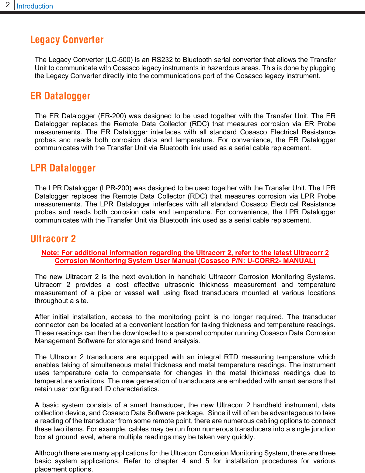
![39 Bluetooth Suite Configure the Sensor To configure the Sensor, first use the Transfer Unit to connect to the Ultracorr 2 device then select Sensor from the Ultracorr 2 main menu screen. The user can either select Save Current to save the current configuration of the sensor to the Transfer Unit or select Confg to load the sensor with the configuration of a specific ID that was created in the Create an ID for the Sensor section. If the user selects Save Current and the same ID number is saved in the Transfer Unit, the following screen will appear. Select Okay to clear the ID found and replace it with the current ID. If the user selects Confg, the following screen will appear. Enter the ID to configure the sensor with. Select Okay to configure the sensor. Ultracorr 2 Sensor Save current | Confg Calibration | Back Clear ID Found? ID: XX TAGNAME Okay | Back | Exit ID: XX TAGNAME Okay | Back | Exit Enter ID: [ _ ] (1 – 255) 0123456789.< OK Back](https://usermanual.wiki/Rohrback-Cosasco-Systems/ER200.Users-Manual-1/User-Guide-3661881-Page-45.png)
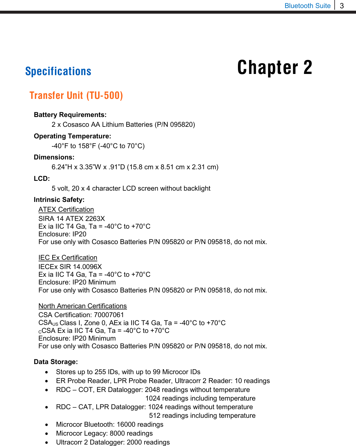
![40 Transfer Unit Calibrate the Sensor WARNING: CALIBRATION IS DONE BY COSASCO AND CHANGES MAY CAUSE INACCURACIES! NOTE: DO NOT attempt to calibrate a transducer without notifying Cosasco. In most cases your transducer will not require a field calibration. If transducer calibration is required, please contact your closest Cosasco regional office location for assistance. Information on the latest software version will be required. To contact Cosasco technical support go to: technicalsupport@cosasco.com or call toll free 1-800-635-6898 Use the Transfer Unit to connect to the Ultracorr 2 device and select Sensor from the Ultracorr 2 main menu screen. On the following screen select Calibration. A warning screen will be displayed stating that Calibration is done by Cosasco and Changes may cause inaccuracies. This screen will disappear after about 3 seconds. Displayed on the next screen are the current values for the Offset, Slope, and Delay. To change these values select Change. The user will then go through the following screens to input the desired values for the Offset, Slope and Delay. Ultracorr 2 Sensor Save current | Confg Calibration | Back WARNING Calib. is done by Cosasco. Changes may cause inaccuracies. Offset: X.XXXX Slope : X.XXXX Delay : X.X Change | Store | Back Offset: [ _ ] 0123456789.< OK Back Slope: < > 0123456789.< OK Back Select Delay 1.0 | 1.5 | 2.0 2.5 | 3.0 | Back](https://usermanual.wiki/Rohrback-Cosasco-Systems/ER200.Users-Manual-1/User-Guide-3661881-Page-46.png)
![41 Bluetooth Suite After the user selects the desired Delay, another warning screen will appear and then a screen will appear with the values selected for Offset, Slope and Delay. These values will not be saved until the user selects Store. Selecting Store will overwrite the current values saved in the Ultracorr 2. Configure the Datalogger This is only available if the Ultracorr 2 is used as a Datalogger when connected to the Transfer Unit. After connecting to the Ultracorr 2 as a Datalogger, select More from the Ultracorr 2 main menu screen and select Confg on the following screen. Enter the desired interval in minutes between 10 and 1440 then select m. Note: The hours (h) option is disabled and will show INVAL if selected. Stop Data Collection This is only available if the Ultracorr 2 is used as a Datalogger when connected to the Transfer Unit. NOTE: Download all data before stopping collection as this will clear the Ultracorr 2’s stored readings! After connecting to the Ultracorr 2 as a Datalogger, select More from the Ultracorr 2 main menu screen and select Stop on the following screen. Ultracorr 2 Logger Confg | Test | Dload Stat | Stop | Back Interval:[ _ ] min: (10 – 1440) 0123456789< m h Back Offset: X.XXXX Slope : X.XXXX Delay : X.X Change | Store | Back Ultracorr 2 Logger Confg | Test | Dload Stat | Stop | Back](https://usermanual.wiki/Rohrback-Cosasco-Systems/ER200.Users-Manual-1/User-Guide-3661881-Page-47.png)
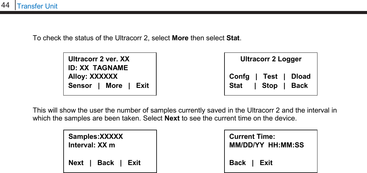
![42 Transfer Unit Downloading Data On the Transfer Unit devices list, navigate to an Ultracorr 2 device and select Dlgr. To download data from the Logger, select More then select Dload. After a successful data transfer, a screen will pop up with information about the last data point collected. Select Next to see the time when the last data point was collected. Taking Individual Readings While connecting to an Ultracorr 2 with the Transfer Unit the user has two options. One option is to get a single reading and be able to save that reading’s data. Another option is to get readings that update continuously. Individual Data Points When connected to the Ultracorr 2 as a Reader the sensor is able to take individual readings and save them. Once connected to the Ultracorr 2, select More from the Ultracorr 2 main menu screen and then select Read. Ultracorr 2 ver. XX ID: XX TAGNAME Alloy: XXXXXX Sensor | More | Exit Ultracorr 2 Reader Read | Test | Back Ultracorr 2 ver. XX ID: XX TAGNAME Alloy: XXXXXX Sensor | More | Exit Ultracorr 2 Logger Confg | Test | Dload Stat | Stop | Back Thickness: X.XXXX in Temp: XX.XX C Gain: XX.XX dB Next | Back | Exit Time stamp: MM/DD/YY HH:MM:SS Back | Exit Devices [UP/DOWN] X [XXXXXXXX ] Bk=Back Sv=Save Dlgr | Rdr | Bk | Sv](https://usermanual.wiki/Rohrback-Cosasco-Systems/ER200.Users-Manual-1/User-Guide-3661881-Page-48.png)
![43 Bluetooth Suite After a successful reading, a screen displaying Thickness, Temperature, Gain and Battery Voltage values will appear. To get another reading select Read. To save the reading select Save. To Exit this screen, select Back. Real-Time Data When connected to the Ultracorr 2 as a Reader or Datalogger, the user is able to take readings that update in real-time. Once connected to the Ultracorr 2, select More from the Ultracorr 2 main menu screen and then select Test After a successful read, a screen displaying Thickness, Temperature, Gain and Battery Voltage values will appear and continuously update with new data. When the user wants to exit this screen, hold OK. Note: A Battery Voltage reading below 4.5V means that the batteries are low and need to be replaced. Read Status On the Transfer Unit devices list screen, navigate to an Ultracorr 2 device and select Dlgr. Ultracorr 2 ver. XX ID: XX TAGNAME Alloy: XXXXXX Sensor | More | Exit Ultracorr 2 Reader Read | Test | Back Thickness: X.XXXX in Temp: XX.XX C | Hold Gain: XX.XX dB | OK to Batt: X.XX V | ►Exit Thickness: X.XXXX in Temp: XX.XX C | Read Gain: XX.XX dB | Save Batt: X.XX V | Back Ultracorr 2 Logger Confg | Test | Dload Stat | Stop | Back Devices [UP/DOWN] X [XXXXXXXX ] Bk=Back Sv=Save Dlgr | Rdr | Bk | Sv](https://usermanual.wiki/Rohrback-Cosasco-Systems/ER200.Users-Manual-1/User-Guide-3661881-Page-49.png)
![45 Bluetooth Suite Chapter 5 ER Probe Reader The Transfer Unit is used with the ER Probe Reader to utilize all of the ER Probe Reader functions. Refer to Basics of the Bluetooth Suite – ER Probe Reader and LPR Probe Reader for more information on how to use the ER Probe Reader. Create an ID for ER Probe Reader On the Transfer Unit standby screen select Confg. On the next display screen, select ER to get to a list of ER devices. Select Reader from the list of devices. Enter the desired ID number then select OK. Enter a tag name for the device then select Nxt. Select Device ER | LPR | Microcor Ultracorr 2 | Exit ER Reader | Logr | RDC Back | Exit | Enter ID: [ _ ] (1 – 255) 0123456789.< OK Back Tag:[ _ ] ABCDEFGHIJKLMNOPQRSTUVWXYZ0123456789._-< Clr | Nxt | Bck | Exit](https://usermanual.wiki/Rohrback-Cosasco-Systems/ER200.Users-Manual-1/User-Guide-3661881-Page-51.png)
![46 ER Probe Reader Enter in the name of the alloy then select Nxt. Note: The name of the alloy is for reference only and does not affect the calculation of corrosion rates. Select the probe type used with the Reader then select Next. If the user selects any of the Other probe options, the following screen will appear. Manually enter the span of the probe. Select if the probe is a temperature probe or not by selecting either Yes or No. To save the ID select Okay. Save? ID: XXX TAGNAME Okay | Back | Exit Alloy: [ _ ] ABCDEFGHIJKLMNOPQR STUVWXYZ0123456789._-< Clr | Nxt | Bck | Exit Select Probe Type [XX XXXXXXXXXXXX X] Scroll up and down Next | Back | Exit Is it a Temp. Probe? Yes | No | Bck | Exit Span:< _ > mils 0123456789.< OK Back](https://usermanual.wiki/Rohrback-Cosasco-Systems/ER200.Users-Manual-1/User-Guide-3661881-Page-52.png)
![47 Bluetooth Suite Take Data Point On the Transfer Unit device list screen, navigate to the ER Probe Reader and select Read. The user will have the option to either select ID or Quick to read the probe connected to the Reader. • If ID is selected, the user will need to enter an ID preconfigured for the ER Probe Reader to take the data of and select OK. On the confirmation screen select Okay and the reader will begin to read the probe. Note: If the user has not already created an ID, please refer to the Create an ID for Reader section for the ER Probe Reader. • If Quick is selected, the user will need to manually enter the probe type, the span of the probe, and if the probe is a temperature probe or not. Once one of the previous steps is completed, the ER Probe Reader will take a reading of the attached probe. The ER Probe Reader has finished taking a reading once the ER Probe Reader light goes from yellow/orange back to blinking green. Enter ID: [ _ ] (1-255) 0123456789.< OK Back ID: XXX TAGNAME Okay | Back | Exit Select Probe Type A | B | C | D G | u | Back | Exit Span: < > mils 0123456789.< OK Back Is it a Temp. Probe? Yes | No | Bck | Exit Devices [UP/DOWN] X [XXXXXXXXXX ] Bk=Back Cl=Clear Read | Dl | Bk | Cl](https://usermanual.wiki/Rohrback-Cosasco-Systems/ER200.Users-Manual-1/User-Guide-3661881-Page-53.png)
![48 ER Probe Reader Download Data Point from Reader Before Downloading Data from the Reader, the user must first take a reading from the Reader. If this has not been done, please refer to the Take Data Point section. Once the user finds an ER Probe Reader to download data from on the Transfer Unit select Dl. After the transfer of the data point from the Reader to the Transfer Unit is complete, a screen will display information about the data on the Reader including the Divisions and Check Readings, Temperature, Metal Loss and the time that the last data point was collected from the device. To save the current data to the Transfer Unit select Save. Note: This option will only be available if the user read from the Reader using a pre-configured ID. Div: XXX.X Chk: XXX.X Temp: XXXX.X C MLoss: X.XXX mils Next | Back | Exit Time Stamp: MM/DD/YY HH:MM:SS Save | Back | Exit Devices [UP/DOWN] X [XXXXXXXXXX ] Bk=Back Cl=Clear Read | Dl | Bk | Cl](https://usermanual.wiki/Rohrback-Cosasco-Systems/ER200.Users-Manual-1/User-Guide-3661881-Page-54.png)
![49 Bluetooth Suite LPR Probe Reader The Transfer Unit is used with the LPR Probe Reader to utilize all of the LPR Probe Reader functions. Refer to Basics of the Bluetooth Suite – ER Probe Reader and LPR Probe Reader for more information on how to use the LPR Probe Reader. Create an ID for LPR Probe Reader On the Transfer Unit standby screen select Confg. On the next display screen, select LPR to get to a list of LPR devices. Select Reader from the list of devices. Enter the desired ID number then select OK. Enter a tag name for the device then select Nxt. Chapter 6 Select Device ER | LPR | Microcor Ultracorr 2 | Exit Enter ID:[ _ ] (1 – 255) 0123456789.< OK Back Tag:[ _ ] ABCDEFGHIJKLMNOPQRSTUVWXYZ0123456789._-< Clr | Nxt | Bck | Exit LPR Reader | RDC2 | RDC Back | Exit |](https://usermanual.wiki/Rohrback-Cosasco-Systems/ER200.Users-Manual-1/User-Guide-3661881-Page-55.png)
![50 LPR Probe Reader Select an alloy by using the up and down arrows to scroll through the choices then select Next. If Other is selected, the name of the alloy and the multiplier (mult) will have to be inputted manually. Select either Stdrd-E or Flush-F for the probe type. Select the cycle time in minutes for the device by selecting either 5, 10, 15 or 20. Select if the probe is a temperature probe or not by selecting either Yes or No. To save the configuration of the device select Okay. Alloy: [ _ ] ABCDEFGHIJKLMNOPQR STUVWXYZ0123456789._-< Clr | Nxt | Bck | Exit Mult:< > 0123456789.< OK Back Save? ID: XXX TAGNAME Okay | Back | Exit Select Alloy XXXXXXXXXXXXX XXXXXX (scroll U/D) Next | Back | Exit Select Probe Type Stdrd-E | Flush-F Back | Exit Select Cycle Time in Minutes 5 | 10 | 15 | 20 | Back Is it a Temp. Probe? Yes | No | Bck | Exit](https://usermanual.wiki/Rohrback-Cosasco-Systems/ER200.Users-Manual-1/User-Guide-3661881-Page-56.png)
![51 Bluetooth Suite Take Data Point On the Transfer Unit device list screen, navigate to the LPR Probe Reader and select Read. The user will have the option to either select ID or Quick to read the probe connected to the Reader. • If ID is selected, the user will need to enter an ID preconfigured for the LPR Probe Reader to take the data of and select OK. On the confirmation screen select Okay and the reader will begin to read the probe. Note: If the user has not already created an ID, please refer to the Create an ID for Reader section for the LPR Probe Reader. • If Quick is selected, the user will need to manually select the alloy, the type of probe, the cycle time in minutes and if the probe is a temperature probe or not. Once one of the previous steps is completed, the LPR Probe Reader will take a reading of the attached probe. The LPR Probe Reader has finished taking a reading once the LPR Probe Reader light goes from yellow/orange back to blinking green. Enter ID: [ _ ] (1-255) 0123456789.< OK Back ID: XXX TAGNAME Okay | Back | Exit Is it a Temp. Probe? Yes | No | Bck | Exit Select Alloy XXXXXXXXXXXXX XXXXXX (scroll u/d) Next | Back | Exit Select Probe Type Stdrd-E | Flush-F Back | Exit Select Cycle Time in Minutes 5 | 10 | 15 | 20 | Back Devices [UP/DOWN] X [XXXXXXXXXX ] Bk=Back Cl=Clear Read | Dl | Bk | Cl](https://usermanual.wiki/Rohrback-Cosasco-Systems/ER200.Users-Manual-1/User-Guide-3661881-Page-57.png)
![52 LPR Probe Reader Download Data Point from Reader Before Downloading Data from the Reader, the user must first take a reading from the Reader. If this has not been done, please refer to the Take Data Point section. On the Transfer Unit devices list screen, navigate to the LPR Probe Reader then select Dl. After a successful data transfer, a screen will display information about the data in the Reader including the Rate, Imbalance, Temperature and the time that the last data point was collected from the device. To save the current data to the Transfer Unit select Save. Note: This option will only be available if the user read from the Reader using a pre-configured ID. Time Stamp: MM/DD/YY HH:MM:SS Save | Back | Exit Rate: XXX mpy Imb: XX.XXX Temp: XXX Next | Back | Exit Devices [UP/DOWN] X [XXXXXXXXXX ] Bk=Back Cl=Clear Read | Dl | Bk | Cl](https://usermanual.wiki/Rohrback-Cosasco-Systems/ER200.Users-Manual-1/User-Guide-3661881-Page-58.png)
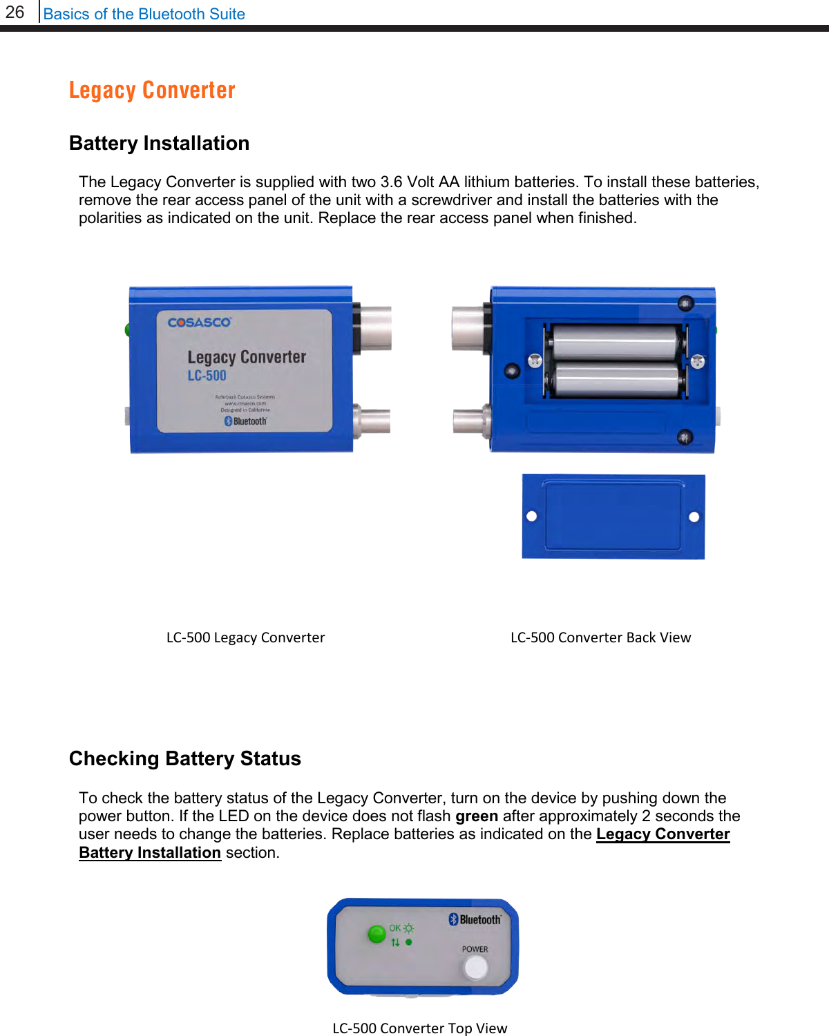
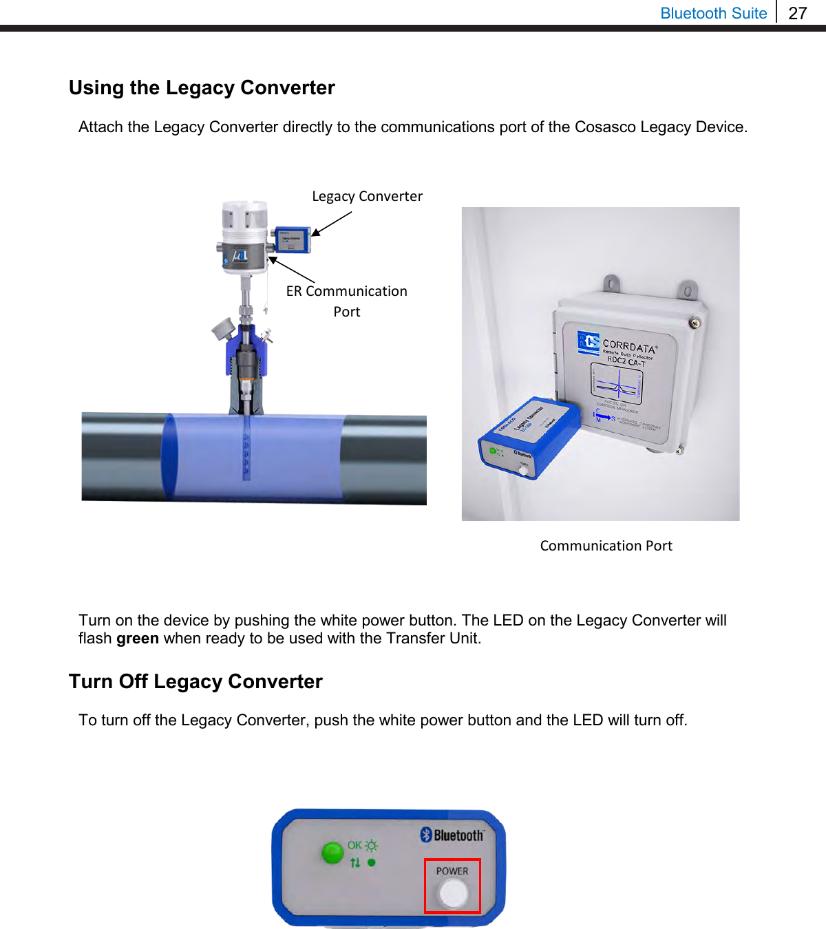
![53 Bluetooth Suite Chapter 7 Legacy Converter The Transfer Unit is used with the Legacy Converter to utilize all of the Legacy Converter functions. Refer to Basics of the Bluetooth Suite – Legacy Converter for more information on how to use the Legacy Converter. RDC-CO(T) To use the Transfer Unit with the RDC-CO(T), a Legacy Converter must be connected to the RDC-CO(T)’s service port to allow for communication between devices. Create an ID for RDC-CO(T) On the Transfer Unit standby screen select Confg. On the next display screen, select ER to get to a list of Corrosometer devices. Select RDC from the list of devices. Enter the desired ID number then select OK. Select Device ER | LPR | Microcor Ultracorr 2 | Exit ER Reader | Logr | RDC Back | Exit | Enter ID: [ _ ] (1 – 255) 0123456789.< OK Back](https://usermanual.wiki/Rohrback-Cosasco-Systems/ER200.Users-Manual-1/User-Guide-3661881-Page-59.png)
![54 Legacy Converter Enter the interval then select m for minutes or h for hours. Enter a tag name for the device then select Nxt. Enter in the name of the alloy then select Nxt. Note: The name of the alloy is for reference only and does not affect the calculation of corrosion rates. Select the probe type used with the RDC-CO(T) then select Next. If the user selects any of the Other probe options, the following screen will appear. Manually enter the span of the probe. Select if the probe is a temperature probe or not by selecting either Yes or No. Interval: [ _ ] min:(5-30) hr:(1-24) 0123456789< m h Back Tag:[ _ ] ABCDEFGHIJKLMNOPQRSTUVWXYZ0123456789._-< Clr | Nxt | Bck | Exit Alloy: [ _ ] ABCDEFGHIJKLMNOPQR STUVWXYZ0123456789._-< Clr | Nxt | Bck | Exit Select Probe Type < XX XXXXXXXXX X > Scroll up and down Next | Back | Exit Is it a Temp. Probe? Yes | No | Bck | Exit Span:< > mils 0123456789.< OK Back](https://usermanual.wiki/Rohrback-Cosasco-Systems/ER200.Users-Manual-1/User-Guide-3661881-Page-60.png)
![55 Bluetooth Suite To save the configuration of the device select Okay. Load Configuration onto RDC-CO(T) To load a configuration onto the RDC-CO(T) an ID must be created. If the user has not already created an ID, please refer to the Create an ID for RDC-CO(T) section. On the device list screen, find the Legacy Converter device by pushing the up and down keys and select Cfg. On the following screen, select RDC-COT. Enter the ID of the configuration to load onto the RDC-CO(T) then select OK. On the following screen, select Okay to load the configuration onto the RDC-CO(T). Save? ID: XXX TAGNAME Okay | Back | Exit Select Device RDC-COT | MDL/ML9500 RDC-CAT | Back | Exit Enter ID:[ _ ] (1 – 99) 0123456789.< OK Back ID: XX TAGNAME Okay | Back | Exit Devices [UP/DOWN] X [XXXXXXXXXX ] Bk=Back Sv=Save Cfg | Dl | St | Bk | Sv](https://usermanual.wiki/Rohrback-Cosasco-Systems/ER200.Users-Manual-1/User-Guide-3661881-Page-61.png)
![56 Legacy Converter Download Data from RDC-CO(T) On the Transfer Unit device list screen, navigate to the Legacy Converter device connected to the RDC-CO(T) to download the data from and select DL. On the following screen, select RDC-COT. After successful data transfer, a screen will display information about the RDC-CO(T) and the latest reading. Use Next to navigate between the screens and see the Alloy, Span, Divisions and Check Readings, Temperature, Metal Loss and the time that the last data point was collected from the device. ID: XXX (X) RDC-COT Tag: XXXXXXX Samples XXX ( XX m/h) Next | Back | Exit Alloy: XX Span: XX.XXX mils Next | Back | Exit Div: XXX.X Chk: XXX.X Temp: XXXX.X C MLoss: X.XXX mils Next | Back | Exit Time Stamp: MM/DD/YY HH:MM:SS Interval: XX m/h Back | Exit Select Device RDC-COT | MDL/ML9500 RDC-CAT | Back | Exit Devices [UP/DOWN] X [XXXXXXXXXX ] Bk=Back Sv=Save Cfg | Dl | St | Bk | Sv](https://usermanual.wiki/Rohrback-Cosasco-Systems/ER200.Users-Manual-1/User-Guide-3661881-Page-62.png)
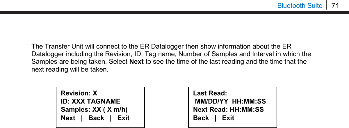
![57 Bluetooth Suite Read RDC-CO(T) Status On the Transfer Unit device list screen, navigate to the Legacy Converter device connected to the RDC and select St. On the following screen, select RDC-COT. The Transfer Unit will connect to the RDC-CO(T) then show information about the RDC-CO(T) including the Revision, ID, Tag name, Number of Samples and Interval in which the Samples are being taken. Select Next to see the time of the last reading and the time that the next reading will be taken. Select Device RDC-COT | MDL/ML9500 RDC-CAT | Back | Exit Revision: X ID: XXX TAGNAME Samples: XX ( X m/h) Next | Back | Exit Last Read: MM/DD/YY HH:MM:SS Next Read: HH:MM:SS Back | Exit Devices [UP/DOWN] X [XXXXXXXXXX ] Bk=Back Sv=Save Cfg | Dl | St | Bk | Sv](https://usermanual.wiki/Rohrback-Cosasco-Systems/ER200.Users-Manual-1/User-Guide-3661881-Page-63.png)
![58 Legacy Converter RDC CA(T) To use the Transfer Unit with the RDC-CA(T), a Legacy Converter must be connected to the RDC-CA(T)’s service port to allow for communication between devices. Create an ID for RDC-CA(T) On the Transfer Unit standby screen select Confg. On the next display screen, select LPR to get to a list of Corrater devices. Select RDC from the list of devices. Enter the desired ID number then select OK. Enter the interval then select m for minutes or h for hours. Enter a tag name for the device then select Nxt. Select Device ER | LPR | Microcor Ultracorr 2 | Exit LPR Reader | Logr | RDC Back | Exit | Interval: [ _ ] min:(30) hr:(1-24) 0123456789< m h Back Tag:[ _ ] ABCDEFGHIJKLMNOPQRSTUVWXYZ0123456789._-< Clr | Nxt | Bck | Exit Enter ID: [ _ ] (1 – 255) 0123456789.< OK Back](https://usermanual.wiki/Rohrback-Cosasco-Systems/ER200.Users-Manual-1/User-Guide-3661881-Page-64.png)
![59 Bluetooth Suite Select an alloy by using the up and down arrows to scroll through the choices then select Next. If Other is selected, the name of the alloy and the multiplier (mult) will have to be inputted manually. Select either Stdrd-E or Flush-F for the probe type. Select if the probe is a temperature probe or not by selecting either Yes or No. To save the configuration of the device select Okay. Alloy: [ _ ] ABCDEFGHIJKLMNOPQR STUVWXYZ0123456789._-< Clr | Nxt | Bck | Exit Mult:< > 0123456789.< OK Back Save? ID: XXX TAGNAME Okay | Back | Exit Is it a Temp. Probe? Yes | No | Bck | Exit Select Alloy XXXXXXXXXXXXX XXXXXX (scroll U/D) Next | Back | Exit Select Probe Type Stdrd-E | Flush-F Back | Exit](https://usermanual.wiki/Rohrback-Cosasco-Systems/ER200.Users-Manual-1/User-Guide-3661881-Page-65.png)
![60 Legacy Converter Load Configuration onto RDC-CA(T) To load a configuration onto the RDC-CA(T) an ID must be created. If the user has not already created an ID, please refer to the Create an ID for RDC-CA(T) section. On the Transfer Unit device list screen, find the Legacy Converter connected to the RDC-CA(T) and select Cfg. On the following screen, select RDC-CAT. Enter the ID of the configuration to load onto the RDC-CA(T) then select OK. On the following screen, select Okay to load the configuration onto the RDC-CA(T). Download Data from RDC-CA(T) On the Transfer Unit devices list screen, navigate to the Legacy Converter device connected to the RDC-CA(T) and select Dl. Select Device RDC-COT | MDL/ML9500 RDC-CAT | Back | Exit ID: XX TAGNAME Okay | Back | Exit Devices [UP/DOWN] X [XXXXXXXXXX ] Bk=Back Sv=Save Cfg | Dl | St | Bk | Sv Enter ID:[ _ ] (1 – 99) 0123456789.< OK Back Devices [UP/DOWN] X [XXXXXXXXXX ] Bk=Back Sv=Save Cfg | Dl | St | Bk | Sv](https://usermanual.wiki/Rohrback-Cosasco-Systems/ER200.Users-Manual-1/User-Guide-3661881-Page-66.png)
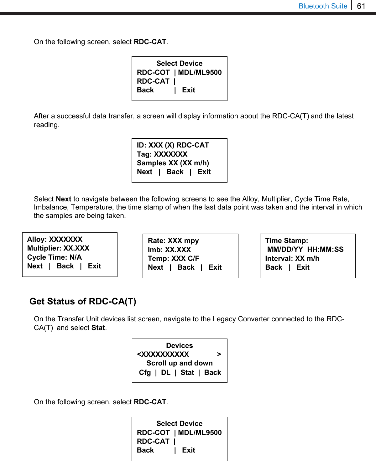
![62 Legacy Converter Once the Transfer Unit has connected to the RDC-CA(T) it will show a screen with the Revision, ID, Tag Name, Number of Samples collected and the interval in which the samples are taken for the RDC. Select Next to see when the last reading was taken and when the next reading will be taken. Microcor Datalogger/ML-9500B To use the Transfer Unit with the Microcor Datalogger/ML-9500B, a Legacy Converter must be connected to the Microcor Datalogger/ML-9500B serial port to allow for communication between devices. Create an ID for a Microcor Device On the Transfer Unit standby screen select Confg. On the next display screen, select uCor to get to a list of Microcor devices. Select the type of Microcor Device. • MDL (Microcor Datalogger) – MWT-3905-MDL • ML95 (Legacy Microcor Datalogger) – ML-9500B Enter the desired ID number then select OK. Revision: X ID: XXX TAGNAME Samples XX ( X m/h) Next | Back | Exit Last Read: MM/DD/YY HH:MM:SS Next read: HH:MM:SS Back | Exit Microcor M-200 | MDL | ML95 Back | Exit | Select Device ER | LPR | Microcor Ultracorr 2 | Exit Enter ID:[ _ ] (1 – 99) 0123456789.< OK Back](https://usermanual.wiki/Rohrback-Cosasco-Systems/ER200.Users-Manual-1/User-Guide-3661881-Page-68.png)
![63 Bluetooth Suite Enter the interval then select m for minutes. Note: the hours (h) option is disabled and will show INVAL if selected. Enter a tag name for the device then select Nxt. To save the configuration of the device select Okay. Load ID onto Microcor Datalogger and ML-9500B To load a configuration onto the MDL/ML9500 a configuration must be created. If the user has not already created a configuration, please refer to the Create an ID for a Microcor Device section. Scroll through the list of devices on the Transfer Unit until the Bluetooth name of the desired Legacy Converter is displayed and then select Cfg. On the following screen, select MDL/ML9500. Save? ID: XX TAGNAME Okay | Back | Exit Interval:[ _ ] min: (5 – 1440) 0123456789< m h Back Tag:[ _ ] ABCDEFGHIJKLMNOPQRSTUVWXYZ0123456789._-< Clr | Nxt | Bck | Exit Select Device RDC-COT | MDL/ML9500 RDC-CAT | Back | Exit Devices [UP/DOWN] X [XXXXXXXXXX ] Bk=Back Sv=Save Cfg | Dl | St | Bk | Sv](https://usermanual.wiki/Rohrback-Cosasco-Systems/ER200.Users-Manual-1/User-Guide-3661881-Page-69.png)
![64 Legacy Converter Enter the ID of the configuration to load onto the Datalogger then select OK. On the following screen, select Okay to load the configuration onto the Datalogger. Download Data from Microcor Datalogger/ML-9500B On the Transfer Unit device list, navigate to the Legacy Converter connected to the Microcor Datalogger or ML-9500B and select Dl. On the following screen, select MDL/ML9500. After a successful data transfer, a screen will appear with information about the MDL/ML-9500B including its ID, Tag Name, the number of samples downloaded and the interval in which data is collected. Select Device RDC-COT | MDL/ML9500 RDC-CAT | Back | Exit ID:XX MDL Tag: TAGNAME Samples: XXXX (XX m) Next | Back | Exit Devices [UP/DOWN] X [XXXXXXXXXX ] Bk=Back Sv=Save Cfg | Dl | St | Bk | Sv ID: XX TAGNAME Okay | Back | Exit Enter ID:[ _ ] (1 – 99) 0123456789.< OK Back ID:XX ML9500 Tag: TAGNAME Samples: XXXX (XX m) Next | Back | Exit](https://usermanual.wiki/Rohrback-Cosasco-Systems/ER200.Users-Manual-1/User-Guide-3661881-Page-70.png)
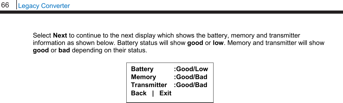
![65 Bluetooth Suite Select Next to continue to the next display which shows Probe Life Units (PLU). Select Next to continue to the next display to see the time when the last data point was collected as well as what intervals the data is being taken at. Read Microcor Datalogger/ML-9500B Status On the Transfer Unit device list, navigate to the Legacy Converter device connected to the Microcor Datalogger or ML-9500B and select St. On the following screen, select MDL/ML9500. After a successful data transfer, the following screen will appear with the attached information. Select Next to continue to the next display which shows the current time on the MDL. PLU: XXXXX Next | Back | Exit Time Stamp: MM/DD/YY HH:MM:SS Interval: (XX m) Back | Exit Select Device RDC-COT | MDL/ML9500 RDC-CAT | Back | Exit ID:XX TAGNAME Samples: XXXX Interval: XX m/h Next | Back | Exit Current time: MM/DD/YY HH:MM:SS Next | Back | Exit Devices [UP/DOWN] X [XXXXXXXXXX ] Bk=Back Sv=Save Cfg | Dl | St | Bk | Sv](https://usermanual.wiki/Rohrback-Cosasco-Systems/ER200.Users-Manual-1/User-Guide-3661881-Page-71.png)
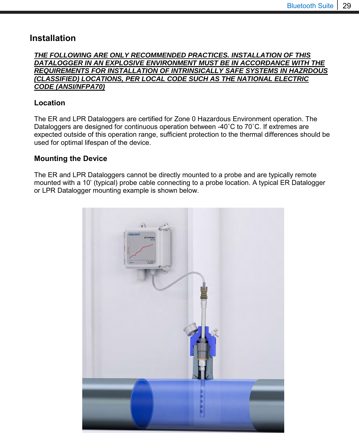
![67 Bluetooth Suite Chapter 8 ER Datalogger Create an ID for ER Datalogger On the Transfer Unit standby screen select Confg. On the next display screen, select ER to get to a list of ER devices. Select RDC2 from the list of devices. Enter the desired ID number then select OK. Enter the interval then select m for minutes or h for hours. Select Device ER | LPR | Microcor Ultracorr 2 | Exit ER Reader | Logr | RDC Back | Exit | Enter ID: [ _ ] (1 – 255) 0123456789.< OK Back Interval: [ _ ] min:(5-59) hr:(1-24) 0123456789< m h Back](https://usermanual.wiki/Rohrback-Cosasco-Systems/ER200.Users-Manual-1/User-Guide-3661881-Page-73.png)
![68 ER Datalogger Enter a tag name for the device then select Nxt. Enter in the name of the alloy then select Nxt. Note: The name of the alloy is for reference only and does not affect the calculation of corrosion rates. Select the probe type used with the ER Datalogger then select Next. If the user selects any of the Other probe options, the following screen will appear. Manually enter the span of the probe. Select if the probe is a temperature probe or not by selecting either Yes or No. Is it a Temp. Probe? Yes | No | Bck | Exit Tag:[ _ ] ABCDEFGHIJKLMNOPQRSTUVWXYZ0123456789._-< Clr | Nxt | Bck | Exit Alloy: [ _ ] ABCDEFGHIJKLMNOPQR STUVWXYZ0123456789._-< Clr | Nxt | Bck | Exit Select Probe Type < XX XXXXXXXXX X > Scroll up and down Next | Back | Exit Span:< > mils 0123456789.< OK Back](https://usermanual.wiki/Rohrback-Cosasco-Systems/ER200.Users-Manual-1/User-Guide-3661881-Page-74.png)
![69 Bluetooth Suite To save the configuration of the device select Okay. Load Configuration onto ER Datalogger To load a configuration onto the ER Datalogger an ID must be created. If the user has not already created an ID, please refer to the Create an ID for ER Datalogger section. On the device list screen, find the ER Datalogger device by pushing the up and down keys and select Cfg. Enter the ID of the configuration to load onto the ER Datalogger then select OK. Select Okay to load the configuration onto the ER Datalogger. Save? ID: XXX TAGNAME Okay | Back | Exit Devices [UP/DOWN] X [XXXXXXXXXX ] Bk=Back Sv=Save Cfg | Dl | St | Bk | Sv Enter ID:[ _ ] (1 – 255) 0123456789.< OK Back ID: XX TAGNAME Okay | Back | Exit](https://usermanual.wiki/Rohrback-Cosasco-Systems/ER200.Users-Manual-1/User-Guide-3661881-Page-75.png)
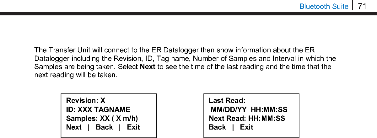
![70 ER Datalogger Download Data from ER Datalogger On the Transfer Unit device list, navigate to the ER Datalogger device and select Dl. After successful data transfer, a screen will display information about the ER Datalogger and the latest reading. Use Next to navigate between the screens and see the Alloy, Span, Divisions and Check Readings, Temperature, Metal Loss and the time that the last data point was collected from the device. Get Status of ER Datalogger On the Transfer Unit device list screen, navigate to the ER Datalogger device and select St. Devices [UP/DOWN] X [XXXXXXXXXX ] Bk=Back Sv=Save Cfg | Dl | St | Bk | Sv ID: XXX (X) RDC-COT Tag: XXXXXXX Samples XXX ( XX m/h) Next | Back | Exit Alloy: XX Span: XX.XXX mils Next | Back | Exit Div: XXX.X Chk: XXX.X Temp: XXXX.X C MLoss: X.XXX mils Next | Back | Exit Time Stamp: MM/DD/YY HH:MM:SS Interval: XX m/h Back | Exit Devices [UP/DOWN] X [XXXXXXXXXX ] Bk=Back Sv=Save Cfg | Dl | St | Bk | Sv](https://usermanual.wiki/Rohrback-Cosasco-Systems/ER200.Users-Manual-1/User-Guide-3661881-Page-76.png)
![73 Bluetooth Suite Chapter 8 LPR Datalogger Create an ID for LPR Datalogger On the Transfer Unit standby screen select Confg. On the next display screen, select LPR to get to a list of LPR devices. Select RDC2 from the list of devices. Enter the desired ID number then select OK. Enter the interval then select m for minutes or h for hours. Select Device ER | LPR | Microcor Ultracorr 2 | Exit LPR Reader | Logr | RDC Back | Exit | Enter ID: [ _ ] (1 – 255) 0123456789.< OK Back Interval: [ _ ] min:(10-59) hr:(1-24) 0123456789< m h Back](https://usermanual.wiki/Rohrback-Cosasco-Systems/ER200.Users-Manual-1/User-Guide-3661881-Page-79.png)
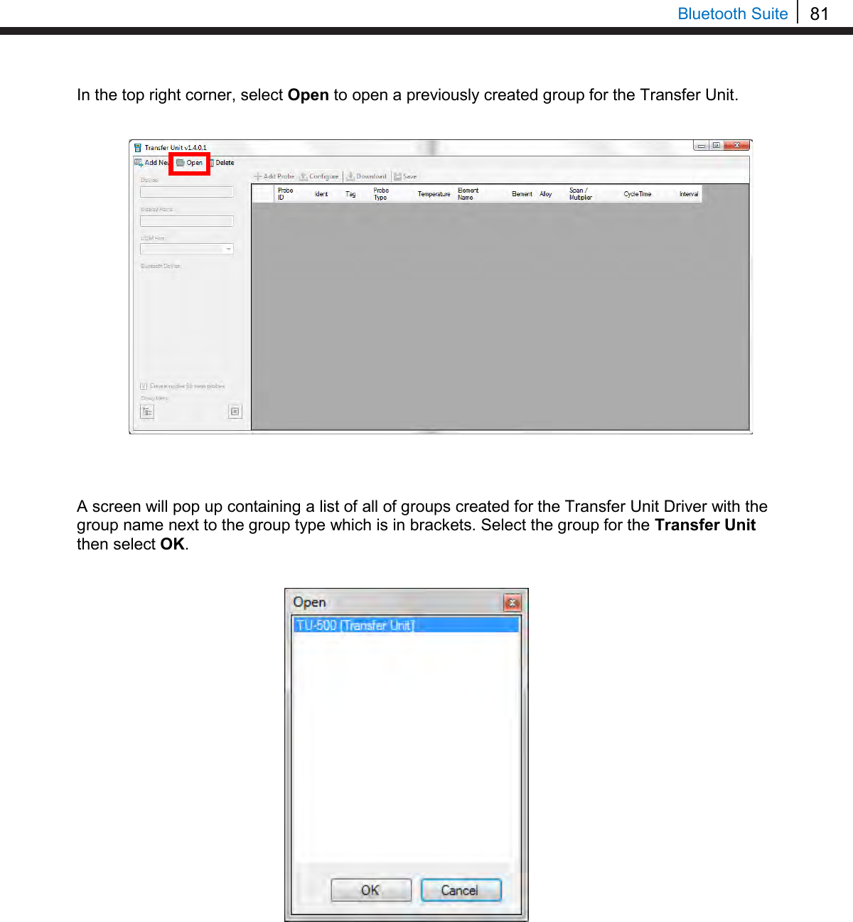
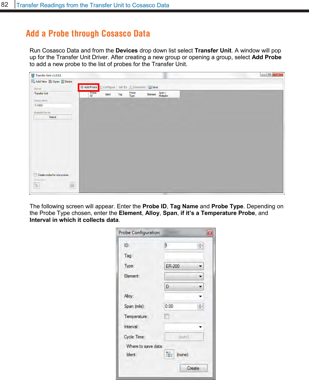
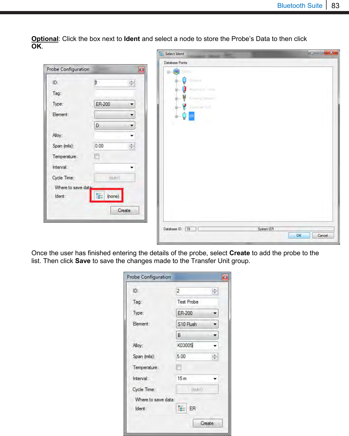
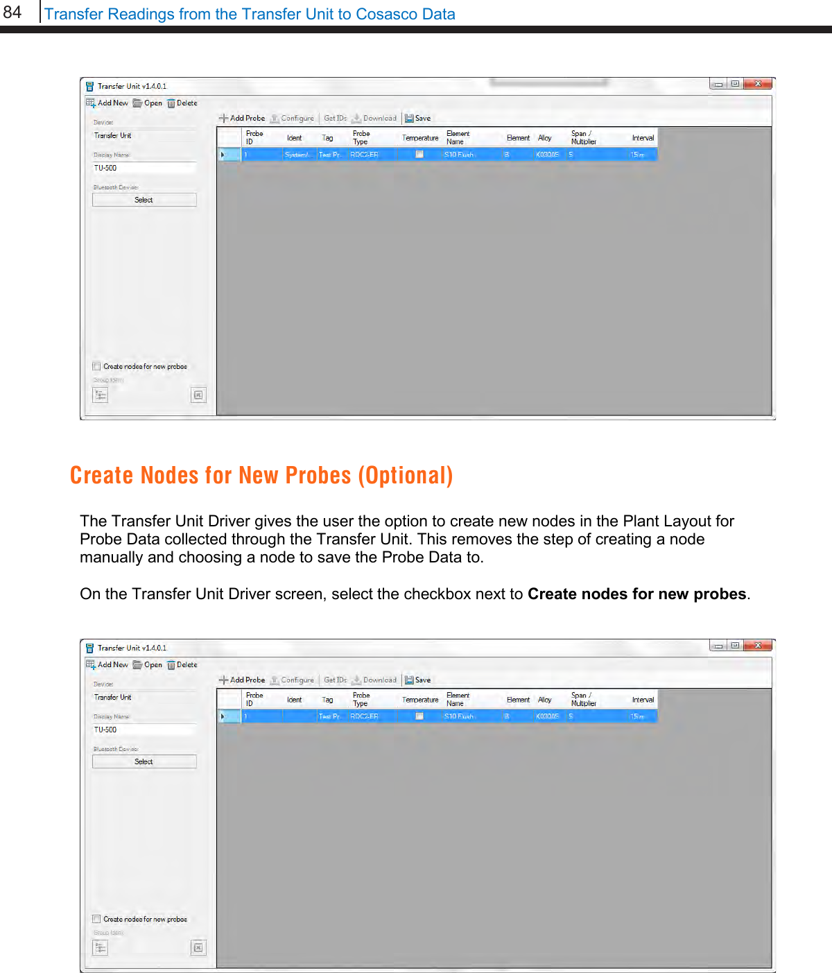
![74 Transfer Readings from the Transfer Unit to Cosasco Data Enter a tag name for the device then select Nxt. Select an alloy by using the up and down arrows to scroll through the choices then select Next. If Other is selected, the name of the alloy and the multiplier (mult) will have to be inputted manually. Select either Stdrd-E or Flush-F for the probe type. Select the cycle time for the device by selecting either Min or Auto. Select if the probe is a temperature probe or not by selecting either Yes or No. Tag:[ _ ] ABCDEFGHIJKLMNOPQRSTUVWXYZ0123456789._-< Clr | Nxt | Bck | Exit Alloy: [ _ ] ABCDEFGHIJKLMNOPQR STUVWXYZ0123456789._-< Clr | Nxt | Bck | Exit Mult:< > 0123456789.< OK Back Select Alloy XXXXXXXXXXXXX XXXXXX (scroll U/D) Next | Back | Exit Select Probe Type Stdrd-E | Flush-F Back | Exit Select Cycle Time in Minutes Min | Auto | Back Is it a Temp. Probe? Yes | No | Bck | Exit](https://usermanual.wiki/Rohrback-Cosasco-Systems/ER200.Users-Manual-1/User-Guide-3661881-Page-80.png)
![75 Bluetooth Suite To save the configuration of the device select Okay. Load Configuration onto LPR Datalogger To load a configuration onto the LPR Datalogger an ID must be created. If the user has not already created an ID, please refer to the Create an ID for LPR Datalogger section. On the device list screen, find the LPR Datalogger device by pushing the up and down keys and select Cfg. Enter the ID of the configuration to load onto the LPR Datalogger then select OK. Select Okay to load the configuration onto the LPR Datalogger. Save? ID: XXX TAGNAME Okay | Back | Exit Devices [UP/DOWN] X [XXXXXXXXXX ] Bk=Back Sv=Save Cfg | Dl | St | Bk | Sv Enter ID:[ _ ] (1 – 255) 0123456789.< OK Back ID: XX TAGNAME Okay | Back | Exit](https://usermanual.wiki/Rohrback-Cosasco-Systems/ER200.Users-Manual-1/User-Guide-3661881-Page-81.png)
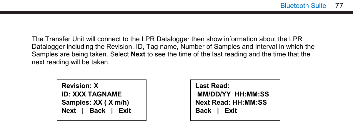
![76 Transfer Readings from the Transfer Unit to Cosasco Data Download Data from LPR Datalogger On the Transfer Unit device list, navigate to the LPR Datalogger device and select Dl. After successful data transfer, a screen will display information about the LPR Datalogger and the latest reading. Use Next to navigate between the screens and see the Alloy, Multiplier, Cycle Time, Rate, Imbalance, Temperature, Interval at which readings are being taken and the time that the last data point was collected from the device. Get Status of LPR Datalogger On the Transfer Unit device list screen, navigate to the LPR Datalogger device St. Devices [UP/DOWN] X [XXXXXXXXXX ] Bk=Back Sv=Save Cfg | Dl | St | Bk | Sv ID: XXX (X) RDC-COT Tag: XXXXXXX Samples XXX ( XX m/h) Next | Back | Exit Alloy: XX Span: XX.XXX mils Next | Back | Exit Div: XXX.X Chk: XXX.X Temp: XXXX.X C MLoss: X.XXX mils Next | Back | Exit Time Stamp: MM/DD/YY HH:MM:SS Interval: XX m/h Back | Exit Devices [UP/DOWN] X [XXXXXXXXXX ] Bk=Back Sv=Save Cfg | Dl | St | Bk | Sv](https://usermanual.wiki/Rohrback-Cosasco-Systems/ER200.Users-Manual-1/User-Guide-3661881-Page-82.png)