RuiXingHengFang Network 76052 RHF76-052 Module User Manual
RuiXingHengFang Network(Shenzhen) Co., Ltd. RHF76-052 Module Users Manual
UserManual.wiki
>
RuiXingHengFang Network
>
76052 User Manual
Users Manual
Navigation menu
Upload a User Manual
Namespaces
Wiki Guide
HTML
PDF
Info
Views
User Manual
Discussion / Help
Navigation
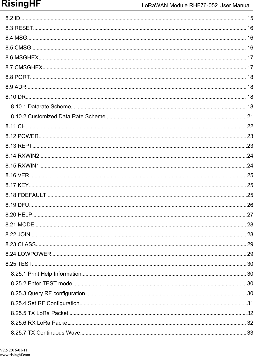
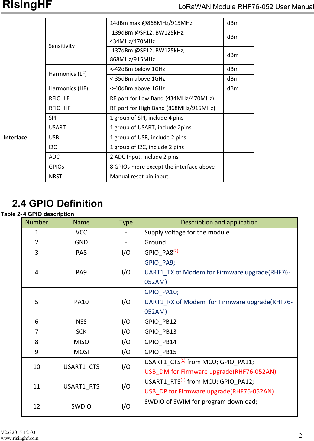
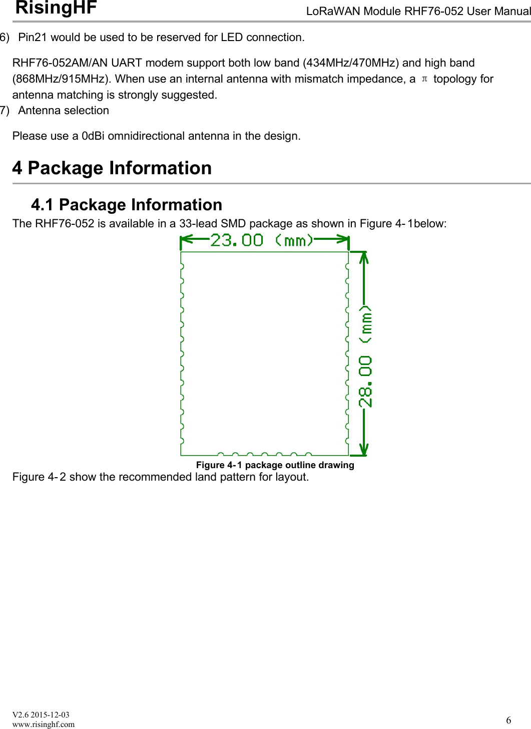
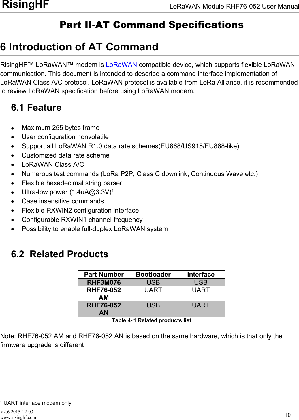
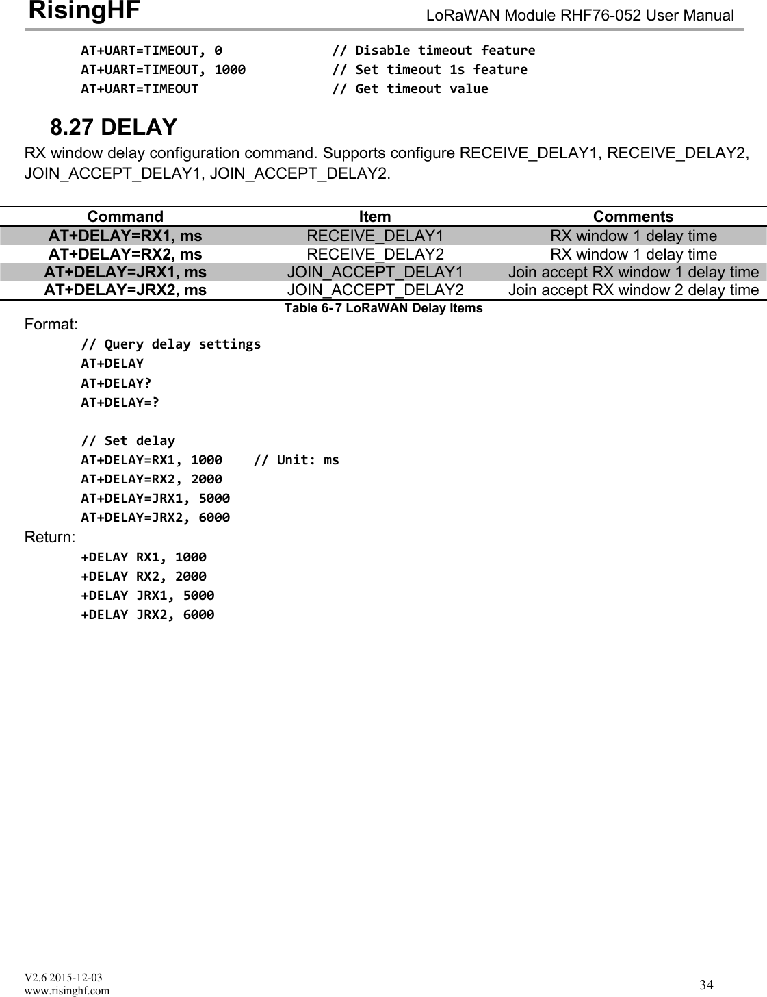
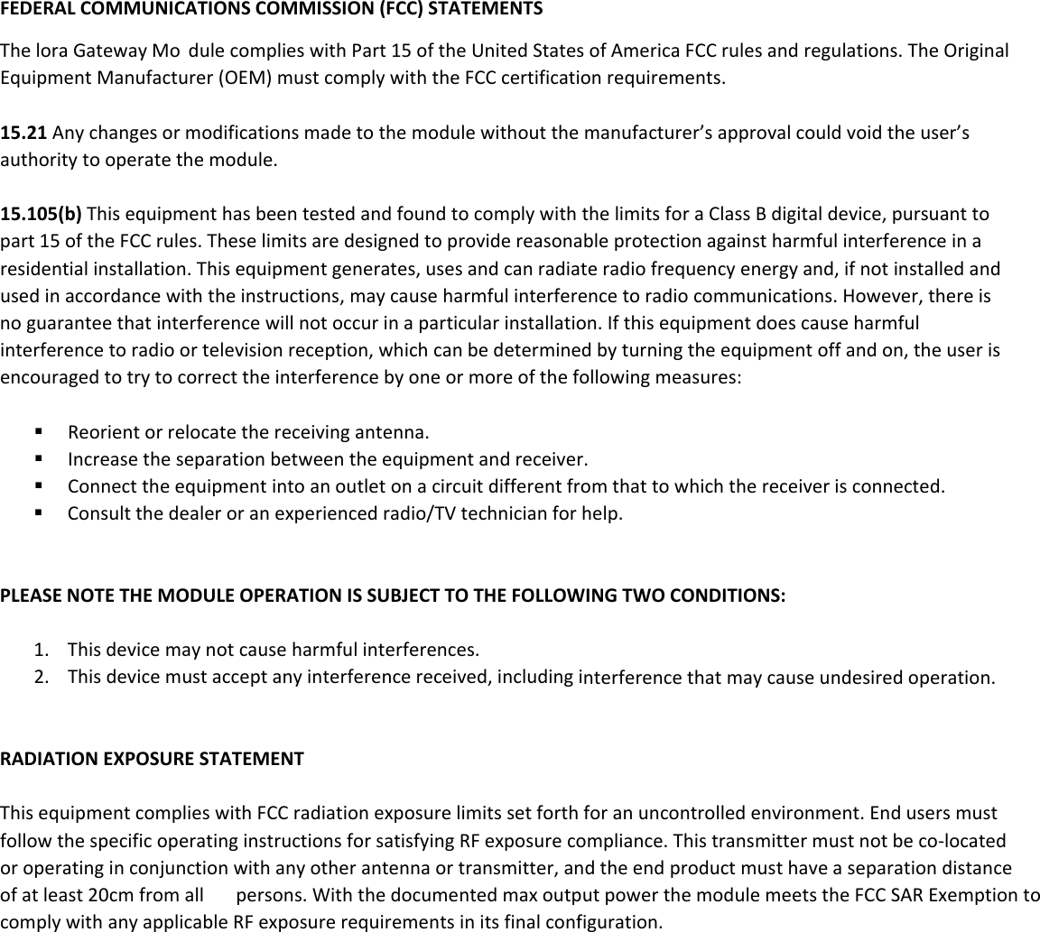
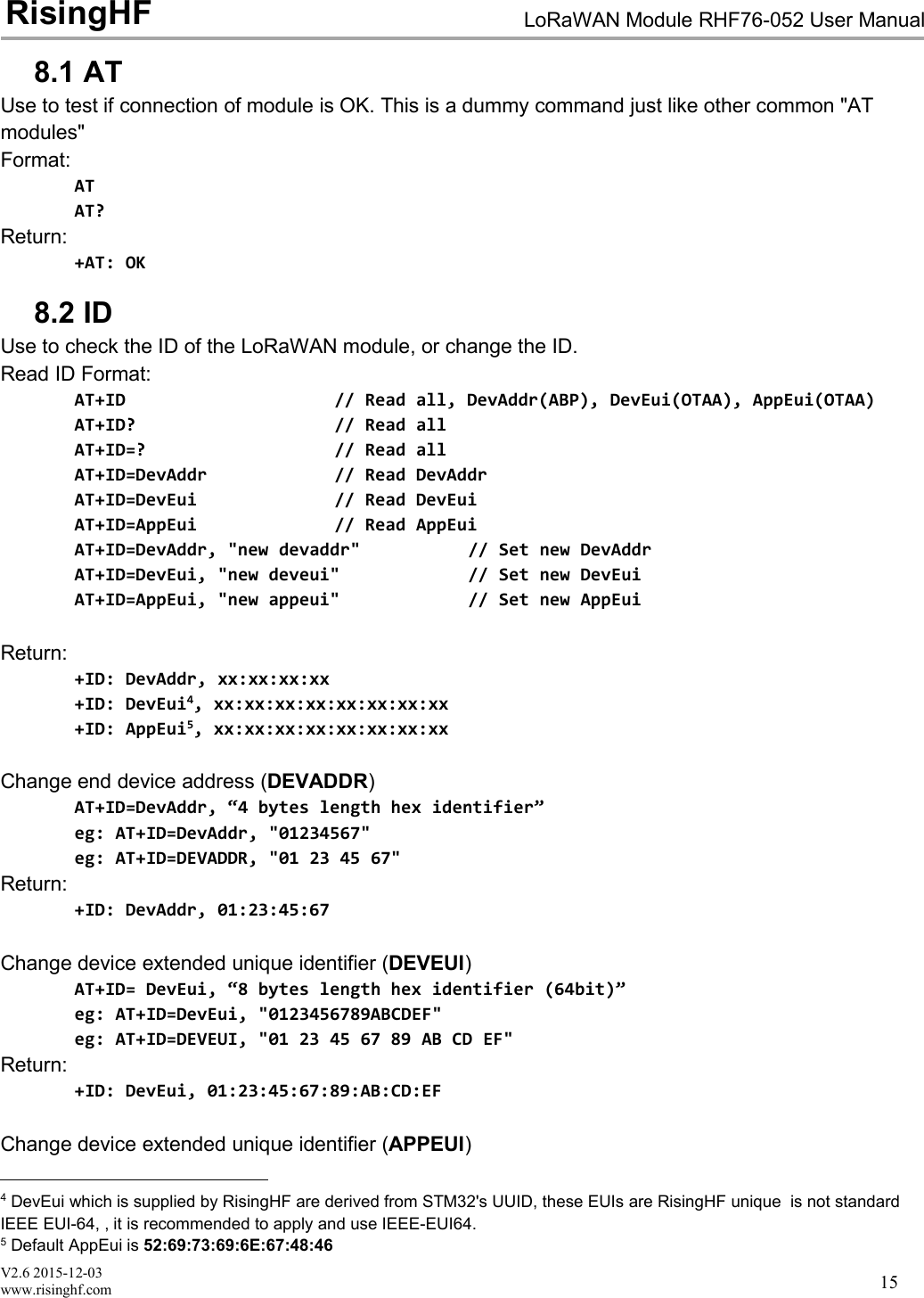
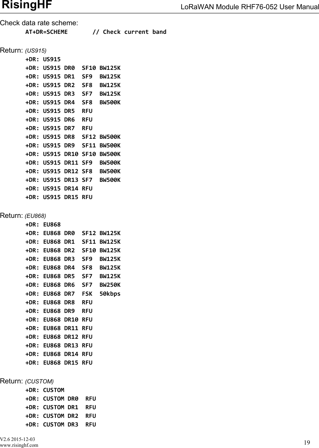
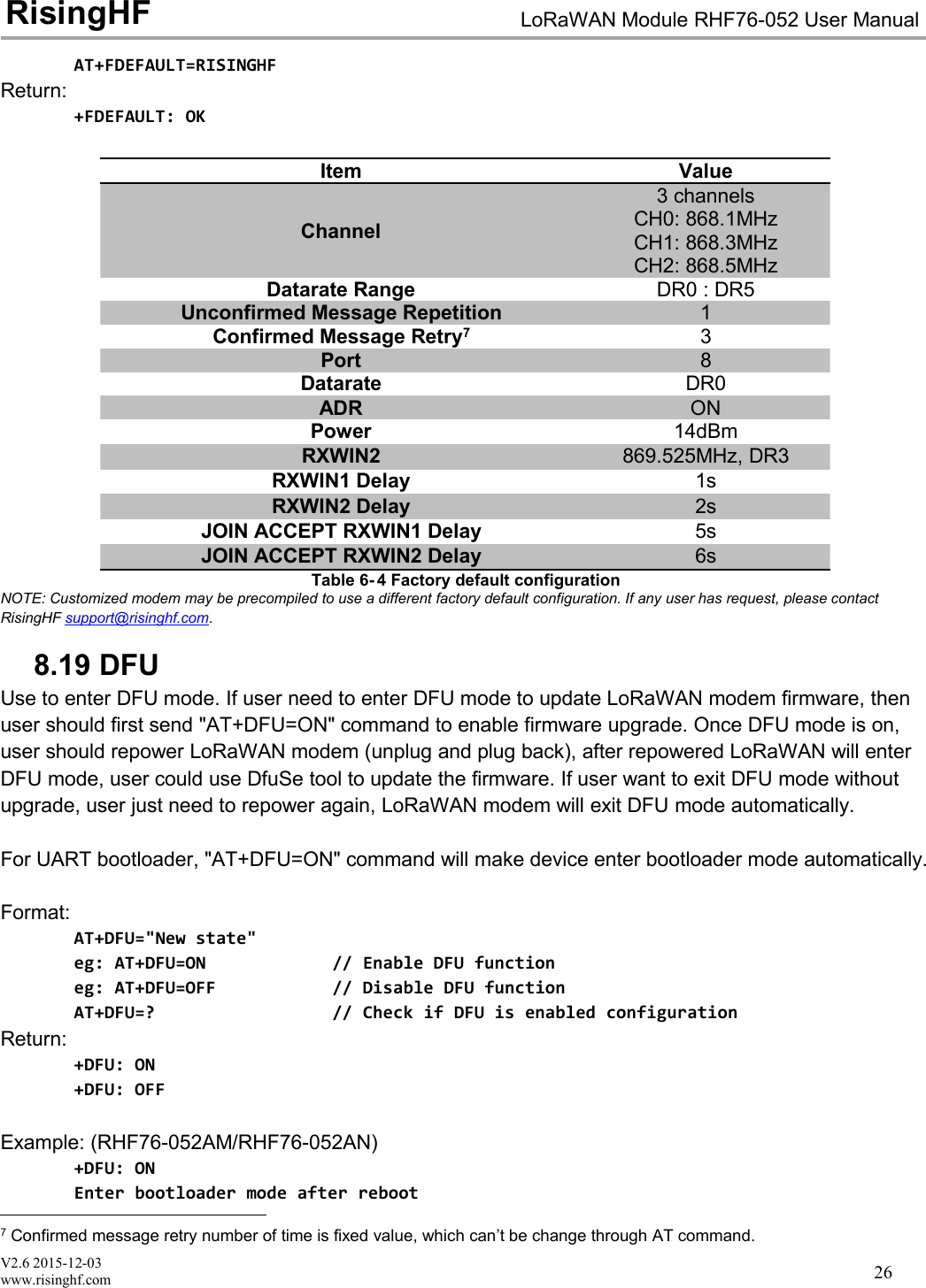
![V2.6 2015-12-03www.risinghf.comLoRaWAN Module RHF76-052 User ManualRisingHF148 AT Commands descriptionCommandDescriptionATTest commandHELPPrint command listFDEFAULTFactory data resetRESETSoftware resetDFUForce bootloader to enter dfu modeLOWPOWEREnter sleep modeVERVersion[Major.Minor.Patch]MSGLoRaWAN unconfirmed dataMSGHEXLoRaWAN unconfirmed data in hexCMSGLoRaWAN confirmed dataCMSGHEXLoRaWAN confirmed data in hexCHLoRaWAN channel frequencyDRLoRaWAN datarateADRLoRaWAN ADR controlREPTUnconfirmed message repetitionPOWERLoRaWAN TX powerRXWIN2LoRaWAN RX window2RXWIN1Customized RXWIN1 frequencyPORTLoRaWAN communication portMODELWABP, LWOTAA, TESTIDLoRaWAN DevAddr/DevEui/AppEuiKEYSet NWKSKEY/APPSKEY/APPKEYCLASSChoose LoRaWAN modem class(A/B/C)JOINLoRaWAN OTAA JOINTESTSend test serious commandUARTUART configureDELAYRX window delayTable 6- 1 Command List](https://usermanual.wiki/RuiXingHengFang-Network/76052/User-Guide-3211045-Page-19.png)
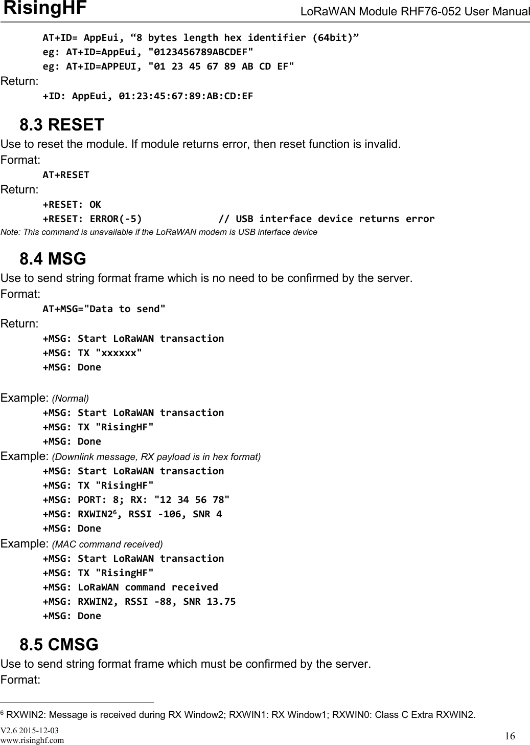
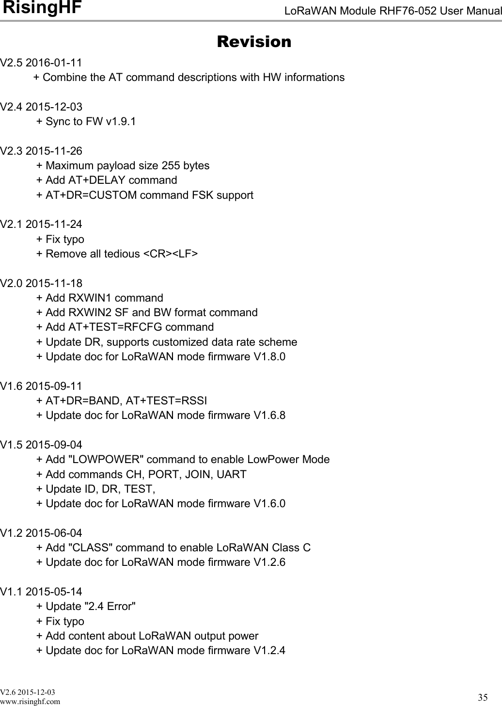
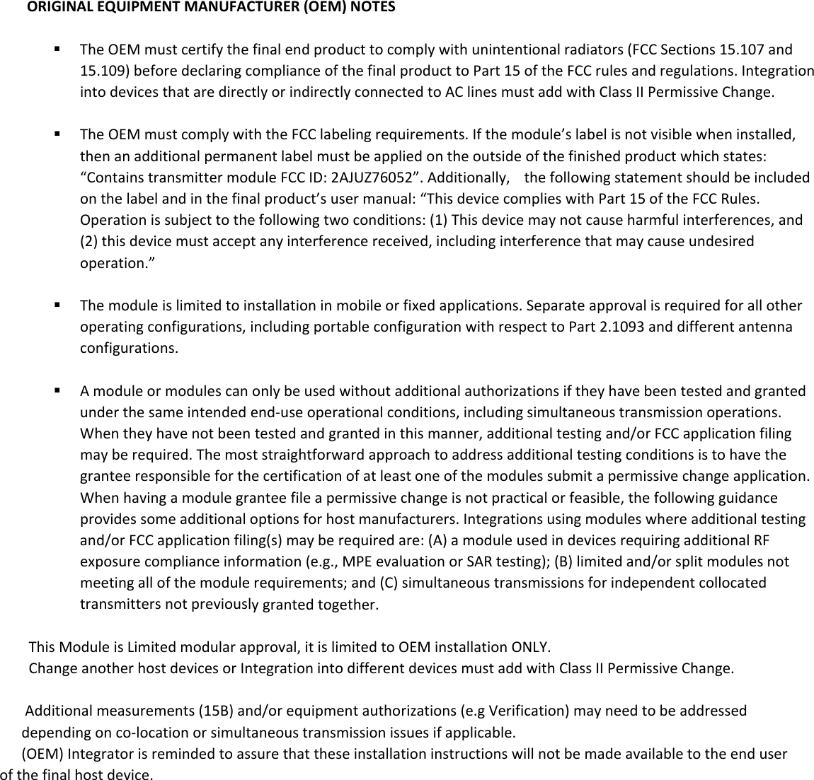
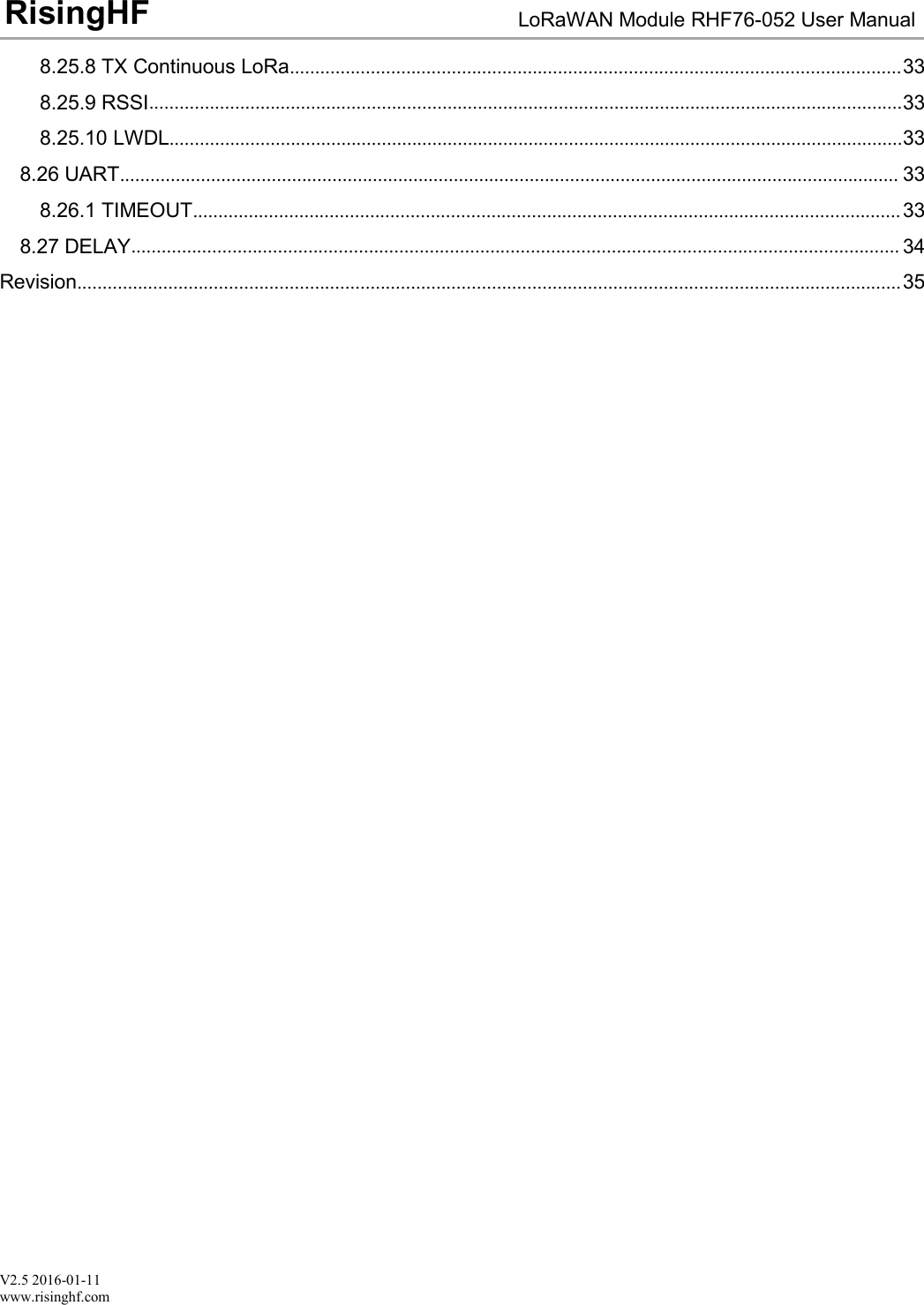
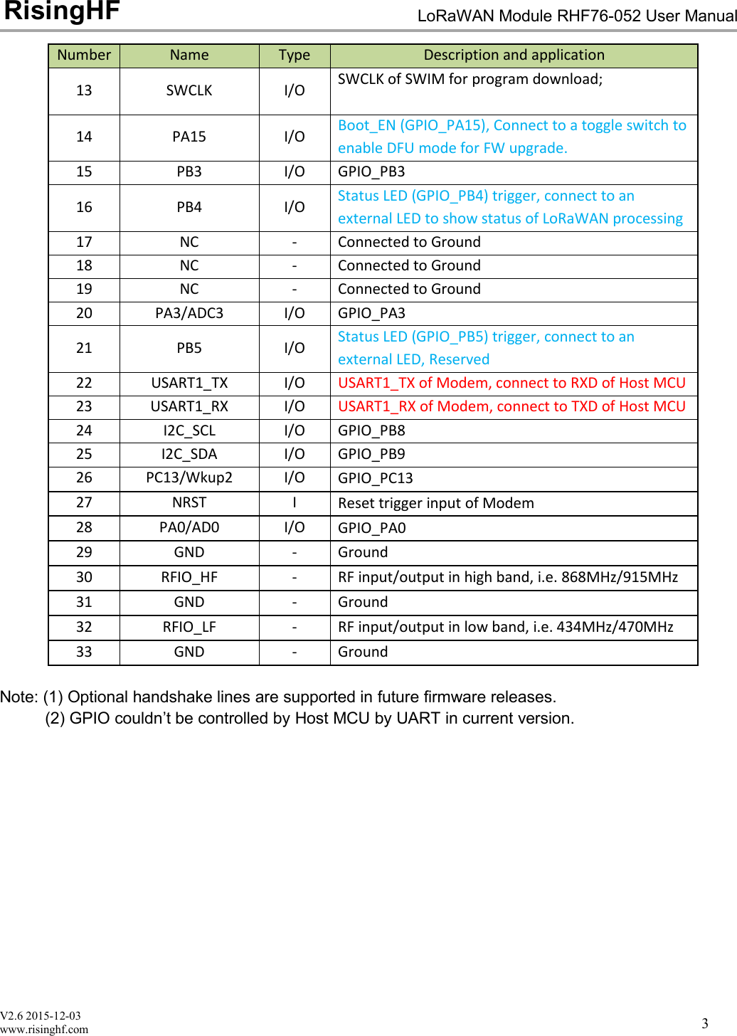
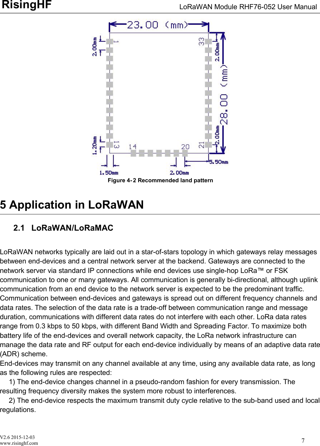
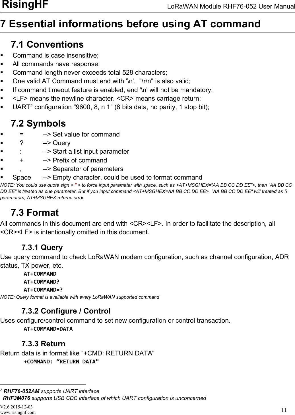
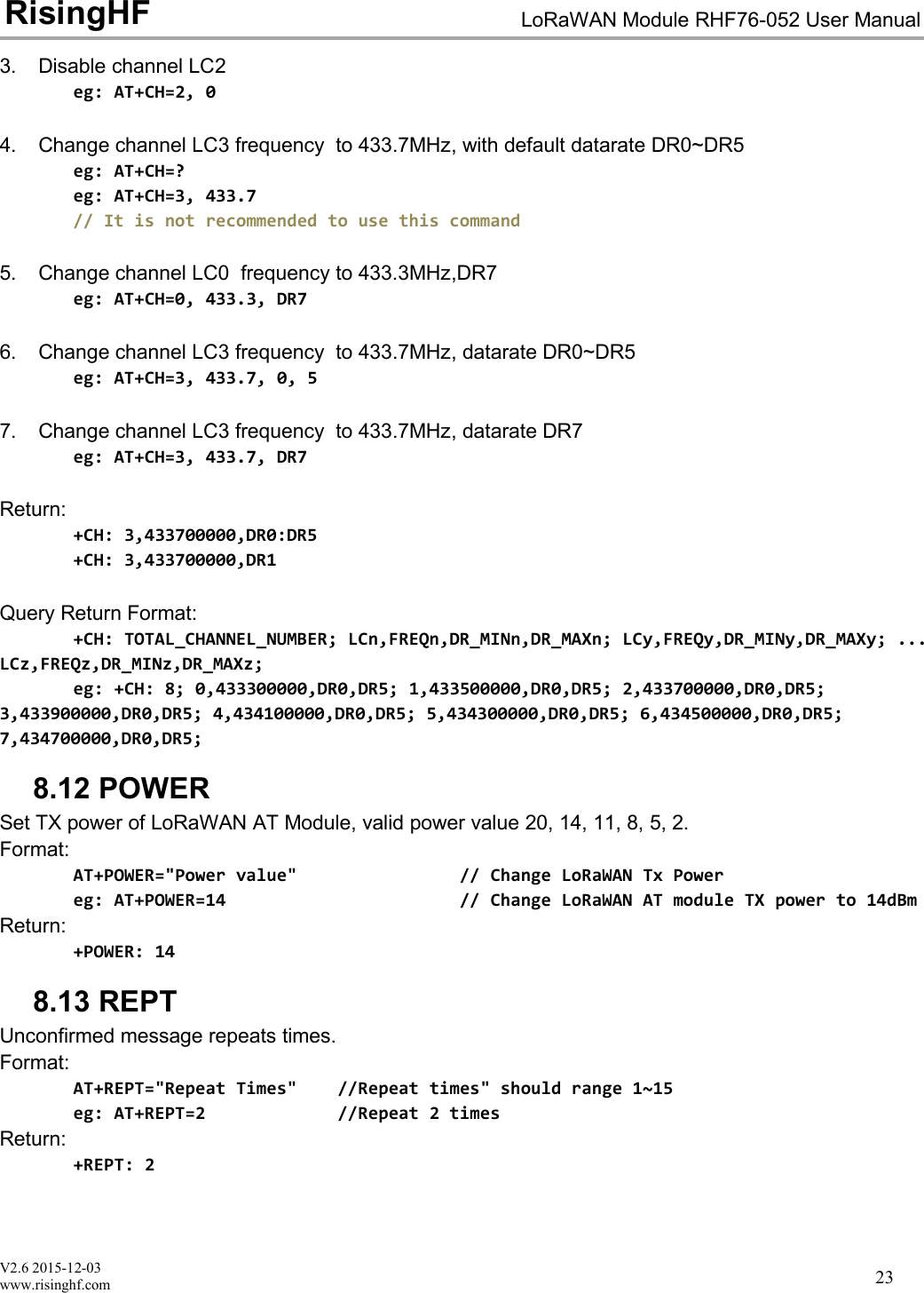
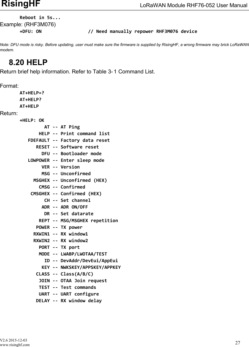
![V2.6 2015-12-03www.risinghf.comLoRaWAN Module RHF76-052 User ManualRisingHF20+DR: CUSTOM DR4 RFU+DR: CUSTOM DR5 RFU+DR: CUSTOM DR6 RFU+DR: CUSTOM DR7 RFU+DR: CUSTOM DR8 RFU+DR: CUSTOM DR9 RFU+DR: CUSTOM DR10 RFU+DR: CUSTOM DR11 RFU+DR: CUSTOM DR12 RFU+DR: CUSTOM DR13 RFU+DR: CUSTOM DR14 RFU+DR: CUSTOM DR15 RFUChoose data rate schemeAT+DR=EU868 // LoRaWAN EU868 data rate schemeAT+DR=US915 // LoRaWAN US915 data rate schemeAT+DR=CUSTOM // Customized data rate schemeLoRaWAN Data RateConfigurationIndicative physicalbit rate [bit/s]DR0LoRa SF12/125KHz250DR1LoRa SF11/125KHz440DR2LoRa SF10/125KHz980DR3LoRa SF9/125KHz1760DR4LoRa SF8/125KHz3125DR5LoRa SF7/125KHz5470DR6LoRa SF7/250KHz11000DR7FSK:50kbps50000DR8-DR15RFURFUTable 6- 2 LoRaWAN EU868 Data Rate SchemeLoRaWAN Data RateConfigurationIndicative physicalbit rate [bit/s]DR0LoRa SF10/125KHz980DR1LoRa SF9/125KHz1760DR2LoRa SF8/125KHz3125DR3LoRa SF7/125KHz5470DR4LoRa SF8/500KHz12500DR5-DR7RFURFUDR8LoRa SF12/500KHz980DR9LoRa SF11/500KHz1760DR10LoRa SF10/500KHz3900DR11LoRa SF9/500KHz7000DR12LoRa SF8/500KHz12500DR13LoRa SF7/500KHz21900DR14-DR15RFURFUTable 6- 3 LoRaWAN US915 Data Rate Scheme](https://usermanual.wiki/RuiXingHengFang-Network/76052/User-Guide-3211045-Page-25.png)
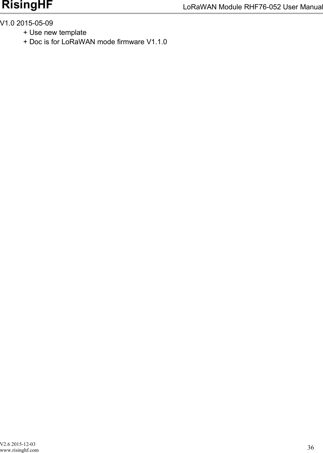
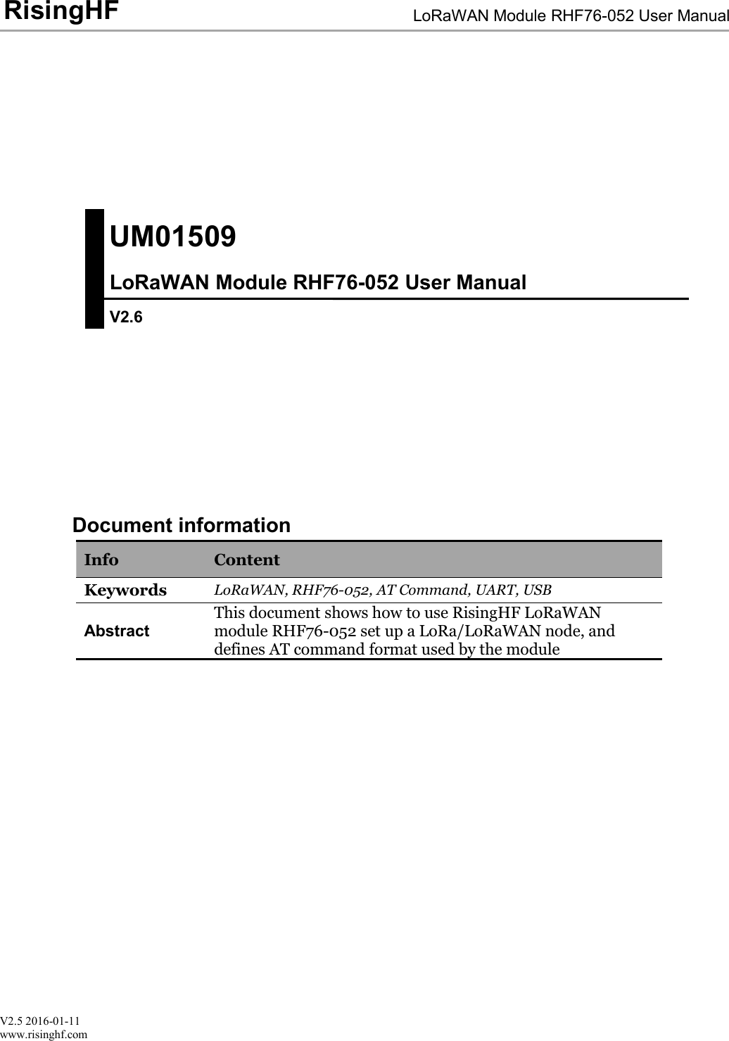
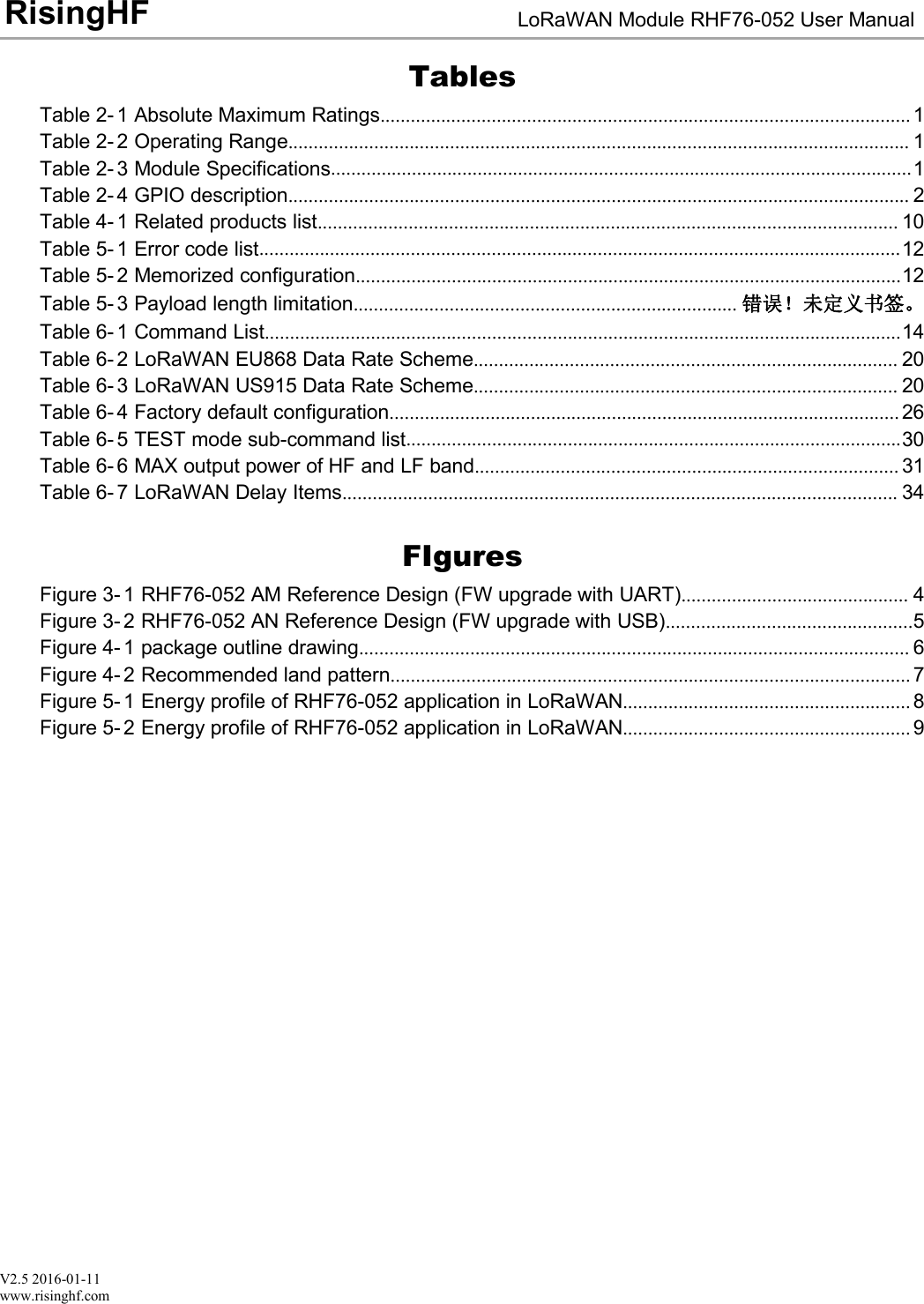
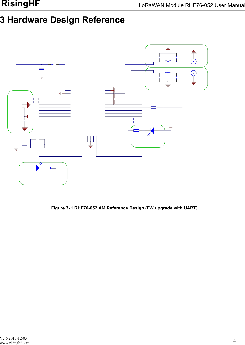
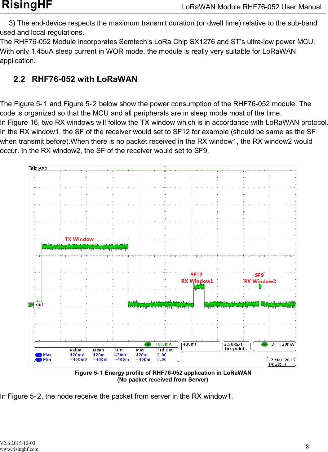
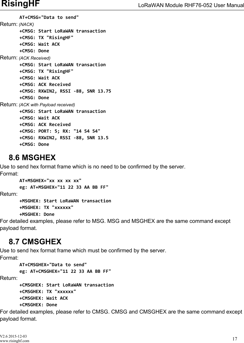
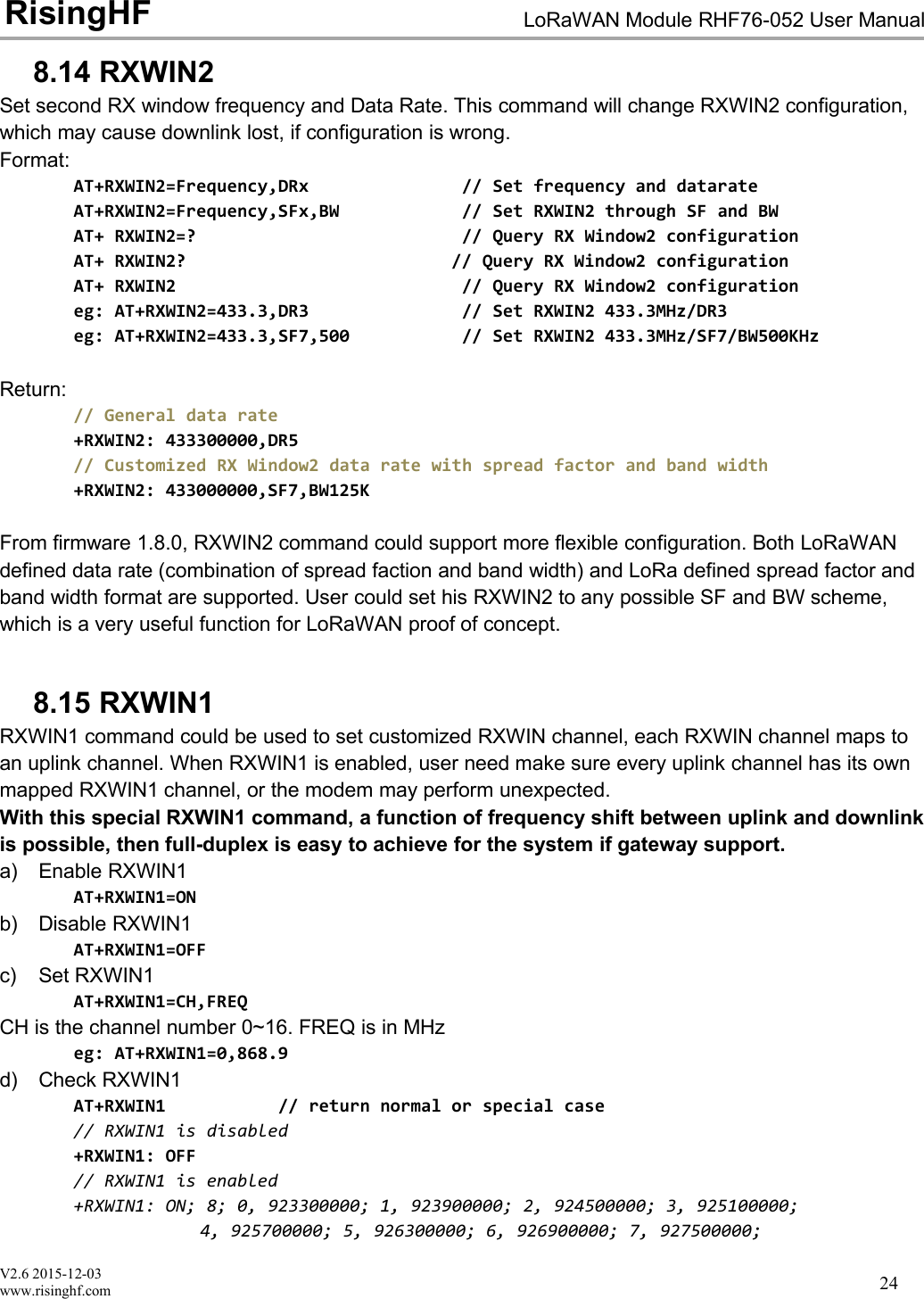
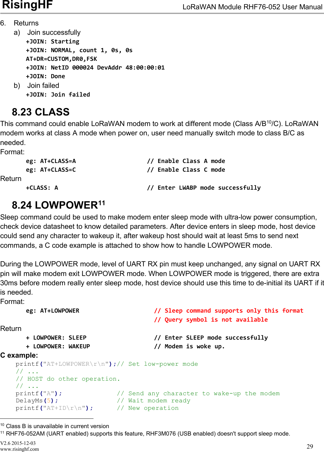
![V2.6 2015-12-03www.risinghf.comLoRaWAN Module RHF76-052 User ManualRisingHF218.10.2 Customized Data Rate SchemeIn order to provide maximum flexibility to define data rate, this customized data rate scheme feature isadded from firmware v1.8.0.Define a new data rate:AT+DR=CUSTOM, DRx, SFx, BW, [DRx (RXWin1)]Note: [DRx (RXWin1)] is optional parameter, which could be used to specify an RXWin1 data rate for apredefined data rate. For example, “AT+DR=CUSTOM, DR0, SF10, 500, DR4” will map DR0 and DR4, thismeans when sending a message use DR0, RXWIN1 will set DR11 to receive downlink. This feature isuseful when downlink output power is higher than uplink, in this situation, it is reasonable to use higherdata rate and still keep uplink budget and downlink budget balance, and make whole network highefficient. If absent, RXWIN1 data rate will be set to the same as uplink data rate in default.Set data rate to RFU (Reserve For Use)AT+DR=CUSTOM, DRx, RFUExample:// Set DR0 to SF7 and BW125KHzAT+DR=CUSTOM, DR0, SF7, 125Return:+DR: CUSTOM DR0 SF7 BW125K //By default downlink DR is the same as uplink DRExample:// Set DR0 to SF9 and BW500KHz, and map DR0 (uplink) with DR11 (downlink).AT+DR=CUSTOM, DR3, SF10, 500, DR4Return:+DR: CUSTOM DR3 SF10 BW500K DLDR4Example:// Set DR0 to FSK 50kpbsAT+DR=CUSTOM,DR0,FSKReturn:+DR: CUSTOM DR0 FSK 50kbpsExample:// Set DR0 to FSK 50kpbs, and map DR0 with DR5,// Note: [BW] parameter should be set to 0 or any other integer.AT+DR=CUSTOM,DR0,FSK,0,DR5Return:+DR: CUSTOM DR0 FSK 50kbpsExample:// Set DR0 to RFUAT+DR=CUSTOM, DR0, RFU](https://usermanual.wiki/RuiXingHengFang-Network/76052/User-Guide-3211045-Page-26.png)
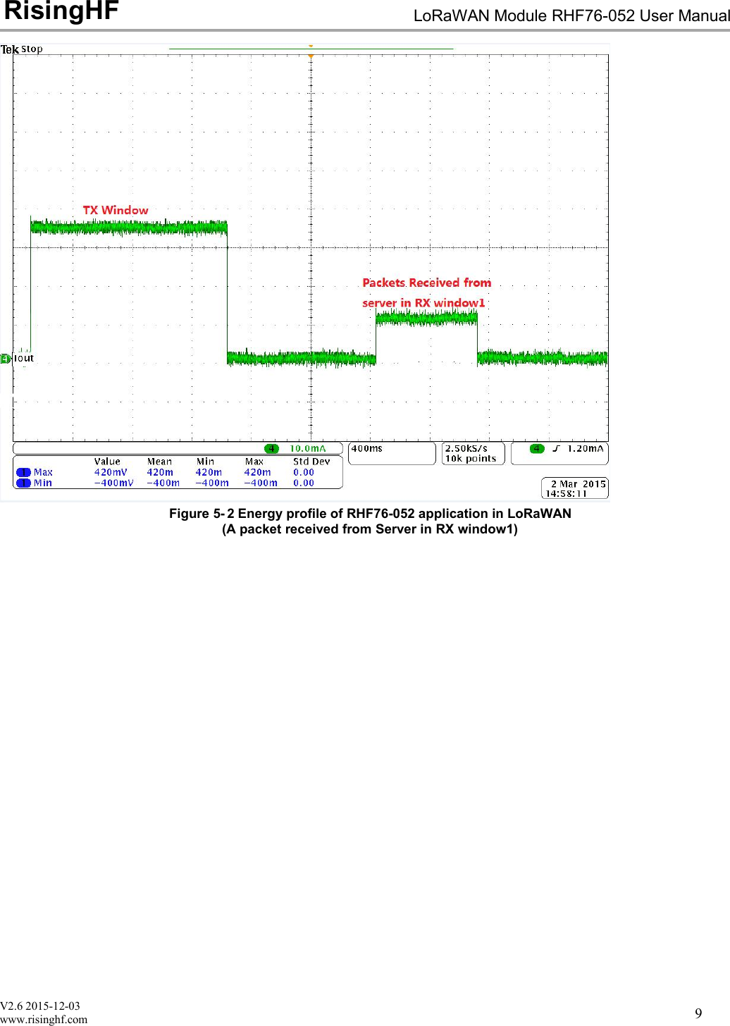
![V2.6 2015-12-03www.risinghf.comLoRaWAN Module RHF76-052 User ManualRisingHF22Return:+DR: CUSTOM DR0 RFUExample:// Check custom data rate schemeAT+DR=CUSTOMAT+DR=SCHEMEReturn:+DR: CUSTOM+DR: CUSTOM DR0 SF7 BW125K+DR: CUSTOM DR1 RFU+DR: CUSTOM DR2 RFU+DR: CUSTOM DR3 SF10 BW500K DLDR4+DR: CUSTOM DR4 RFU+DR: CUSTOM DR5 RFU+DR: CUSTOM DR6 RFU+DR: CUSTOM DR7 RFU+DR: CUSTOM DR8 RFU+DR: CUSTOM DR9 RFU+DR: CUSTOM DR10 RFU+DR: CUSTOM DR11 RFU+DR: CUSTOM DR12 RFU+DR: CUSTOM DR13 RFU+DR: CUSTOM DR14 RFU+DR: CUSTOM DR15 RFUNote: After changing the data rate scheme, user should run commands below to check if the data ratesettings are valid, and make sure no RFU data rate is used.AT+CHAT+RXWIN2AT+DR8.11 CHSet channel parameter of LoRaWAN modem, Set frequecy zero to disable one channel.Format:AT+CH="LCn", ["Freq"], ["DR_MIN"], ["DR_MAX"]// Change the LCn channel frequency to "Freq"// "Freq" is in MHz.// Available DR_MIN/DR_MAX range DR0 ~ DR151. Change channel LC0 frequency to 433.3MHz, datarate DR0~DR5eg: AT+CH=0, 433.3, DR0, DR52. Change channel LC1 frequency to 433.5MHz, datarate DR0~DR2eg: AT+CH=1, 433.5, DR0, DR2](https://usermanual.wiki/RuiXingHengFang-Network/76052/User-Guide-3211045-Page-27.png)
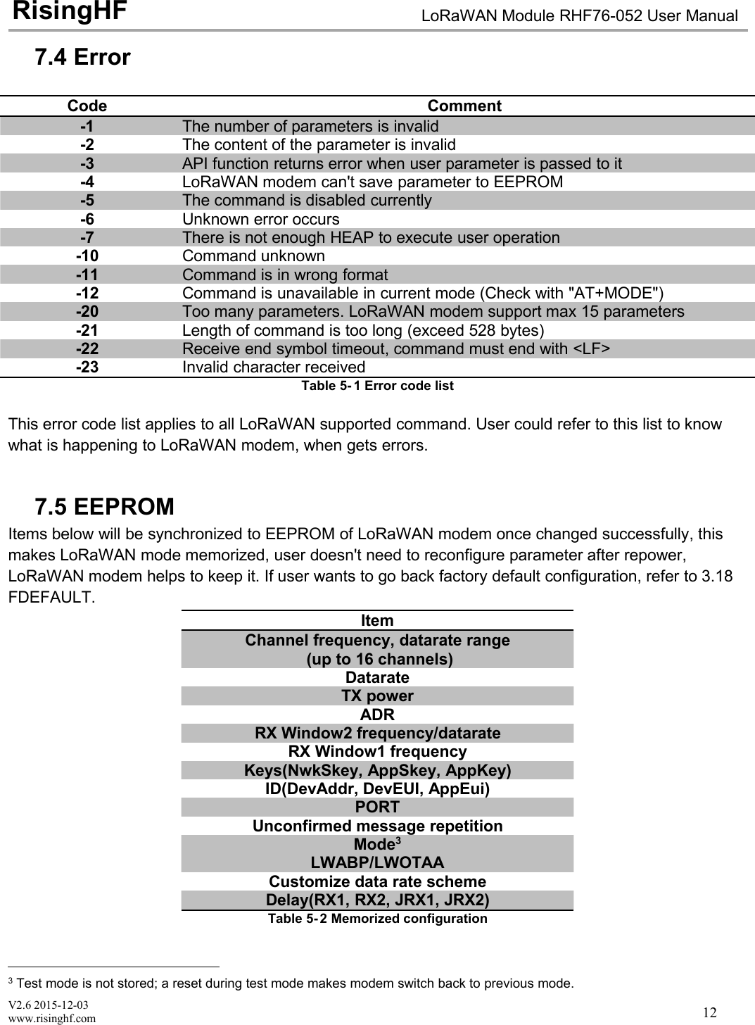
![V2.6 2015-12-03www.risinghf.comLoRaWAN Module RHF76-052 User ManualRisingHF288.21 MODEUse to select work mode. LWABP8, LWOTAA9, TEST are supported. LoRaWAN modem can only workwith one mode at a time. By default, LWABP is enabled, all test commands are unavailable, LoRaWANwill return error(-12) if it receives test command in non-test mode."AT+MODE" command will reset LoRaWAN stack when first enter LWABP/LWOTTA mode and resetLoRa chip when first enter test mode.LWABP/LWOTAA mode status is remembered by LoRaWAN modem, each time LoRaWAN modemstarts, it will enter previous working mode before reset or repower.Format:AT+MODE="New mode"eg: AT+MODE=TEST // Enter TEST modeeg: AT+MODE=LWOTAA // Enter TEST modeeg: AT+MODE=LWABP // Enter LWABP modeReturn+MODE: LWABP // Enter LWABP mode successfully+MODE: LWOTAA // Enter LWABP mode successfully+MODE: TEST // Enter TEST mode successfully8.22 JOINWhen OTAA mode is enabled, JOIN command could use to join a known network.Format:AT+JOIN=["Times"], ["DELAY"], ["DELAY RANDOM OFFSET"]AT+JOIN=REJOIN1. Queryeg: AT+JOIN=? // Query JOIN statuseg: AT+JOIN? // Query JOIN status2. Joineg: AT+JOIN // Send JOIN request3. Disconnect with current network, force send one JOIN requesteg: AT+JOIN=FORCE4. Stop JOINeg: AT+JOIN=STOP5. Auto send JOIN request 10 times with (20 +/- 4)s delay, set times to 0 join forever.eg: AT+JOIN=10, 20, 4eg: AT+JOIN=0 // JOIN forever with default delay(10 +/- 2)s8LWABP is short for LoRaWAN Activation ByPersonalization. Check < LoRaWAN™ Specification> for details9LWOTAA is short for LoRaWAN Over-The-Air-Activation.](https://usermanual.wiki/RuiXingHengFang-Network/76052/User-Guide-3211045-Page-33.png)
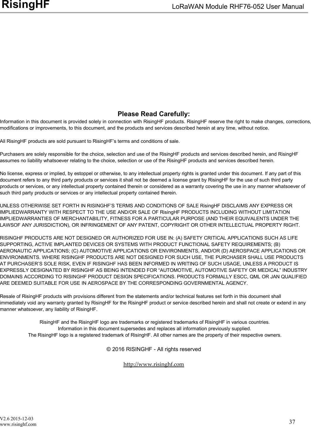
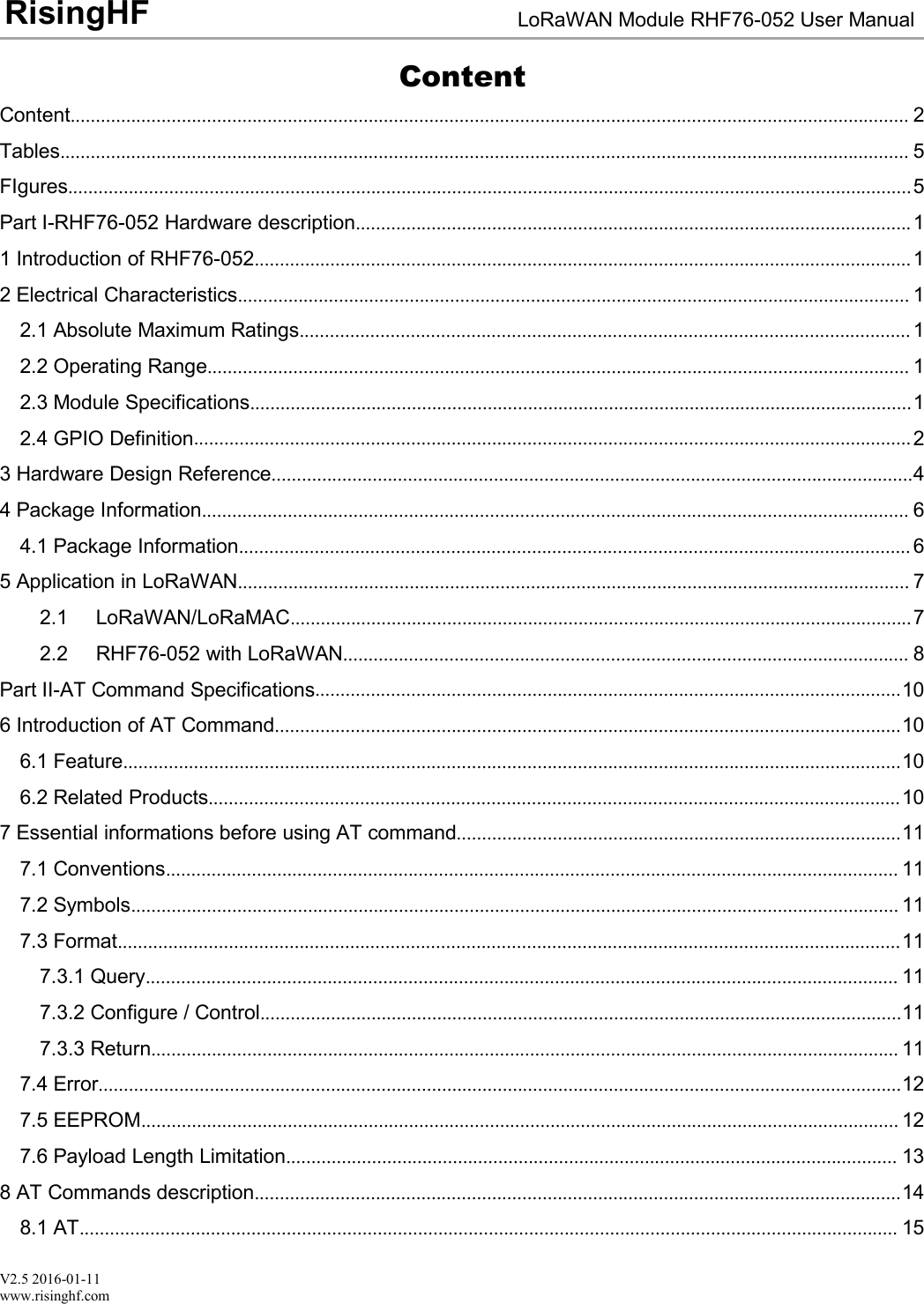
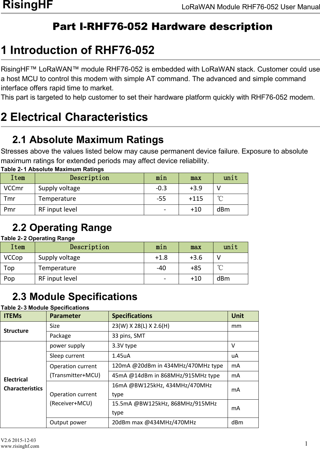
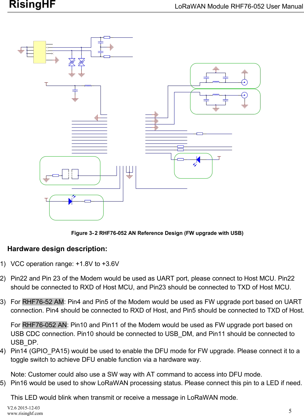
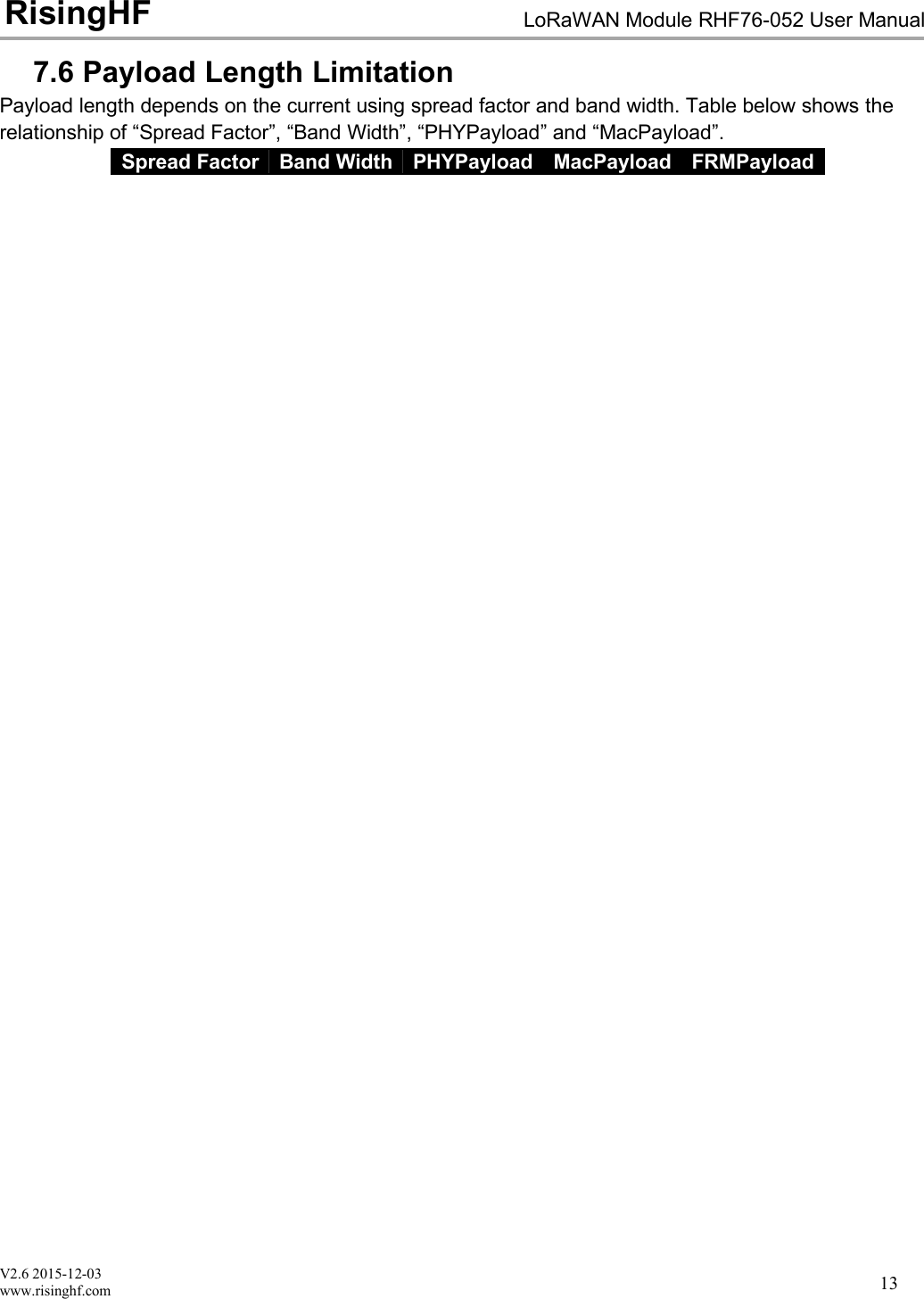
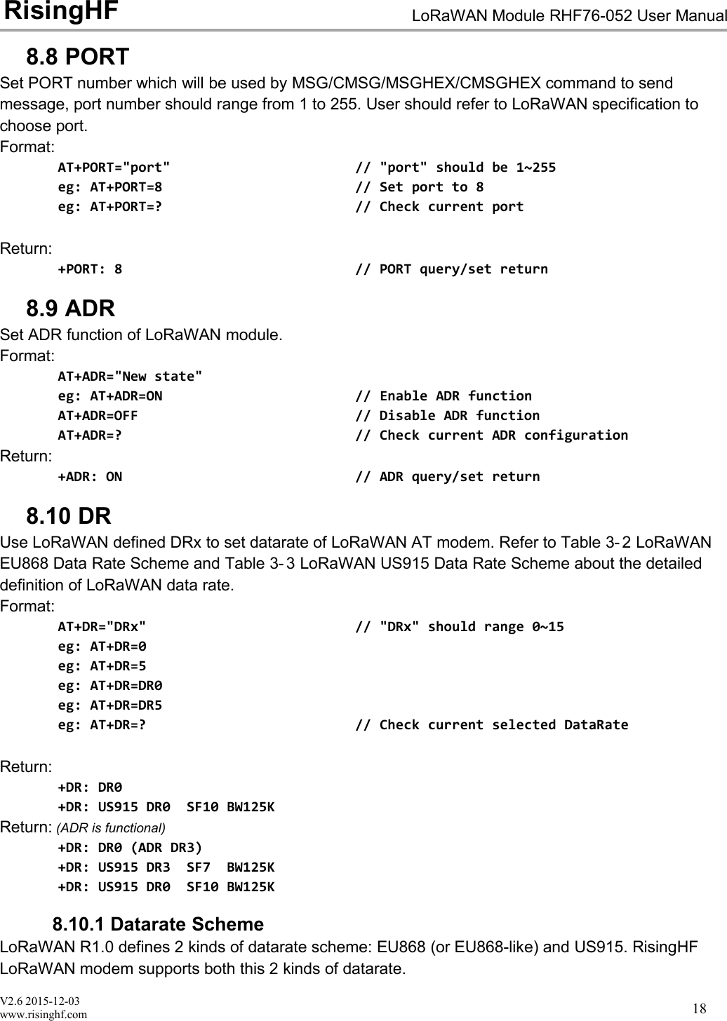
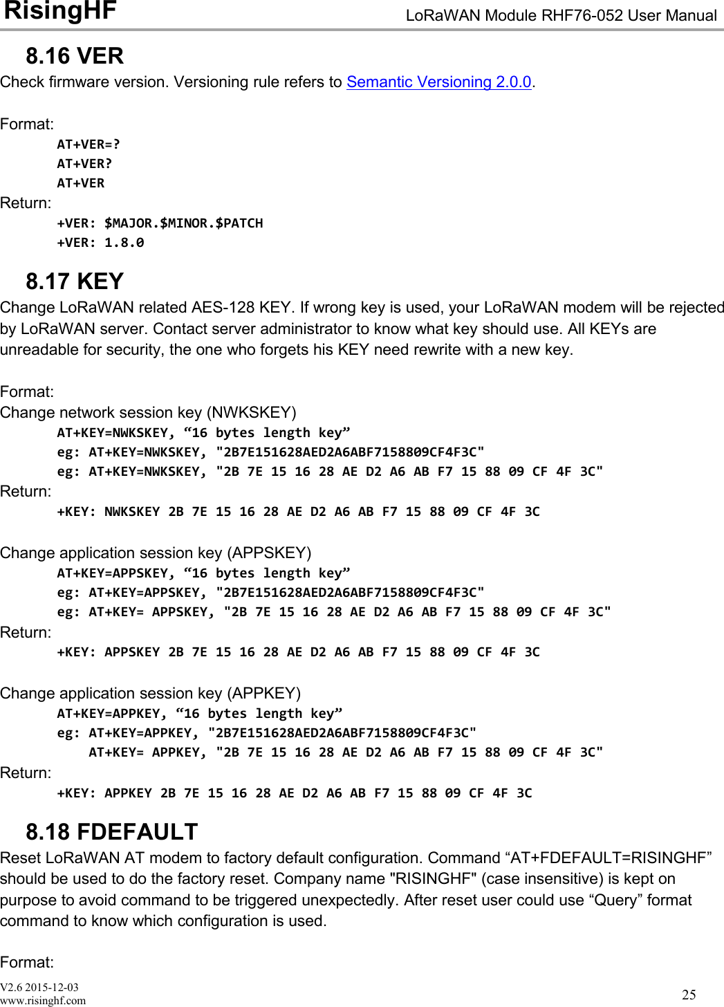
![V2.6 2015-12-03www.risinghf.comLoRaWAN Module RHF76-052 User ManualRisingHF308.25 TESTTEST command is not like other command, it is a serious command, includes several sub-commands,refer to table below. With test mode, user could do RF performance test quickly without any knowledgeof LoRa chip. Commands which are related to RF configuration is disabled in test mode.Sub-CommandCommentHELPPrint test command help information, make LoRa transceiver to standby modeSTOPSet LoRaWAN Modem to TEST stop modeTXCWTransmit continuous waveTXCLORATransmit continuous LoRa signalRFCFGSet RF configuration in TEST modeRXLRPKTContinuous receive pure LoRa packet, print once there is new packet receivedTXLRPKTSend one HEX format packet outTXLRSTRSend one string format packetRSSIGet RSSI value of specified channelLWDLSend LoRaWAN downlink packet, useful tool to test CLASS C deviceTable 6- 5 TEST mode sub-command list8.25.1 Print Help InformationFormat:AT+TSET=HELPReturn:+TEST: HELPSTOP -- AT+TEST=STOPHELP -- AT+TSET=HELPTXCW -- AT+TEST=TXCWTXCLORA -- AT+TEST=TXCLORARFCFG -- AT+TEST=RFCFG,[F],[SF],[BW],[TXPR],[RXPR],[POW]RXLRPKT -- AT+TEST=RXLRPKTTXLRPKT -- AT+TEST=TXLRPKT,"HEX"TXLRSTR -- AT+TEST=TXLRSTR,"TEXT"RSSI -- AT+TEST=RSSI,F,[CNT]LWDL -- AT+TEST=LWDL,TYPE,DevAddr,"HEX",[FCNT],[FPORT],[FCTRL]"[ ]" means the parameter is omissible together with parameters behind it8.25.2 Enter TEST modeBefore use any TEST command, LoRaWAN should work in test mode, or error code -12 will bereported.Command:AT+MODE=TESTReturn:+MODE: TEST // LoRaWAN modem enter TEST mode successfully8.25.3 Query RF configurationFirst thing after enter TEST mode should be check RF configuration.Command:](https://usermanual.wiki/RuiXingHengFang-Network/76052/User-Guide-3211045-Page-35.png)
![V2.6 2015-12-03www.risinghf.comLoRaWAN Module RHF76-052 User ManualRisingHF31AT+TEST=? // Query test mode and RF configurationReturn Error:+TEST: ERROR(-12)When come with ERROR(-12), user could try "AT+MODE=?" to check if LoRaWAN modem is in TEST mode, if not user should enter testmode first.Return STOP:+TEST: STOP+TEST: RFCFG F:433300000, SF12, BW125K, TXPR:8, RXPR:8, POW:14dBmReturn TXLRPKT:+TEST: TXLRPKT+TEST: RFCFG F:433300000, SF12, BW125K, TXPR:8, RXPR:8, POW:14dBmReturn RXLRPKT:+TEST: RXLRPKT+TEST: RFCFG F:433300000, SF12, BW125K, TXPR:8, RXPR:8, POW:14dBmReturn TXCW:+TEST: TXCW+TEST: RFCFG F:433300000, SF12, BW125K, TXPR:8, RXPR:8, POW:14dBm8.25.4 Set RF ConfigurationRFCFG supports set frequency, SF, band width, TX preamble, RX preamble and TX power settings.TX and RX shares all configuration except "preamble length", user could choose different preamblelength. For LoRa communication, it is strongly recommended to set RX preamble length longer thanTX's. Bandwidth only supports 125KHz / 250KHz / 500KHz.Depend on Semtech SX1276 (PA_BOOST/RFO) and design solution of RisingHF module, MAX outputpower of different band LoRaWAN modem could be different. Check below table about the details.DeviceBootloaderInterfaceLF Band12HF Band13RHF3M076USBUSB20dBm14dBmRHF76-052AMUARTUART20dBm14dBmRHF76-052ANUSBUART20dBm14dBmTable 6- 6 MAX output power of HF and LF bandRHF3M076 is part number of RisingHF LoRaWAN modem.Format:"[ ]" means the parameter is omissible together with parameters after it12 LF Band: Frequency is less than 525MHz13 HF Band: Frequency is larger than 525MHz](https://usermanual.wiki/RuiXingHengFang-Network/76052/User-Guide-3211045-Page-36.png)
![V2.6 2015-12-03www.risinghf.comLoRaWAN Module RHF76-052 User ManualRisingHF32AT+TEST=RFCFG,[FREQUENCY],[SF],[BANDWIDTH],[TX PR],[RX PR],[TX POWER]// TX Configuration/868MHz/SF9/BW125KHz/TXPREAMBEL 12/RXPREAMBEL 15/14dBmeg: AT+TEST=RFCFG,866,SF12,125,12,15,14Return:+TEST: RFCFG F:866000000,SF12,BW125K,TXPR:12,RXPR:15,POW:14dBm8.25.5 TX LoRa PacketAfter enter test mode, user could send LoRa packet through "AT+TEST=TXLRPKT" sub-command.The command format is like below:AT+TEST=TXLRPKT, "HEX STRING"Command sequence to send LoRa packet:// Set test modeAT+MODE=TEST// Query test mode, check RF configurationAT+TEST=?// Set RF ConfigurationAT+TEST=RFCFG,[FREQUENCY],[SF],[BANDWIDTH],[TX PR],[RX PR],[TX POWER]// Send HEX format packetAT+TEST=TXLRPKT, "HEX String"eg:AT+TEST=TXLRPKT, "00 AA 11 BB 22 CC"// Send TEXT format packetAT+TEST=TXLRSTR, "TEXT"eg:AT+TEST=TXLRSTR, "LoRaWAN Modem"Return:+TEST: TXLRPKT “00 11 22 33 44”+TEST: TXLRSTR "LoRaWAN Modem"+TEST: TX DONE8.25.6 RX LoRa PacketAfter enter test mode, user could enter LoRa packet continuous RX mode through RXLRPKT sub-command. Like below:AT+TEST=RXLRPKTCommand sequence to receive LoRa packet:// Set test modeAT+MODE=TEST// Query test mode, check RF configurationAT+TEST=?// Set RF ConfigurationAT+TEST=RFCFG,[FREQUENCY],[SF],[BANDWIDTH],[TX PR],[RX PR],[TX POWER]// Enter RX continuous modeAT+TEST=RXLRPKT](https://usermanual.wiki/RuiXingHengFang-Network/76052/User-Guide-3211045-Page-37.png)
![V2.6 2015-12-03www.risinghf.comLoRaWAN Module RHF76-052 User ManualRisingHF33Return:+TEST: LEN:250, RSSI:-106, SNR:10+TEST: RX 00 11 22 33 448.25.7 TX Continuous WaveBefore enable TXCW function, right frequency and TX power should be set. Format:AT+TEST=TXCWReturn:+TEST: TXCW8.25.8 TX Continuous LoRaBefore enable TXCLORA function, right frequency and TX power should be set. Format:AT+TEST= TXCLORAReturn:+TEST: TXCLORA8.25.9 RSSIRead RSSI from a specified channel. Format:AT+TEST = RSSI, frequency(MHz), [times]Return:+TEST: RSSI, frequency+TEST: RSSI 0, RSSI0; 1, RSSI1; ... n, RSSIn;...+TEST: RSSI n+1, RSSI0; n+2, RSSI1; ..., ......+TEST: RSSI, AVG average, MAX maximum, MIN minimum8.25.10 LWDLLWDL command is designed to test LoRaWAN modem CLASS C function. Use this command, usercan easily send data to a working LoRaWAN Class C device.AT+TEST = LWDL, TYPE, "DevAddr", "HEX STRING", [FCNT], [FPORT], [FCTRL]Return:AT+TEST=LWDL,MSG,"009291ad","14 54 54 88 08 93 122 35", 1, 5, 00+TEST: LWDL "A0 AD 91 92 00 00 01 00 05 13 4D 37 EA 53 E3 02 3A 9F 01 25 D2 34"+TEST: LORAWAN DOWNLINK TX DONE8.26 UART8.26.1 TIMEOUTLoRaWAN AT modem supports UART receive timeout feature, AT parser inside the modem startcounts from first "AT" character is received, when counter overflows, a "Input timeout" event will betriggered. One message like below will be showed. Maximum timeout value is 300ms.+INFO: Input timeout, start parse](https://usermanual.wiki/RuiXingHengFang-Network/76052/User-Guide-3211045-Page-38.png)