SAF Tehnika AS 58F2DMX LTE-U Transmitter User Manual CFIP PhoeniX TD EN
SAF Tehnika A/S LTE-U Transmitter CFIP PhoeniX TD EN
UserManual.wiki
>
SAF Tehnika AS
>
58F2DMX User Manual
>
User Manual 1
Contents
1.
User Manual 1
2.
User Manual
User Manual 1
Navigation menu
Upload a User Manual
Namespaces
Wiki Guide
HTML
PDF
Info
Views
User Manual
Discussion / Help
Navigation
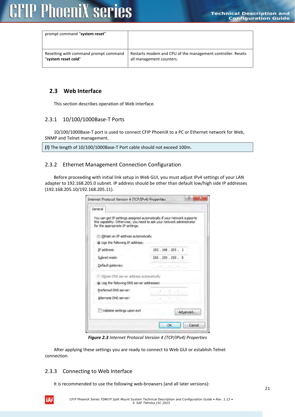
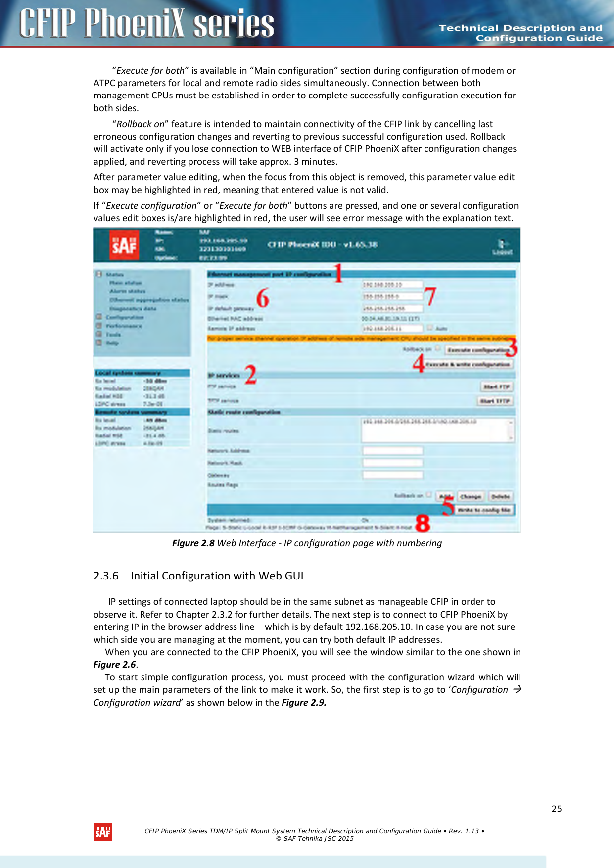
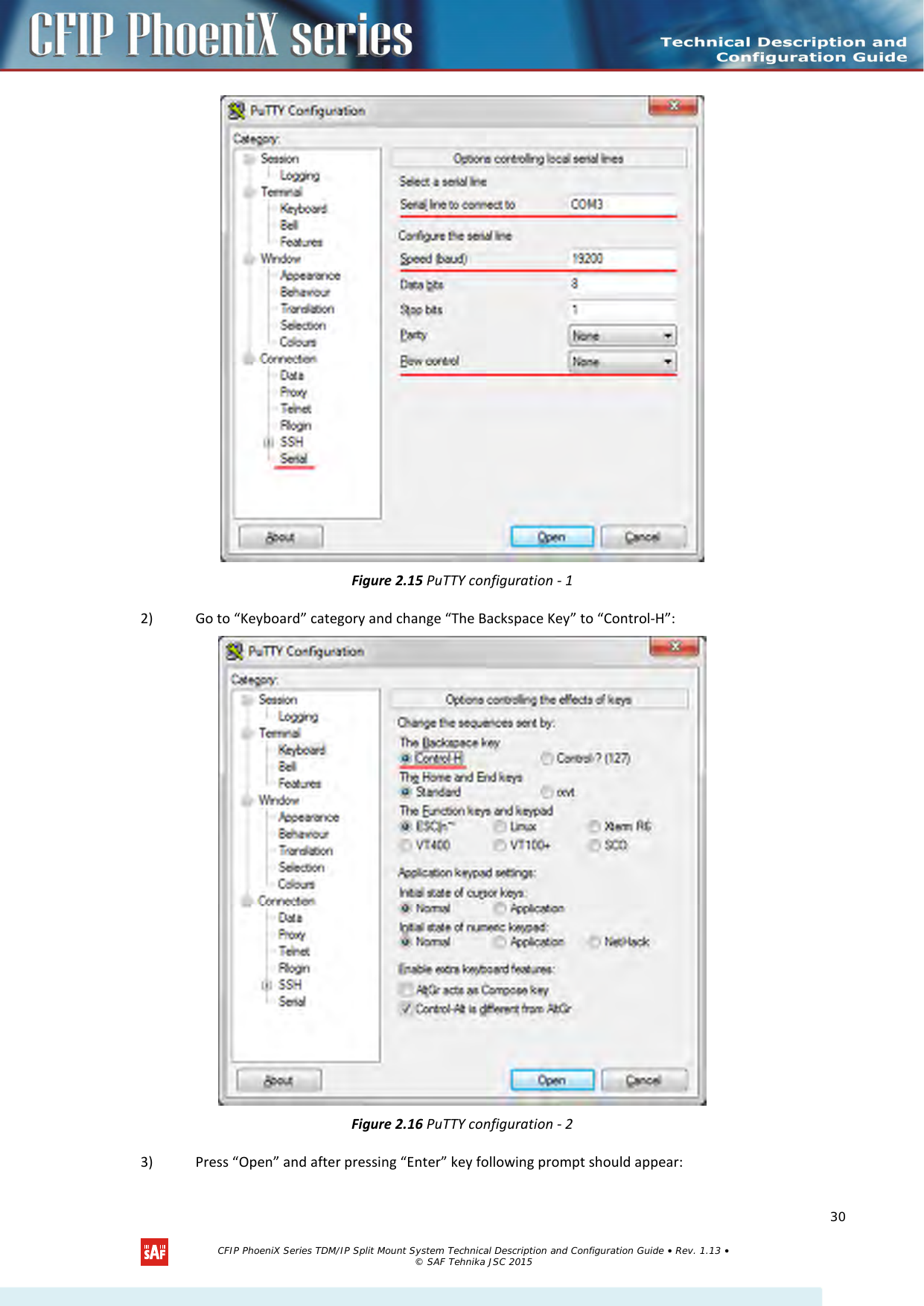
![2.4.1 RS-232 Serial Management Port RS-232 serial management port provides terminal management via a connected PC or another terminal device or modem. The terminal connected to serial management port provides the same management functionality as Telnet interfaces (refer to Chapter 2.3.2). In order to interconnect the CFIP PhoeniX and the management terminal directly through serial ports, a “straight through” modem cable is required. Figure 2.14 Serial connection to CFIP PhoeniX To connect the PC to the RS232 management port, using serial terminal-emulation software (e.g. PuTTY), use the following parameters: • Baud rate: 19200 • Data bits: 8 • Parity: None • Stop bits: 1 • Data flow control: None Below are connection steps with PuTTY - Windows freeware software. 1) Open PuTTY and go to “Serial” category. Specify your COM port number you will be using, change “Speed (baud)” to “19200” and “Flow control” to “None”: (!) Syntactic notes for command prompt commands – Commands are in bold font. – All arguments (variables) are in italic font. – Subcommands and keywords are in regular font. – Arguments in square brackets ([ ]) are optional but required arguments are in angle brackets (<>). – Alternative keywords are grouped in braces ( {} ) and separated by vertical bars ( | ). – The purpose of each command will be displayed if command is typed with “?” at the end (or any unrecognizable string) is entered, e.g., radio ? The management system is automatically restarted if it freezes. This is performed by the watchdog timer. Restart of the management system is not affecting (interrupting) the Ethernet traffic. CFIP PhoeniX Series TDM/IP Split Mount System Technical Description and Configuration Guide • Rev. 1.13 • © SAF Tehnika JSC 2015 29](https://usermanual.wiki/SAF-Tehnika-AS/58F2DMX.User-Manual-1/User-Guide-3623550-Page-29.png)
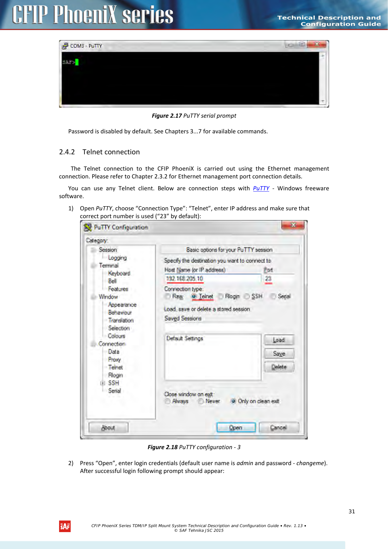
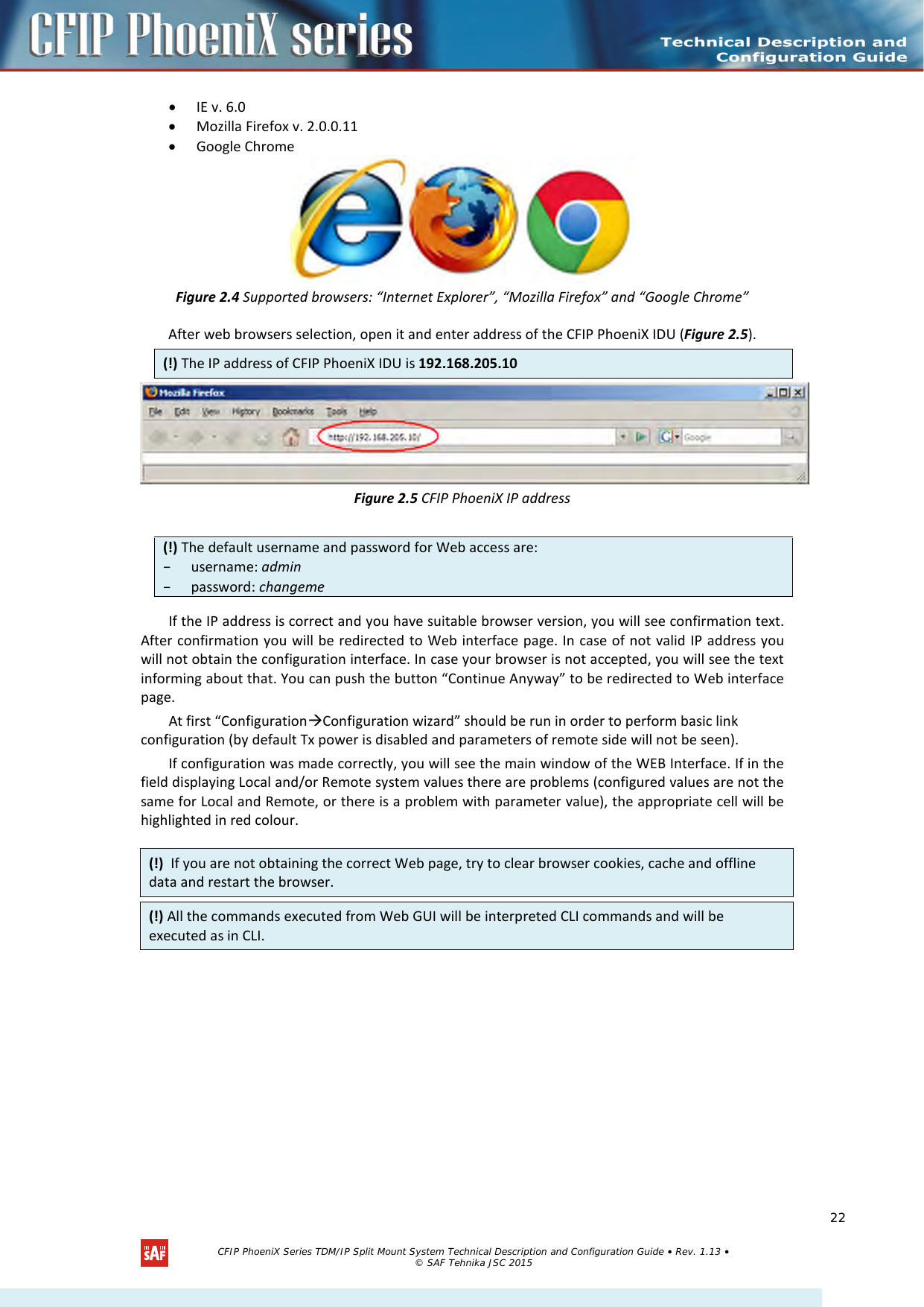
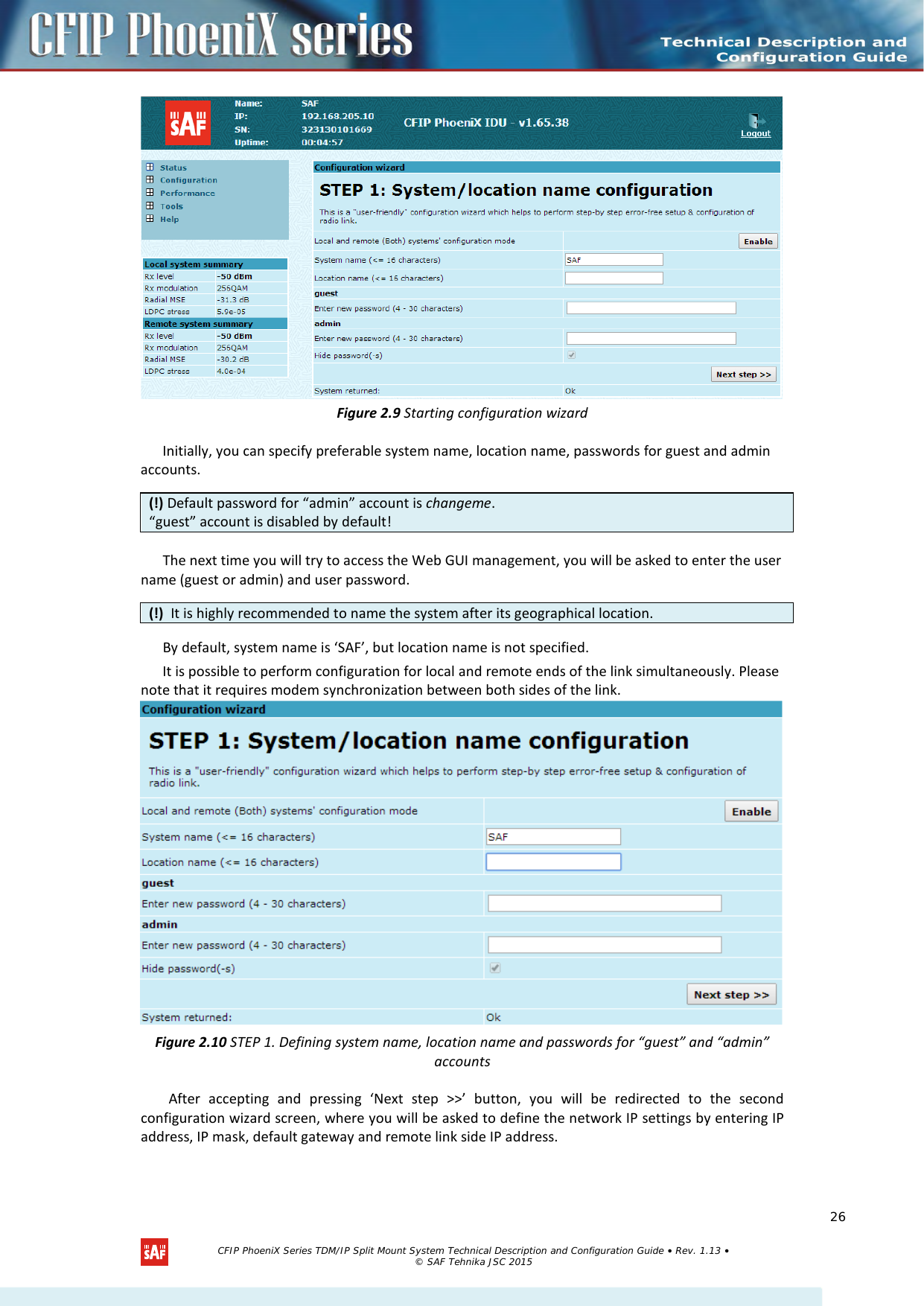
![Figure 2.19 PuTTY Telnet prompt See Chapters 3...7 for available commands. 2.4.3 Initial Configuration with Command Prompt Configuration steps using command prompt are as follows: 1. Check the system settings with command ‘status’ 2. Configuration required parameters: – Tx power with the command ‘radio txpower [<power dBm>]’; – Tx frequency with the command ‘radio freq [<freq KHz>]’; – Channel bandwidth, modulation, FEC mode and channel mask with the command ‘modem set <bandwidth> <min modulation> <max modulation> <WeakFEC|StrongFEC> <channel mask>’, where you can choose among 3.5-56 MHz values and modulations 4QAM – 256QAM; – Name of CFIP PhoeniX with the command ‘system name <name>’. Default name is ‘SAF’; – IP address with the command ‘net ip addr <addr>’, if it is necessary; – IP mask with the command ‘net ip mask <mask>’ , if it is necessary; – IP default gateway with the command ‘net ip gw <gw>’ , if it is necessary; 3. Save settings with the command ‘cfg write’; restarting with the command ‘system reset’; 4. Check the settings made, modem and radio status with the commands ‘status’, ‘modem status’ and ‘radio status’ respectively. 2.5 LED indications 2.5.1 CFIP PhoeniX IDU alarm LED indications Below you can see table summarizing which alarms each of CFIP PhoeniX IDU LEDs represents. (!) Before you set the parameters listed below, you must know what frequency and bandwidth you are allowed to use and at what power you are allowed to transmit. CFIP PhoeniX Series TDM/IP Split Mount System Technical Description and Configuration Guide • Rev. 1.13 • © SAF Tehnika JSC 2015 32](https://usermanual.wiki/SAF-Tehnika-AS/58F2DMX.User-Manual-1/User-Guide-3623550-Page-32.png)
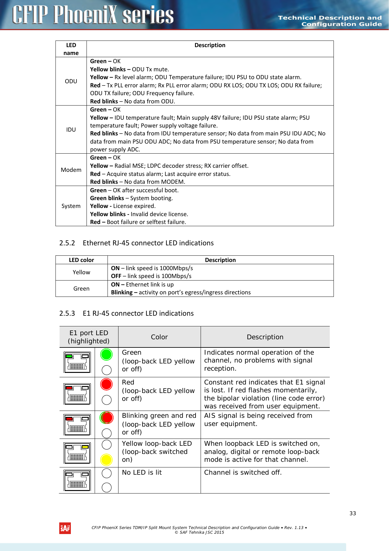
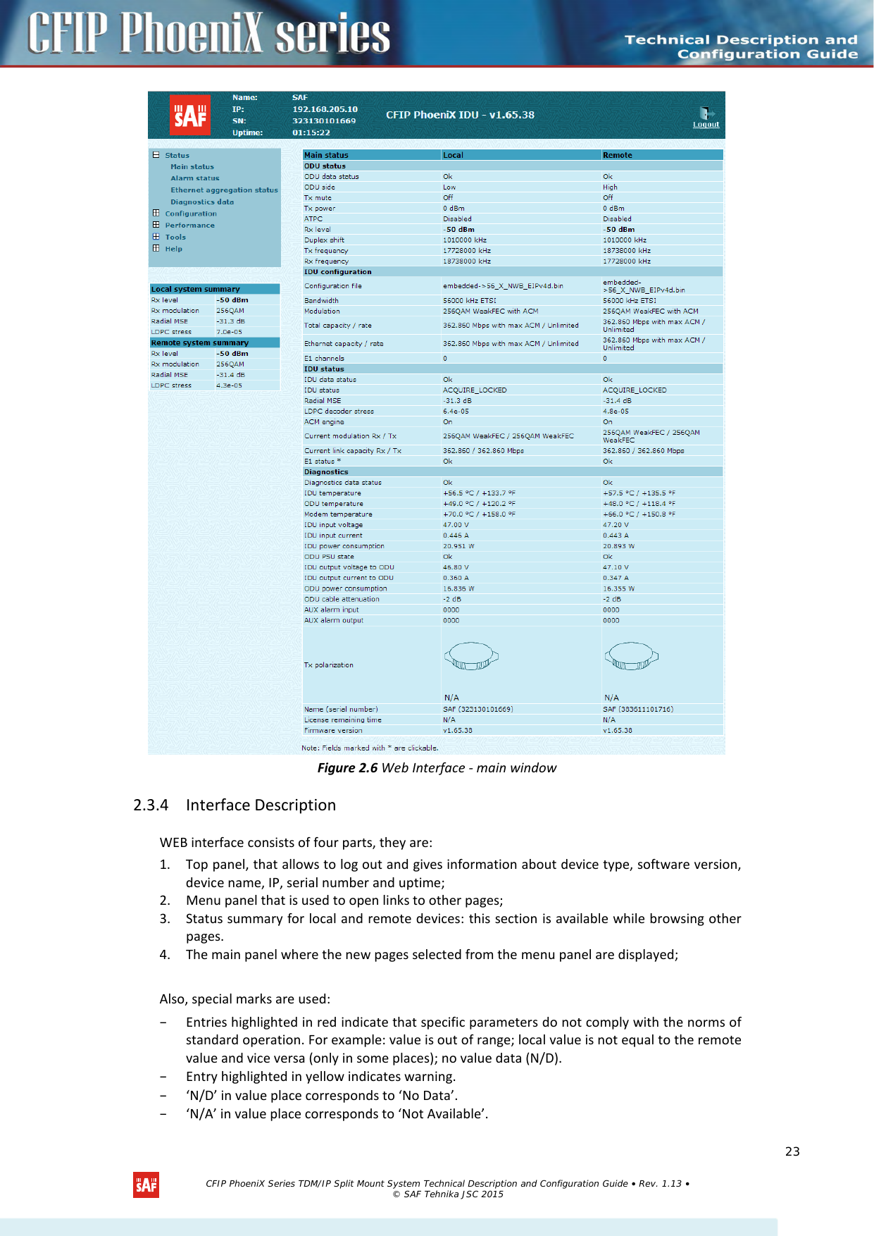
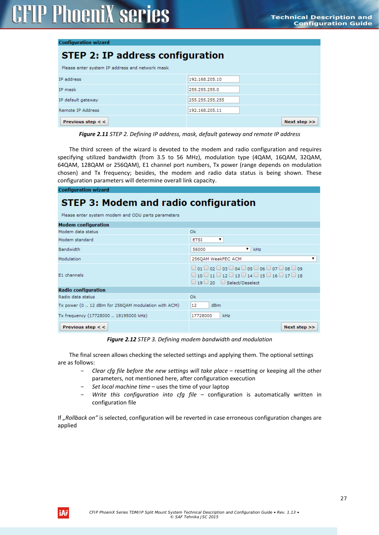
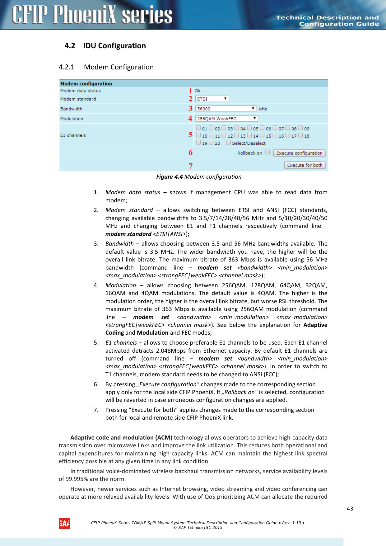
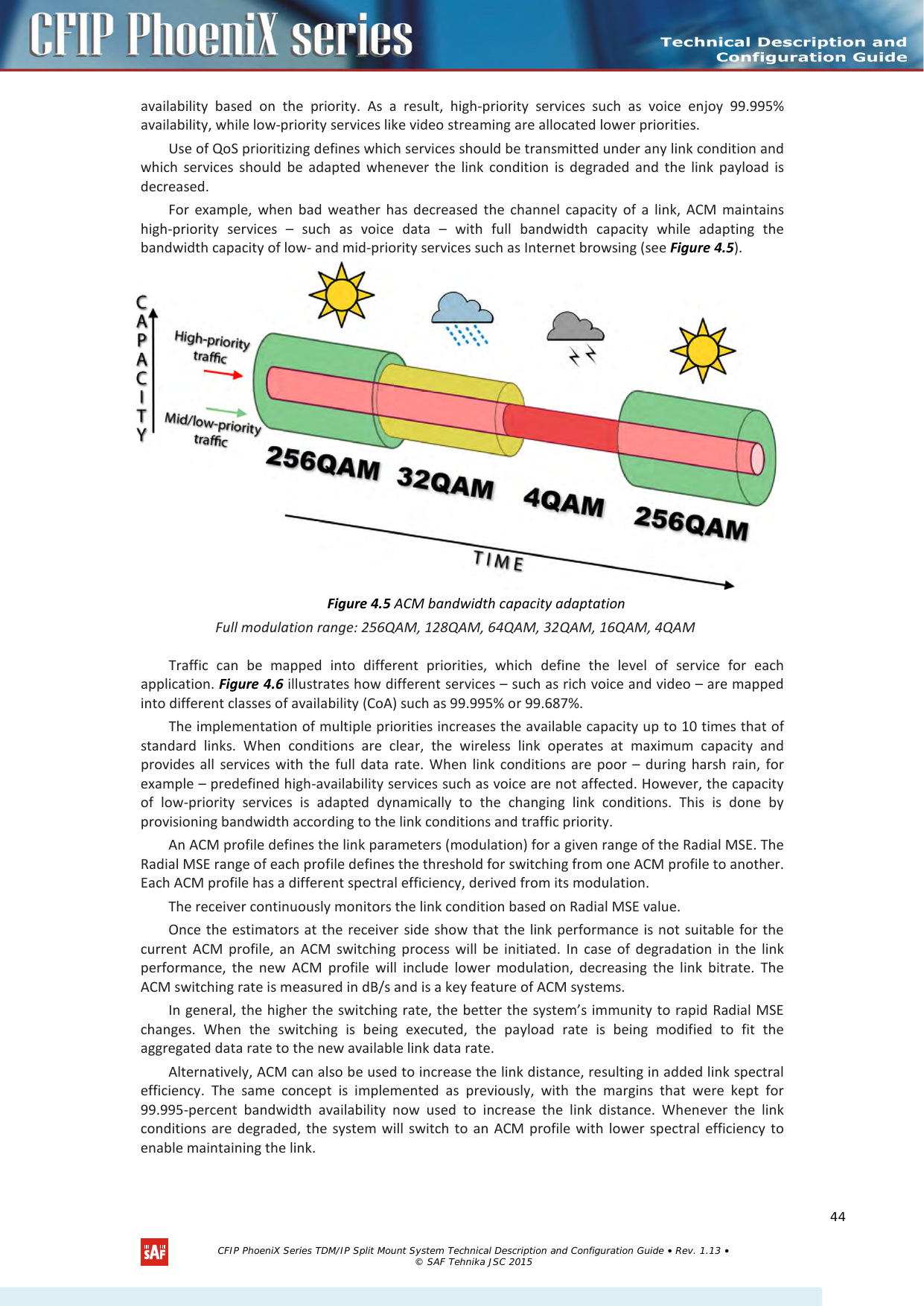
![4 Detailed Configuration in Web Graphic User Interface Configuration section in Web interface allows customizing your system to suit your specific needs. 4.1 ODU Configuration The ODU configuration window provides the configuration of CFIP PhoeniX radio part parameters. Below is a short explanation of provided customization fields. 4.1.1 Radio Configuration Figure 4.1 Radio configuration 1. ODU data status – shows if management CPU was able to read data from the radio; 2. Radio side – shows if radio side you are currently viewing is low or high (command line – radio side); 3. Tx power – allows you to define transmitter power. If the RSL is too high (much higher than normal -50dBm), you might want to lower transmitter power. Too high Rx level (> -20 dBm) may even result in synchronization loss. The minimum and maximal values you can choose are dependent on modulation type and CFIP model. Maximal and minimal Tx power values are shown in the brackets. (command line - radio txpower [<power dBm>]); 4. Tx frequency – allows you to enter preferable transmitter frequency, hence defining utilized channel (command line - radio txfreq [<freq KHz>]); 5. Rx frequency – shows the current receiver utilized frequency (command line - radio freq); 6. Duplex shift – shows the duplex shift between the transmitter frequency and receiver frequency (command line - radio duplexshift); 7. Tx mute – allows turning transmitter power off. It may be effective when diagnosing on interference existence – when transmitter power of one side is off, you should not experience significant RSL on the other side (command line - radio txmute [on|off]); 8. By pressing „Execute configuration” changes made to the corresponding section apply only for the local side CFIP PhoeniX. If „Rollback on” is selected, configuration will be reverted in case erroneous configuration changes are applied. 9. Pressing “Execute for both” applies changes made to the corresponding section both for local and remote side CFIP PhoeniX. CFIP PhoeniX Series TDM/IP Split Mount System Technical Description and Configuration Guide • Rev. 1.13 • © SAF Tehnika JSC 2015 40](https://usermanual.wiki/SAF-Tehnika-AS/58F2DMX.User-Manual-1/User-Guide-3623550-Page-40.png)
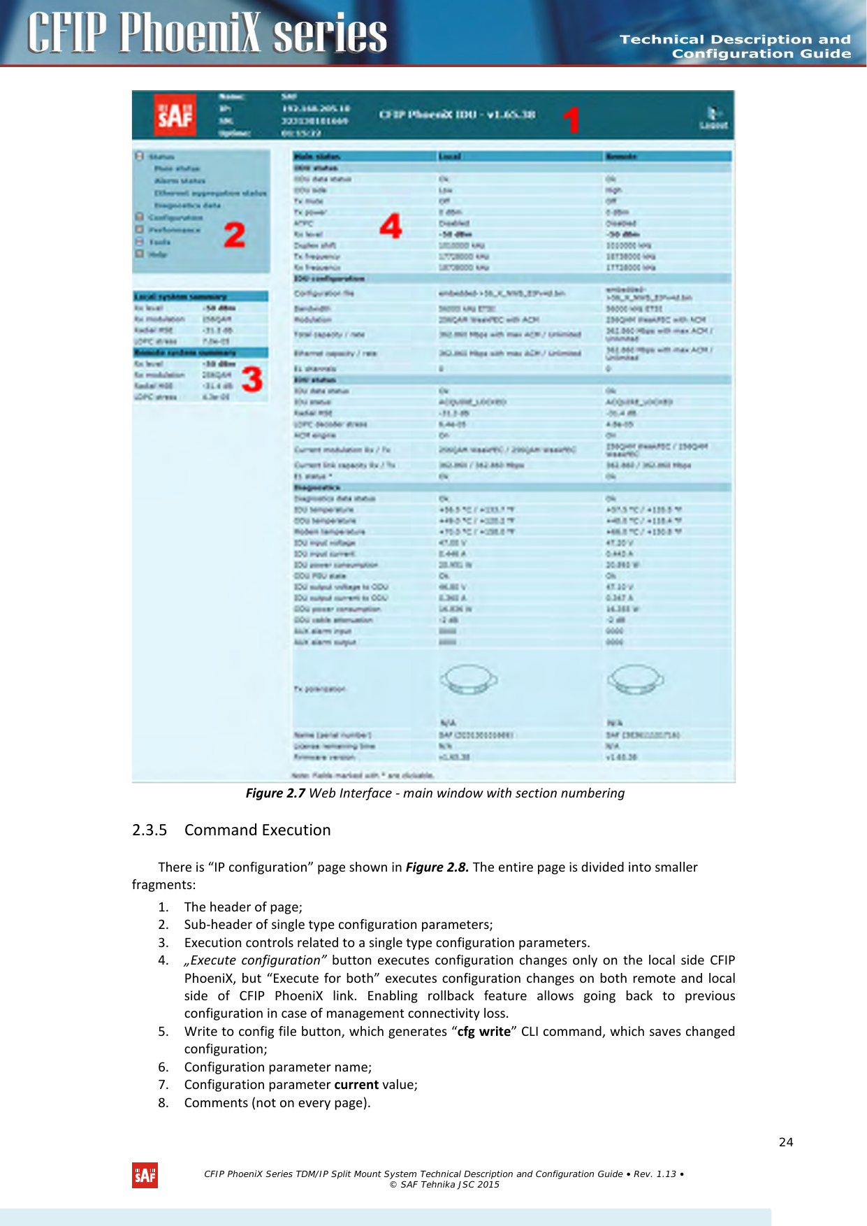
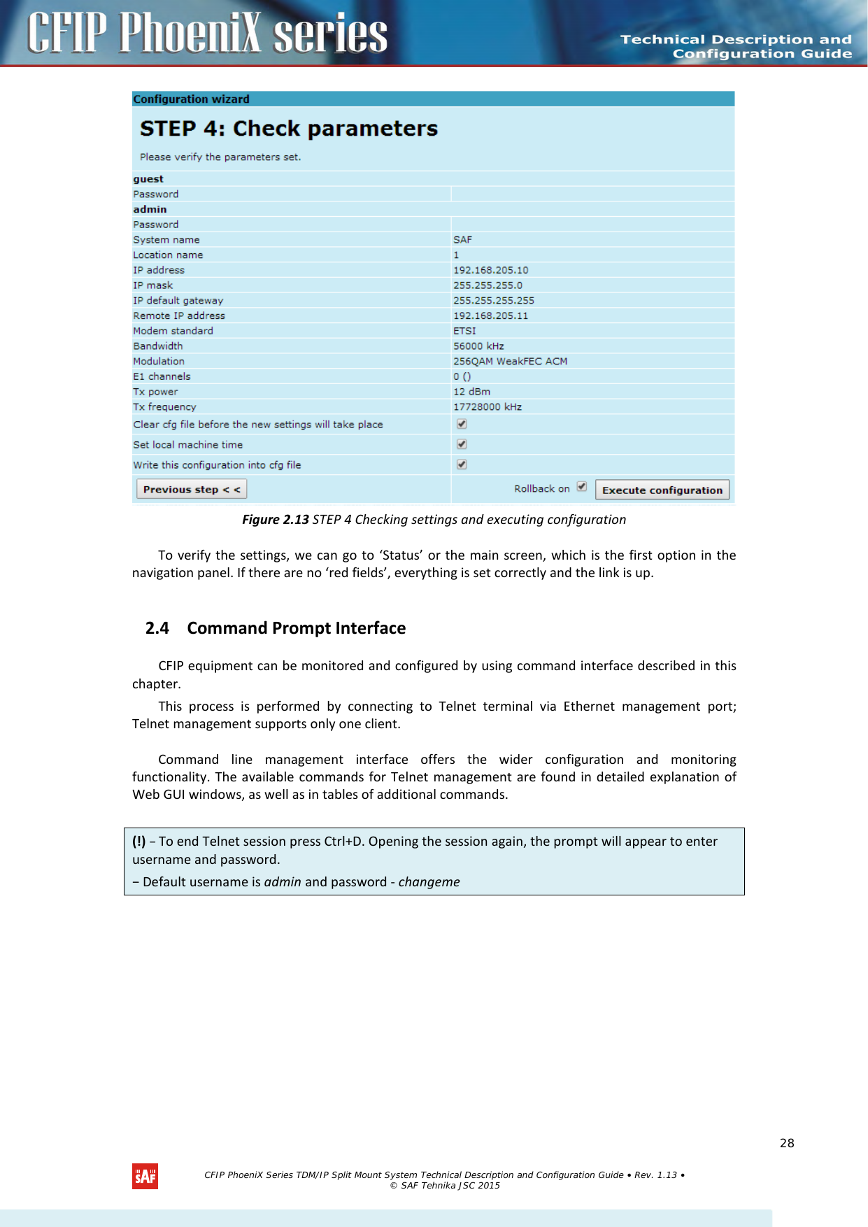
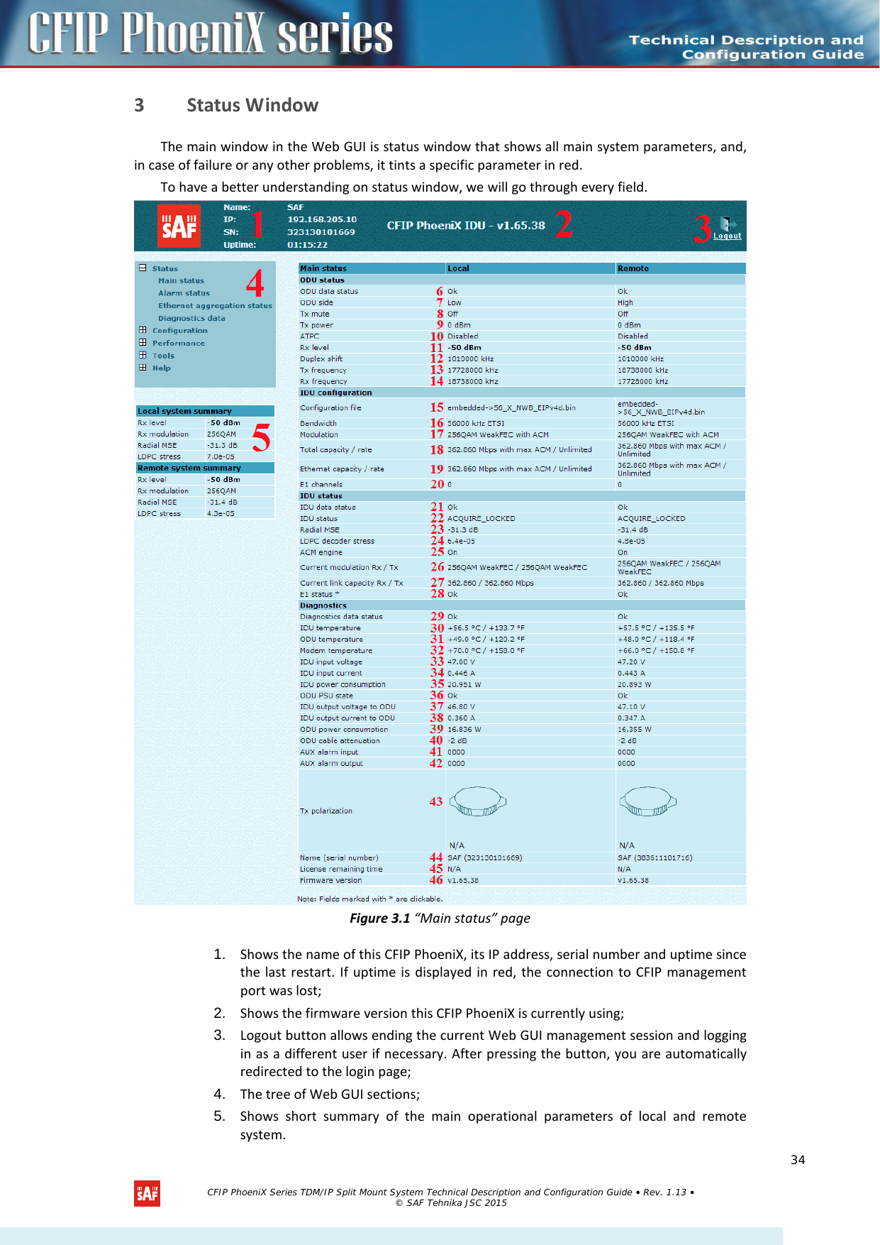
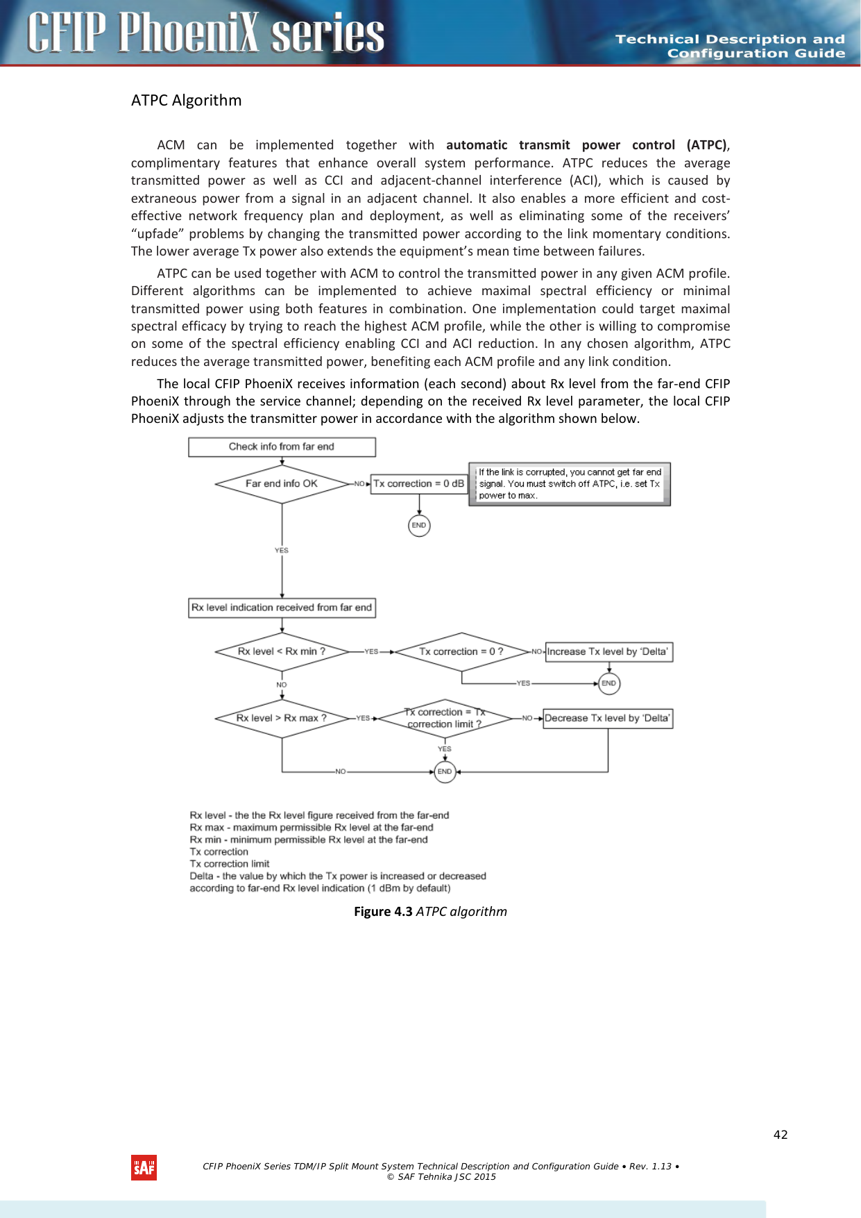
![4.1.2 ATPC Configuration To configure ATPC, it is necessary to set Rx (remote) “min” and “max” values and enable the ATPC feature. ATPC update period and ATPC delta are recommended to be left unchanged. It is also possible to change the limit of Tx power correction. Figure 4.2 ATPC configuration 1. ATPC function – allows enabling or disabling ATPC (Automatic Transmit Power Control). By default this feature is disabled (command line – atpc [enable|disable]); 2. ATPC update period (1..5) – allows defining the period in seconds in which ATPC parameters are being updated. By default the update period is 1 second (command line – atpc delay <power change delay time 1..5 sec>); 3. Tx power correction – displays the amount of transmitter power in decibels ATPC has currently corrected (command line – atpc status); 4. Tx power correction limit – allows defining the amount of dB ATPC will be able to correct regarding initial Tx power value (command line – atpc limit <tx power correction limit>); 5. Remote device status – shows if management CPU was able to read data from remote management CPU; 6. Rx (remote) level (-90..-20 dBm) – allows defining the maximum and minimum Rx level. ATPC Tx power correction will be performed only in case of exceeding these defined thresholds Rx level (command line – atpc rxminmax <rxmin> <rxmax>); 7. Rx (remote) level – shows current Rx level of remote end (command line – atpc status); 8. By pressing „Execute configuration” changes made to the corresponding section apply only for the local side CFIP PhoeniX. If “Rollback on” is selected, configuration will be reverted in case erroneous configuration changes are applied. 9. Pressing “Execute for both” applies changes made to the corresponding section both for local and remote side CFIP PhoeniX. 10. Pressing “Write to config file” saves all the changes made on the whole page (command line – cfg write); 11. Pressing “Write to config file for both” saves all the changes made on the whole page for both ends of the link simultaneously (command line – cfg write); 12. System returned - in case of error or incorrectly entered parameter value, or other problems on the whole page – the info message is being shown here. Otherwise it says “Ok”. (!) Note, that ATPC is mechanism for reducing Tx power, that’s why to make proper use of ATPC, transmitter power (Tx power) must be set to the maximum value. CFIP PhoeniX Series TDM/IP Split Mount System Technical Description and Configuration Guide • Rev. 1.13 • © SAF Tehnika JSC 2015 41](https://usermanual.wiki/SAF-Tehnika-AS/58F2DMX.User-Manual-1/User-Guide-3623550-Page-41.png)
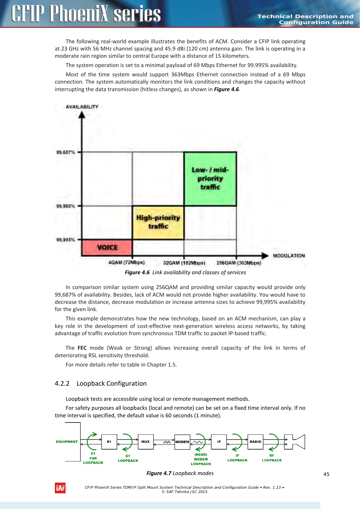
![• E1 and E1 FAR loopback modes loop signal back to local end and to remote end respectively in bounds of E1 interface. E1 loopback mode must be set on the particular channel you need to test. If no E1 channels are selected, E1 loopback mode is not available. E1 loopbacks are named “interface” and “interface far” in “Loopback name” dropdown menu. • MODEM loopback mode loops signal back to local end after the modem. • IF loopback mode loops signal back to local end by linking intermediate frequencies. Figure 4.8 Loopback configuration 1. Loopback name – allows choosing loopback mode (command line – loopback {status | none | if | modem |e1 <num> [far] | e1 mask <mask> [far]} [<time>]); 2. Loopback timeout – allows specifying activity time of chosen loopback mode in seconds (command line – loopback {status | none | if | modem |e1 <num> [far] | e1 mask <mask> [far]} [<time>]); 3. By pressing „Execute configuration” changes made to the corresponding section apply only for the local side CFIP PhoeniX. If „Rollback on” is selected, configuration will be reverted in case erroneous configuration changes are applied. 4. Pressing “Write to config file” saves all changes made in the whole page (command line – cfg write); 5. Pressing “Write to config file for both” saves all changes made in the whole page for both sides of the link simultaneously (command line – cfg write); 6. System returned - in case of error or incorrectly entered parameter value, or other problems in the whole page – info message will be displayed here. Otherwise it says “Ok”. Additional radio and modem configuration commands in Telnet/serial interface Command Description modem status Shows all the modem parameters. modem configuration show Displays current configuration file. modem configuration <file> Uses separate configuration file. modem configuration embedded Switches back to the embedded configuration last used. modem factory [max] Resets modem settings to factory defaults (minimum bandwidth, minimum modulation). ‘max’ option will set maximum configuration (maximum bandwidth, maximum modulation + ACM). modem ipremote [on | off] Allows enabling manual remote IP specifying (modem ipremote off). By default remote IP is being obtained automatically (modem ipremote on). modem standard [etsi | ansi] Allows switching between ETSI and ANSI (FCC) standards, allowing to utilize E1 channels or T1 channels respectively. modem counters [show | clear] Shows modem performance counters according to G.826 standard. radio factory [max] Resets radio settings to factory defaults. By default Tx power will be turned off. ‘max’ option will switch Tx power to the maximum value after restart. radio duplexshift [<DS KHz>] Allows switching to different duplexshift if supported. radio side [L|H] Allows switching radio side if supported. CFIP PhoeniX Series TDM/IP Split Mount System Technical Description and Configuration Guide • Rev. 1.13 • © SAF Tehnika JSC 2015 46](https://usermanual.wiki/SAF-Tehnika-AS/58F2DMX.User-Manual-1/User-Guide-3623550-Page-46.png)
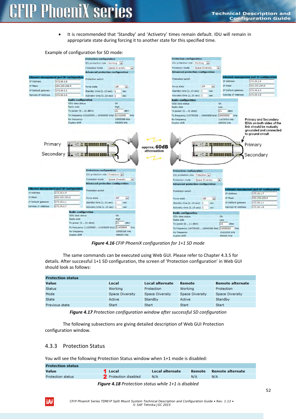
![1. Value – denotes the names of CFIP PhoeniX units in 1+1 configuration. ‘Local’ and ‘Local alternate’ designates both units (working and protection) at the local side and ‘Remote’ and ‘Remote alternate’ designates both units of remote side. 2. Protection status – denotes that CFIP PhoeniX 1+1 protection is disabled. In case 1+1 Hot Standby mode is enabled the Protection Status window might look as follows: Figure 4.19 Protection status while 1+1 is enabled 1. Status – for enabled 1+1 protection mode designates the status of each CFIP Phoenix unit in 1+1 protection mode. ‘Working’ denotes that particular unit is used for main working link and ‘Protection’ designates that particular unit is used for protection purpose. 2. Mode – specifies the 1+1 protection mode. Possible modes are ‘Hot Standby’ or ‘Frequency Standby’ 3. State – designates the state of each unit specifically for Hot Standby mode. ‘Active’ designates that CFIP PhoeniX unit is active part of 1+1 Hot Standby mode and ‘Standby’ state denotes that unit is on standby. 4. Previous state – denotes the previous state of each CFIP PhoeniX unit in 1+1 protection mode 4.3.4 Protection Configuration Figure 4.20 Protection configuration 1. IDU protection role – allows specifying the protection role of CFIP PhoeniX IDU from drop-down menu. Available roles are ‘Working’, ‘Protection’ or ‘Disable’ that allows disable the protection role of IDU (command line – prot set {hsb|fd} {working|protection|disable} [independent]); 2. Protection mode – gives the possibility to choose ‘Hot Standby’ or ‘Frequency Diversity’ protection mode from the drop-down menu (command line – prot set {hsb|fd} {working|protection|disable} [independent]); 3. By pressing „Execute configuration” changes made to the corresponding section apply only for the local side CFIP PhoeniX. If „Rollback on” is selected, configuration will be reverted in case erroneous configuration changes are applied. 4.3.5 Advanced Protection Configuration The following section will appear in Web GUI only if protection is enabled for 1+1 Hot Standby mode. CFIP PhoeniX Series TDM/IP Split Mount System Technical Description and Configuration Guide • Rev. 1.13 • © SAF Tehnika JSC 2015 53](https://usermanual.wiki/SAF-Tehnika-AS/58F2DMX.User-Manual-1/User-Guide-3623550-Page-53.png)
![Figure 4.21 Advanced protection configuration 1. Protection switch – temporarily switches IDU to active or standby state (command line – prot {active|standby}); 2. Force state – permanently switches IDU to active or standby state until force state is disabled by selecting ‘Off’ (command line – prot force {active|standby|off}); 3. Standby time – allows specifying Standby time (in range 1 – 15sec) for Standby state. IDU will remain for this time slot in Standby state during forcing it to another state (command line – prot time standby [<0...15 sec.>]); 4. Activetry time – allows specifying Active try time (in range 1-15sec) for Activetry state. IDU will remain for this time slot in Activetry state during forcing it to another state (command line – prot time activetry [<0...15 sec.>]); 5. By pressing „Execute configuration” changes made to the corresponding section apply only for the local side CFIP PhoeniX. If „Rollback on” is selected, configuration will be reverted in case erroneous configuration changes are applied. 6. Writes to configuration file all the changes made on the whole page (command line – cfg write); 7. System returned - in case of error or incorrectly entered parameter value, or other problems on the whole page – info message will be displayed here. Otherwise it says “Ok”. 4.4 System Configuration The system configuration window provides the configuration of web access, telnet and FTP interfaces; allows changing system name, web data refresh time and system time. Additional user management commands in Telnet/serial interface Command Description prot status [remote|alternate|altrem|all] Shows protection status of particular IDU, as well as of any or all units involved in 1+1 configuration prot alarms Shows protection alarm status prot trace Traces protection state changes by printouts on terminal prot ext statistics Shows protection information exchange quality statistics between local and alternate IDU prot ext statistics clear Clears all previous exchange quality statistics CFIP PhoeniX Series TDM/IP Split Mount System Technical Description and Configuration Guide • Rev. 1.13 • © SAF Tehnika JSC 2015 54](https://usermanual.wiki/SAF-Tehnika-AS/58F2DMX.User-Manual-1/User-Guide-3623550-Page-54.png)
![4.4.1 User Configuration Figure 4.22 User configuration 1. guest – Enter new password (length: 4..30 characters) – allows entering preferable ‘guest’ account password and enabling the account. By default guest account is disabled. Maximal length of the password cannot exceed 30 symbols. Guest account has only monitoring privileges. The following Web GUI sections are available: Figure 4.23 Menu for “guest” user 2. admin – Enter new password (length: 4..30 characters) – allows to enter preferable ‘admin’ account password. Maximal length of user name cannot exceed 30 symbols. By default password for ‘admin’ account is ‘changeme’. Admin account has full control of the CFIP configuration process. 3. Hide password(-s) – Hides typed in password. This option unchecked will display typed in password in plaintext. 4. By pressing “Execute configuration” changes made to the corresponding section apply only for the local side CFIP PhoeniX. If “Rollback on” is selected, configuration will be reverted in case erroneous configuration changes are applied. More detailed status controls are available in command prompt, which include: Additional user management commands in Telnet/serial interface Command Description access login <name> <password> Logs on as a user specified by <name> and <password>. access logout Logs current user out. access set <guest|admin> <password> [plaintext] Allows specifying a new password for a specific account (admin or guest). ‘plaintext’ option will save the password in plaintext in configuration script without encrypting it (by default saved passwords in configuration file are encrypted). access show Shows user name and password of a user currently logged on. access list Shows the list of usernames and passwords the current account is able to manage (if logged on as admin, ‘guest’ and ‘admin’ account passwords will be seen). CFIP PhoeniX Series TDM/IP Split Mount System Technical Description and Configuration Guide • Rev. 1.13 • © SAF Tehnika JSC 2015 55](https://usermanual.wiki/SAF-Tehnika-AS/58F2DMX.User-Manual-1/User-Guide-3623550-Page-55.png)
![4.4.2 Name configuration Figure 4.24 Name configuration 1. System name (Max length: 16 characters) – allows entering preferable system name. Maximum length of the system name cannot exceed 16 symbols. Default name is ‘SAF’ (command line – system name <name>); 2. Location name (Max length: 16 characters) – allows entering preferable system location name. Maximum length of the location name cannot exceed 16 symbols. By default system location is not specified (command line – system location <name>); 3. System hostname (Max length: 16 characters) – allows entering preferable system hostname. Maximum length of the hostname cannot exceed 16 symbols. By default system location is not specified (command line – system location <name>); 4. Pressing „Execute configuration” applies changes made to the corresponding section only for the local side CFIP PhoeniX. If „Rollback on” is selected, configuration will be reverted in case of erroneous configuration changes applied. 4.4.3 Other configuration Figure 4.25 Other configuration 1. Web refresh (2 .. 600 sec) – allows specifying time interval of Web data refreshing. The default value is 5 seconds. You can choose between 2 and 600 seconds (10 minutes) (command line – web refresh <web refresh time>); 2. Time (Usage: YY-MM-DD HH:mm:ss) – allows changing system date and time manually by entering date and time in specific syntax. “Set local machine time” button forces system to use the time set on your PC or laptop, from which you are connected to the Web interface (command line – system time [yyyy-mm-dd hh:mm:ss]); 3. By pressing “Execute configuration” changes made to the corresponding section apply only for the local side CFIP PhoeniX. If “Rollback on” is selected, configuration will be reverted in case erroneous configuration changes are applied. 4.4.4 NTP configuration Starting from firmware version 1.64.xx CFIP PhoeniX features NTP (Network Time protocol) implementation – SNTP (Simple Network Time Protocol). CFIP PhoeniX Series TDM/IP Split Mount System Technical Description and Configuration Guide • Rev. 1.13 • © SAF Tehnika JSC 2015 56](https://usermanual.wiki/SAF-Tehnika-AS/58F2DMX.User-Manual-1/User-Guide-3623550-Page-56.png)
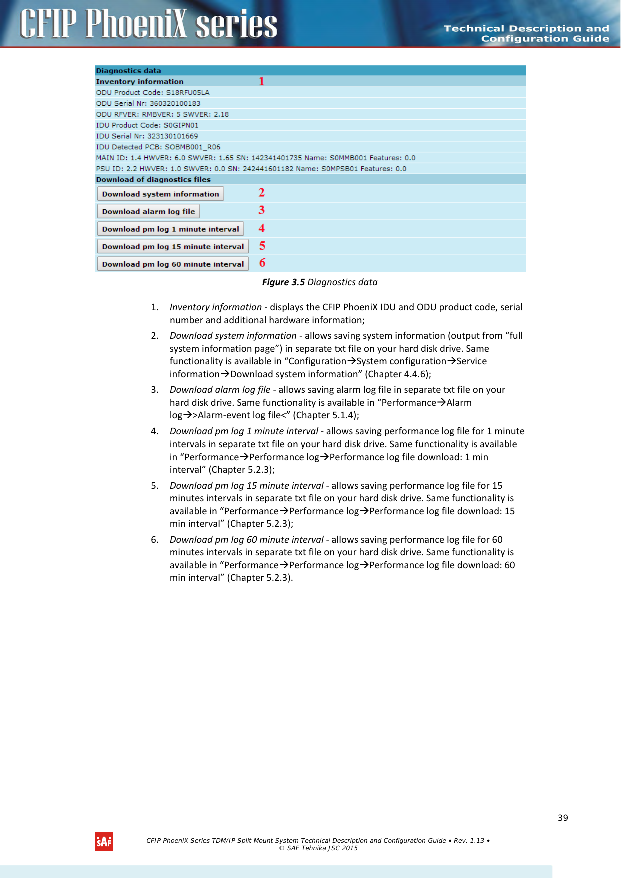
![Figure 4.26 NTP configuration 1. NTP Status – shows if NTP is enabled or disabled (command line – system ntp status); 2. NTP enable – allows enabling or disabling NTP. By default this feature is disabled (command line – system ntp [enable|disable]); 3. NTP server IP address – allows to specify NTP server IP address (command line – system ntp server <IP address>); 4. NTP time zone (-12..12) – allows to specify UTC (Coordinated Universal Time) offset (command line – system ntp timezone <UTC offset>); 5. By pressing „Execute configuration” changes made to the corresponding section apply only for the local side CFIP PhoeniX. If „Rollback on” is selected, configuration will be reverted in case erroneous configuration changes are applied; 6. Writes to configuration file all the changes made on the whole page (command line – cfg write); 4. Restarts CFIP PhoeniX you are connected to (command line – system reset). 7. 4.4.5 Upgrade Software Figure 4.27 Upgrade software 1. Choose file – allows choosing location of software upgrade file (e.g. cfipidu165.elf.ezip) stored on your hard disk. Software upgrade file must have *.elf.ezip extension. 4.4.6 Service information Figure 4.28 Service information 1. Open full system information page / Download system information – allows to open/save full system information page. Links on the top of the page allow you to save full system information page and alarm log in separate txt files on your hard disk drive; (!) Note that after restarting the CFIP will use only those settings, which are written to the configuration script. Other settings will be set to default values. CFIP PhoeniX Series TDM/IP Split Mount System Technical Description and Configuration Guide • Rev. 1.13 • © SAF Tehnika JSC 2015 57](https://usermanual.wiki/SAF-Tehnika-AS/58F2DMX.User-Manual-1/User-Guide-3623550-Page-57.png)
![2. Open advanced ethernet information page / Download ethernet statistics – allows to open/save advanced Ethernet statistics. Link on the top of the page allow you to save advanced Ethernet statistics page in separate txt file on your hard disk drive; 3. System returned - in case of error or incorrectly entered parameter value, or other problems in the whole page – the info message will be displayed here. Otherwise it says “Ok”. 4.5 IP Configuration Window The IP configuration window provides configuration of the Ethernet management port addressing, IP services and routes. Settings listed here are essential for building a network or other specific traffic purposes. (!) Note that Advanced Ethernet information page resets all counters and gathers Ethernet information. Please wait until information is gathered and displayed. Additional system commands in Telnet/serial interface Command Description System status Displays the name of the device and its uptime. System inventory [ show ] Displays the CFIP PhoeniX product code, serial number and additional information. System aliases [ list | all | basic | off | add | remove | clear ] list – shows the alias list and whether the aliases are going to be used. The user can choose whether to see all the aliases (adding the argument “all”), built-in aliases (“built-in”), or optional aliases (“optional”) , or user aliases (“user”); all – all the aliases will be used; basic – only basic (built-in, hidden and user) aliases will be used; off – no aliases will be used; add – if two arguments are given, creates an alias of the second argument, named as the first argument. If one argument given, alias command tries and loads the aliases from a file specified by the argument; remove – removes the alias specified by the argument; clear – removes all the user aliases. System commands [ show | help ] show – displays all available commands; help – displays available help messages for all commands. System reset [cold] Restarts CPU of the management controller. Resets all management counters. cold – Restarts modem as well. Ver Displays hardware and software version of CFIP-IDU-PhoeniX, as well as built date. CFIP PhoeniX Series TDM/IP Split Mount System Technical Description and Configuration Guide • Rev. 1.13 • © SAF Tehnika JSC 2015 58](https://usermanual.wiki/SAF-Tehnika-AS/58F2DMX.User-Manual-1/User-Guide-3623550-Page-58.png)
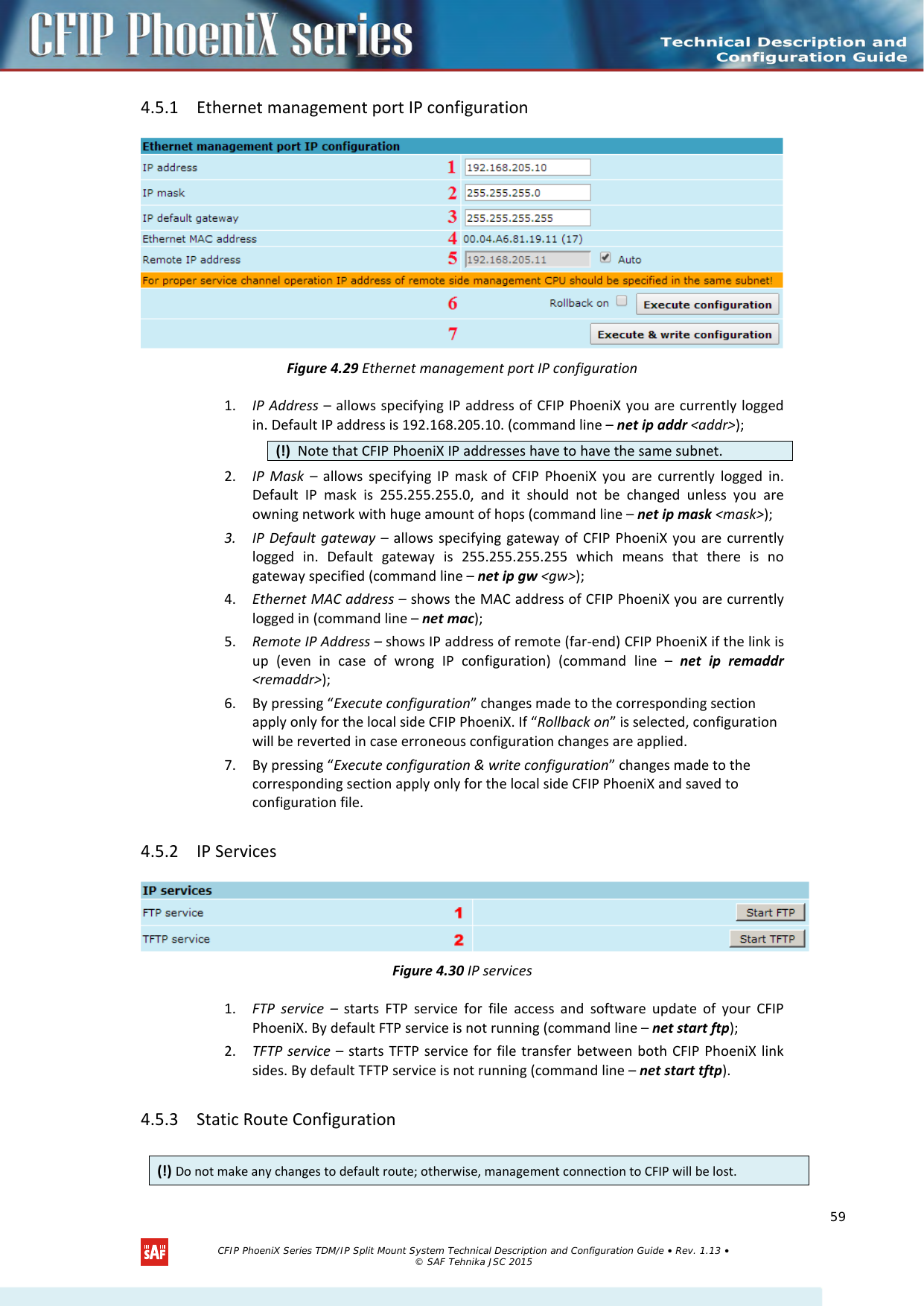
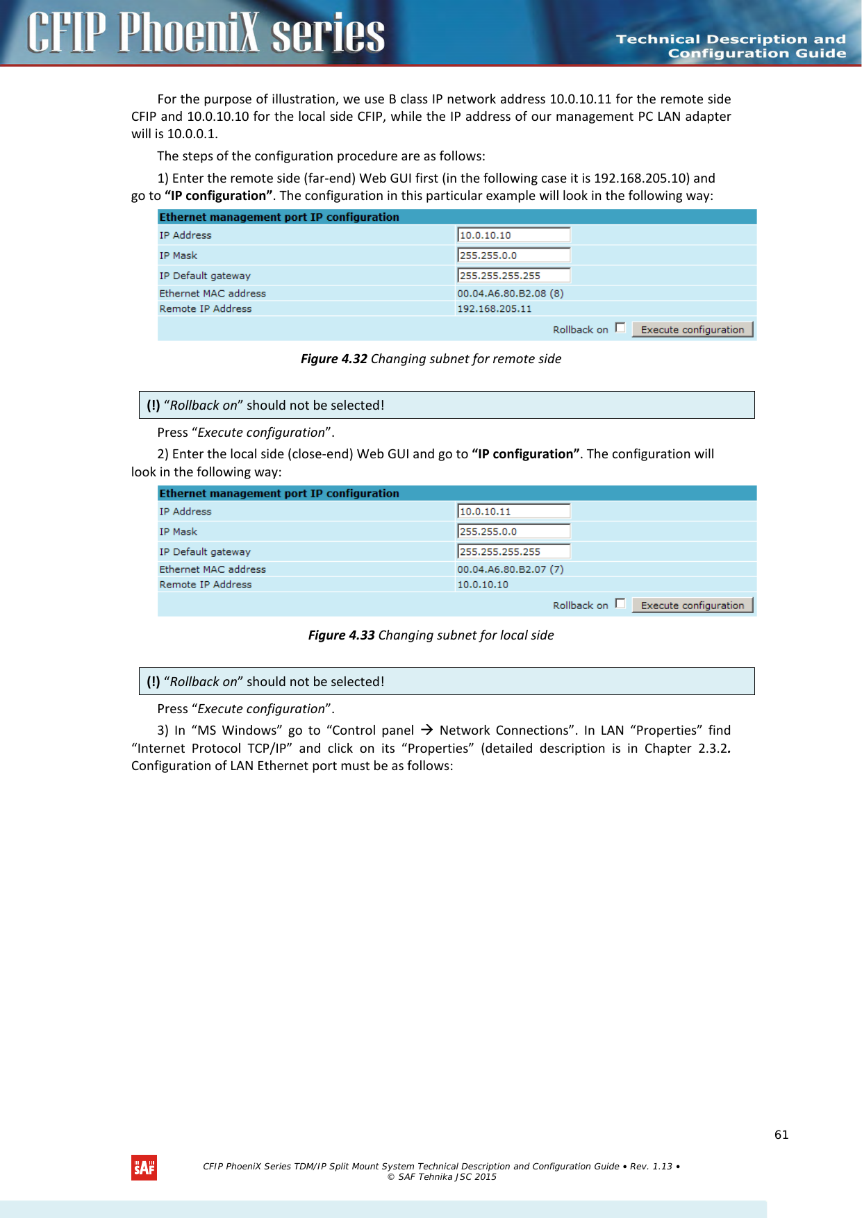
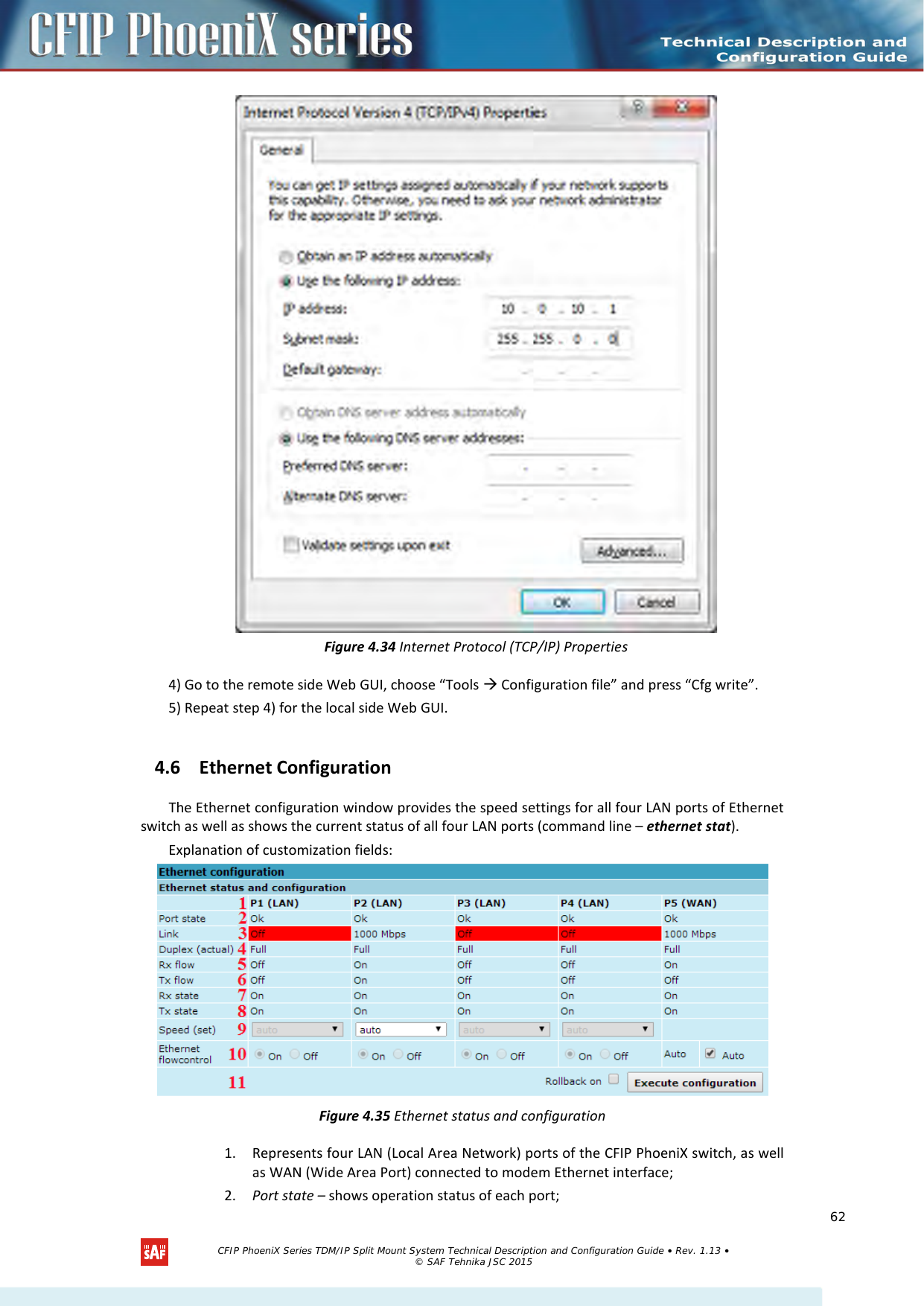
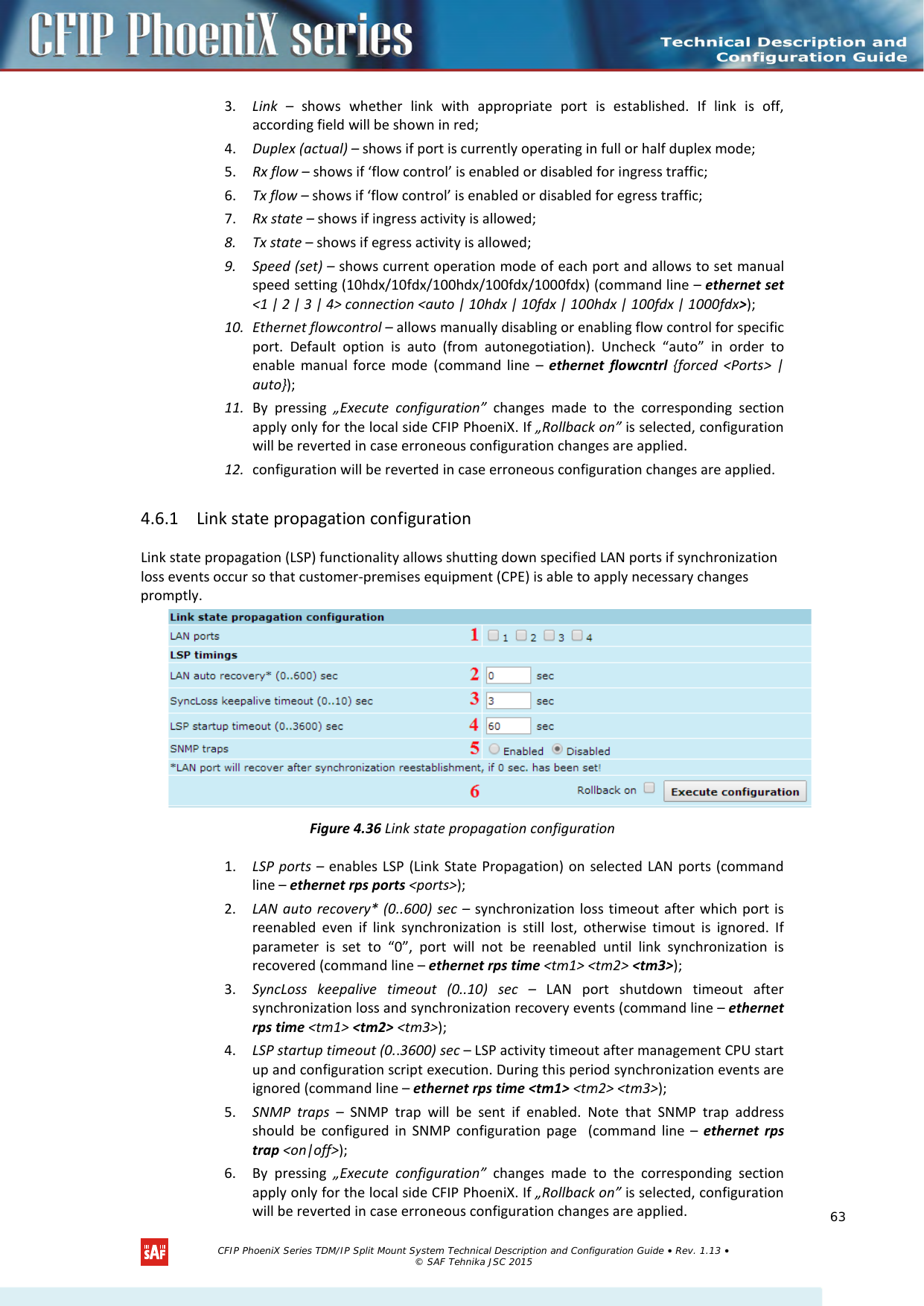
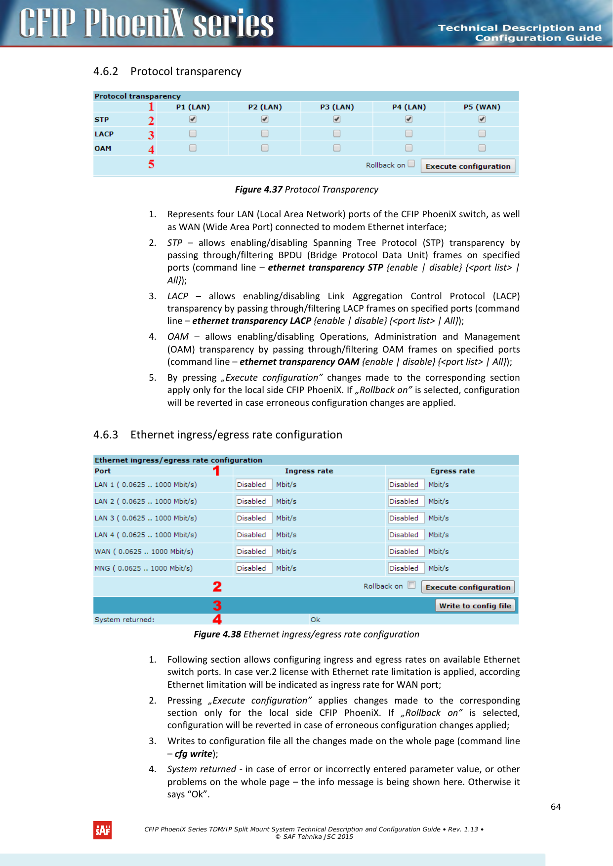
![Figure 4.31 Static route configuration 1. Static routes – shows the list of existing static routes, as well as allows you to choose specific route you are willing to change or delete. By default there is one route which depends on earlier entered IP settings (command line – net route); 2. Network address – allows specifying network address for the route changing/adding (command line – net route add|delete <dest addr> [MASK <mask>] <gateway>); 3. Network mask - allows specifying network mask for changing/adding the route (command line – net route add|delete <dest addr> [MASK <mask>] <gateway>); 4. Gateway - allows specifying gateway for the route changing/adding (command line – net route add|delete <dest addr> [MASK <mask>] <gateway>); 5. After entering addresses or selecting a specific route, buttons “Add”, “Change” and “Delete” allow you to modify CFIP PhoeniX routes. If „Rollback on” is selected, configuration will be reverted in case of erroneous configuration changes applied. 6. Writes to configuration file all the changes made on the whole page (command line – cfg write); 7. System returned - in case of error or incorrectly entered parameter value, or other problems on the whole page – info message will be displayed here. Otherwise it says “Ok”. Below is the explanation of the procedure of network IP configuration in case of network IP Class area change. Additional network configuration commands in Telnet/serial interface Command Description Net ping <ip> This command is for troubleshooting purposes to verify the service channel connectivity, - it sends a special packet to the specified address and then waits for a reply. Net telnet <host> [<port>] Opens Telnet session with the CFIP PhoeniX IDU, host – IP address of the IDU unit management Ethernet port. Net tftp <host> {get|put} <source> [<destination>] Uploads or downloads (put/get) file (<source>) to or from the host IDU unit (<host>). Web trace {show|on|off} Web trace allows you to see commands being executed through Web interface when you’re using serial or telnet connection. Show – shows web trace status (on or off), on – turns web trace on, off – turns web trace off. Web timeout <time in minutes> Allows setting the time, after which the Web GUI presumes no connectivity state. By default the value is set to 15 minutes. Web alert <on|off> Allows to enable or disable Web connectivity alert when Web GUI becomes unreachable CFIP PhoeniX Series TDM/IP Split Mount System Technical Description and Configuration Guide • Rev. 1.13 • © SAF Tehnika JSC 2015 60](https://usermanual.wiki/SAF-Tehnika-AS/58F2DMX.User-Manual-1/User-Guide-3623550-Page-60.png)
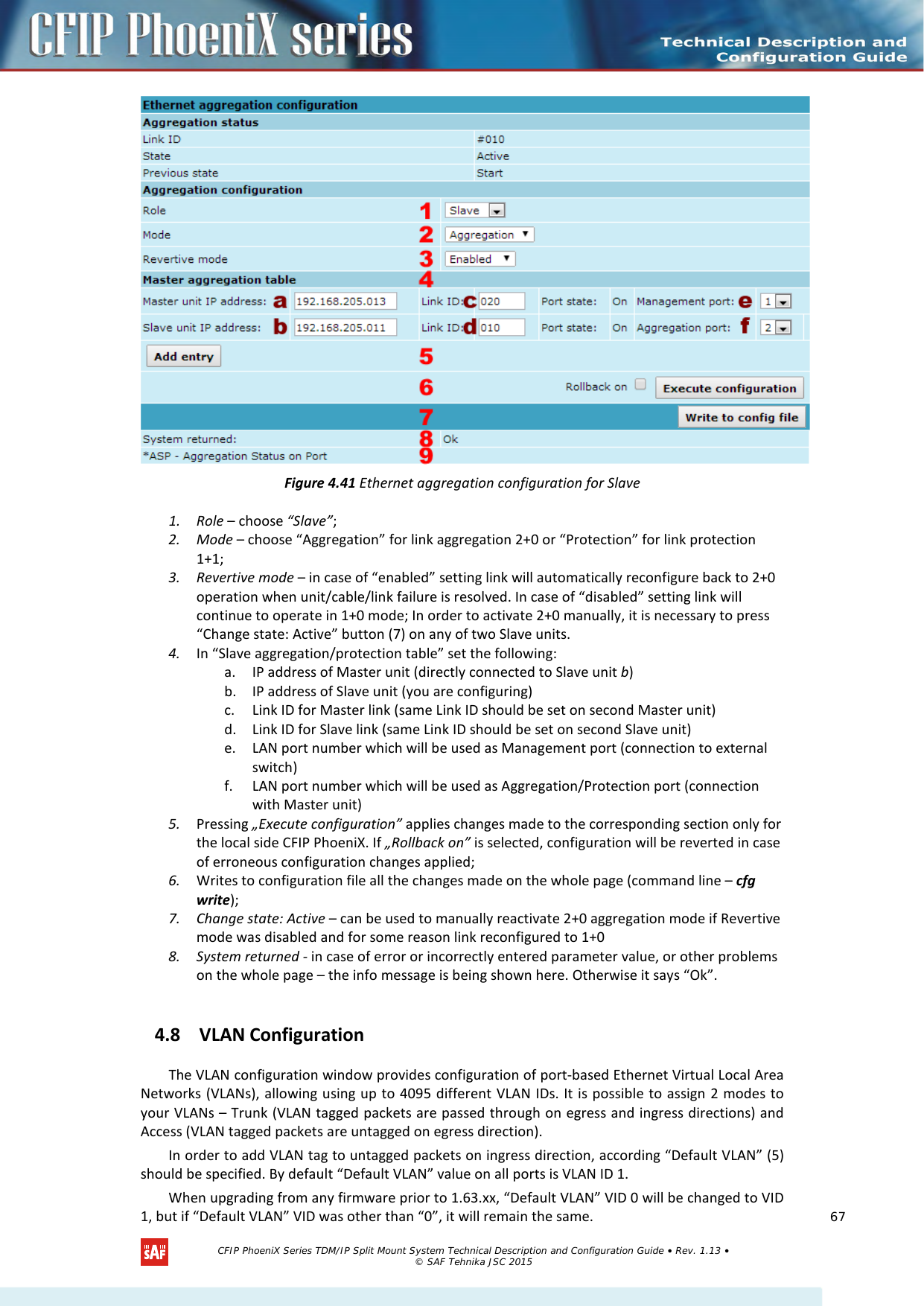
![Additionally starting from 1.63.xx firmware all ports (except WAN) by default are configured as Access VLAN ID 1. Figure 4.42 VLAN configuration 1. 802.1Q VLAN – enables support of 802.1Q VLAN (command line – ethernet vlan [enable | disable]); 2. 802.1Q Double Tagging – enables double tagging feature, which is useful for ISP applications. When the ISP aggregates incoming traffic from each individual customer, the extra tag (double tag) can provide an additional layer of tagging to the existing IEEE 802.1Q VLAN. The ISP tag (extra tag) is a way of separating individual customers from other customers. Using the IEEE 802.1Q VLAN tag, a user can separate the individual customer’s traffic. If P1-P4 (LAN1-LAN4) is being used in Access mode, it is required to enable this option (command line – ethernet vlan doubletag [enable | disable]); With enabled QinQ feature, client VLAN (C-tag) stays with default Ether type 0x8100 and Service tag (S-tag) is added with Ether type 0x9100. 3. VLAN Nr.\Port – displays all 6 ports of CFIP PhoeniX switch; 4. Default VLAN – specifies default VID for untagged frames; Must match VLAN ID if port is set to Access mode – example for Management port is seen on Figure 4.42 (command line – ethernet vlan <N> default <port list>); 5. VLAN table displays the list of set VLAN IDs and appropriate VLAN types on all available switch ports (command line – ethernet vlan status); 6. Select/Deselect all VLAN(-s) – Allows selecting or deselecting all VLANs of the corresponding column; 7. You can delete single VLANs or VLAN ranges by entering preferable VID range and pressing “Del” button; 8. By pressing “Execute configuration” changes made to the corresponding section apply only for the local side CFIP PhoeniX. If “Rollback on” is selected, configuration will be reverted in case erroneous configuration changes are applied. (!) When upgrading from any firmware prior to 1.63.xx you had VLAN configuration applied, management access will be available with previously specified management VLAN ID (as Default VLAN ID will remain the same), but it will be required to delete VLAN ID 1 from VLAN configuration table in order to make any further changes to VLAN configuration table. CFIP PhoeniX Series TDM/IP Split Mount System Technical Description and Configuration Guide • Rev. 1.13 • © SAF Tehnika JSC 2015 68](https://usermanual.wiki/SAF-Tehnika-AS/58F2DMX.User-Manual-1/User-Guide-3623550-Page-68.png)
![9. You can add VLANs by entering preferable VID, enabling appropriate port, choosing VLAN type and pressing “Add” button (command line – ethernet vlan <N[ - N]> {Delete} | {Port <port list [1[u]] [2[u]] [3[u]] [4[u]] [5[u]] [6[u]]>); 10. Reset VLAN(-s) – resets the whole VLAN configuration (command line – ethernet vlan reset); 11. Writes to configuration file all the changes made on the whole page (command line – cfg write); 12. System returned - in case of error or incorrectly entered parameter value, or other problems on the whole page – the info message is being shown here. Otherwise it says “Ok”. 4.8.1 Ethernet Switch Port Status and Settings Figure 4.43 Ethernet switch ports Switch LAN ports 1, 2, 3 and 4 are connected to LAN interface. Switch WAN port is connected to WAN interface, modem and radio part. Switch Mng port is connected to LAN Management CPU. 4.8.2 Ethernet Switch VLAN Status and Settings Figure 4.44 System without VLANs CFIP PhoeniX Series TDM/IP Split Mount System Technical Description and Configuration Guide • Rev. 1.13 • © SAF Tehnika JSC 2015 69](https://usermanual.wiki/SAF-Tehnika-AS/58F2DMX.User-Manual-1/User-Guide-3623550-Page-69.png)
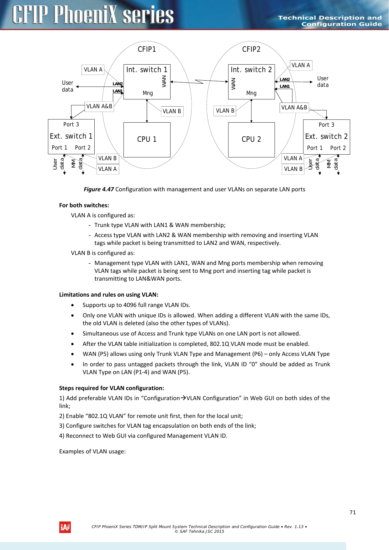
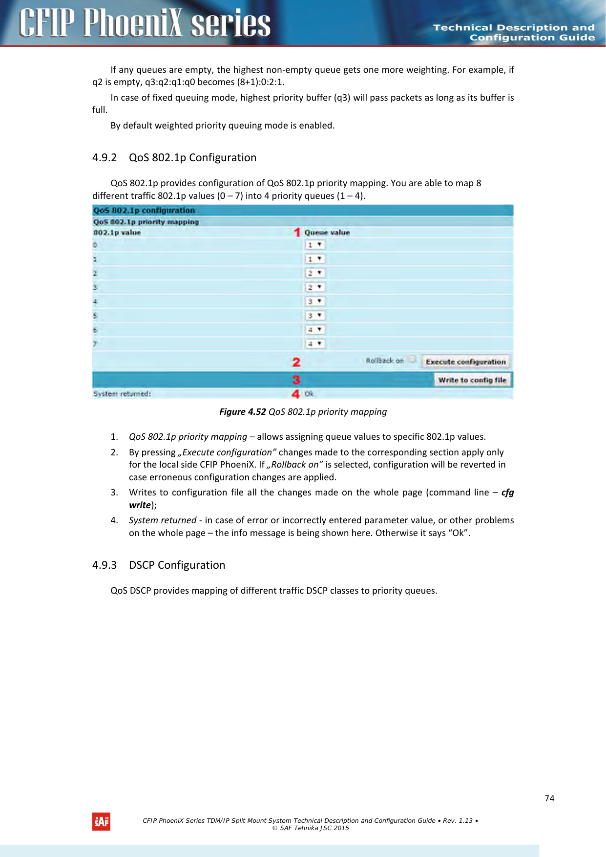
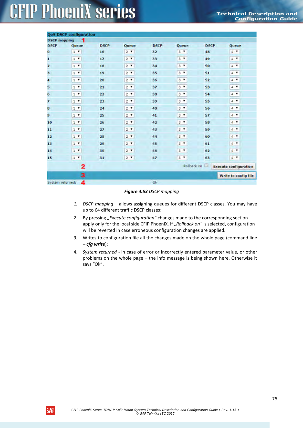
![Figure 4.48 VLAN configuration of CFIP PhoeniX link 4.9 QoS 4.9.1 General Configuration QoS status provides control over main QoS parameters, accordingly allowing enabling or disabling QoS 802.1p, DiffServ or port based priorities and change priority queuing mode. Figure 4.49 QoS general configuration 1. QoS 802.1p – enables or disables 802.1p priorities for any available switch port – LAN1/2/3/4, WAN or Mng (command line – ethernet QoS 802.1p {[enable | disable <Port>] | [map]}); CFIP PhoeniX Series TDM/IP Split Mount System Technical Description and Configuration Guide • Rev. 1.13 • © SAF Tehnika JSC 2015 72](https://usermanual.wiki/SAF-Tehnika-AS/58F2DMX.User-Manual-1/User-Guide-3623550-Page-72.png)
![2. DiffServ – enables or disables DiffServ (DSCP) priorities for any available switch port – LAN1/2/3/4, WAN or Mng (command line – ethernet QoS DSCP [enable | disable <port>] | map); 3. Port based priority – implies ingress packets on specified ports directly to priority queue set. By default port based priority queuing passes packets from all ports to lowest (1) priority queue (command line – ethernet QoS port <port> <priority>); 4. Queuing priority selection – allows to select primary QoS method, upon which queueing decision shall be made; 5. Queuing type – allows choosing fixed priority queuing mode or weighted queuing mode; 6. Weights (0<Q1<Q2<Q3<Q4<50) – allows specifying correlation of all four queues. Queue values should correspond to limitations. Default correlation is 1:2:4:8. 7. By pressing „Execute configuration” changes made to the corresponding section apply only for the local side CFIP PhoeniX. If „Rollback on” is selected, configuration will be reverted in case erroneous configuration changes are applied. 8. Writes to configuration file all the changes made on the whole page (command line – cfg write); 9. Execution status - in case of error or incorrectly entered parameter value, or other problems on the whole page – the info message is being shown here. Otherwise it says “Ok”. Figure 4.50 Weighted priority queuing mode Figure 4.51 Fixed priority queuing mode In case of weighted priority queuing mode, highest (q3) priority buffer may pass up to 8 consecutive packets subsequently proceeding to lower priority buffer (q2), which may pass up to 4 consecutive packets. This means that highest priority after passing 8 consecutive packets will wait no longer than until 7 packets of lower priorities pass (4(q2)+2(q1)+1(q0)). CFIP PhoeniX Series TDM/IP Split Mount System Technical Description and Configuration Guide • Rev. 1.13 • © SAF Tehnika JSC 2015 73](https://usermanual.wiki/SAF-Tehnika-AS/58F2DMX.User-Manual-1/User-Guide-3623550-Page-73.png)
![5 Performance and Alarm Management 5.1 Alarm Management 5.1.1 Alarms and Events Structure All alarms and events are placed in indexed table. Low level raw alarms and events are placed in the first table. Raw alarms and events are merged in groups, which are placed in the second indexed group table. Raw alarm table and group table are related one to many, or one to one if each alarm has a separate group (see Figure 5.1). Group is in SET state if one or more group members are in SET state. If there is no info about any group member alarm or event state, then there is no info about group state too. Figure 5.1 Alarm and group table relation 5.1.2 Alarms-Events and Groups Tables Most groups write log when group state changes (Set/Reset), but some groups are only rising. Alarms events and event groups: Alarm ID Group ID Alarm-Event name Description 1 1 ==> System Start Software started [Only rising] 2 2 Invalid device license License is not valid 3 3 License expired License validity has expired 4 4 License will soon expire License validity will soon expire 5 5 Log was Cleared Entered when ‘Log Clear’ command was called [Only rising] 6 6 Log ERROR Log data structure missing 7 7 Log TEST Log test was made 8 8 Counters was Cleared System performance counters were cleared [Only rising] 9 9 Config was Written Configuration was written [Only rising] 10 10 System CPU restart ==> Entered when system restart was called [Only rising] 11 11 No data from IDU temperature sensor No data from temperature sensor connected via I2C interface 1 alarm_list (indexed table) alarm_idx (index field) alarm_group (group id field) alarm_group_list (indexed table) alarm_goup (index field) ∞ Description fields ... Description fields ... CFIP PhoeniX Series TDM/IP Split Mount System Technical Description and Configuration Guide • Rev. 1.13 • © SAF Tehnika JSC 2015 81](https://usermanual.wiki/SAF-Tehnika-AS/58F2DMX.User-Manual-1/User-Guide-3623550-Page-81.png)
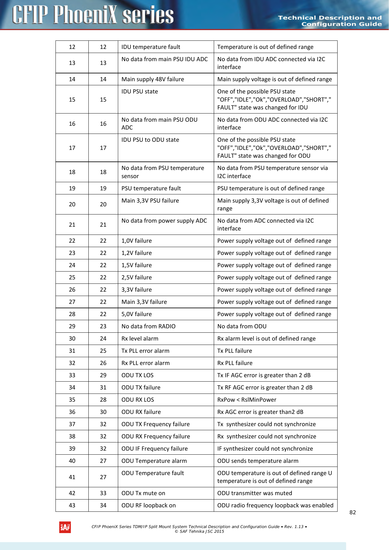
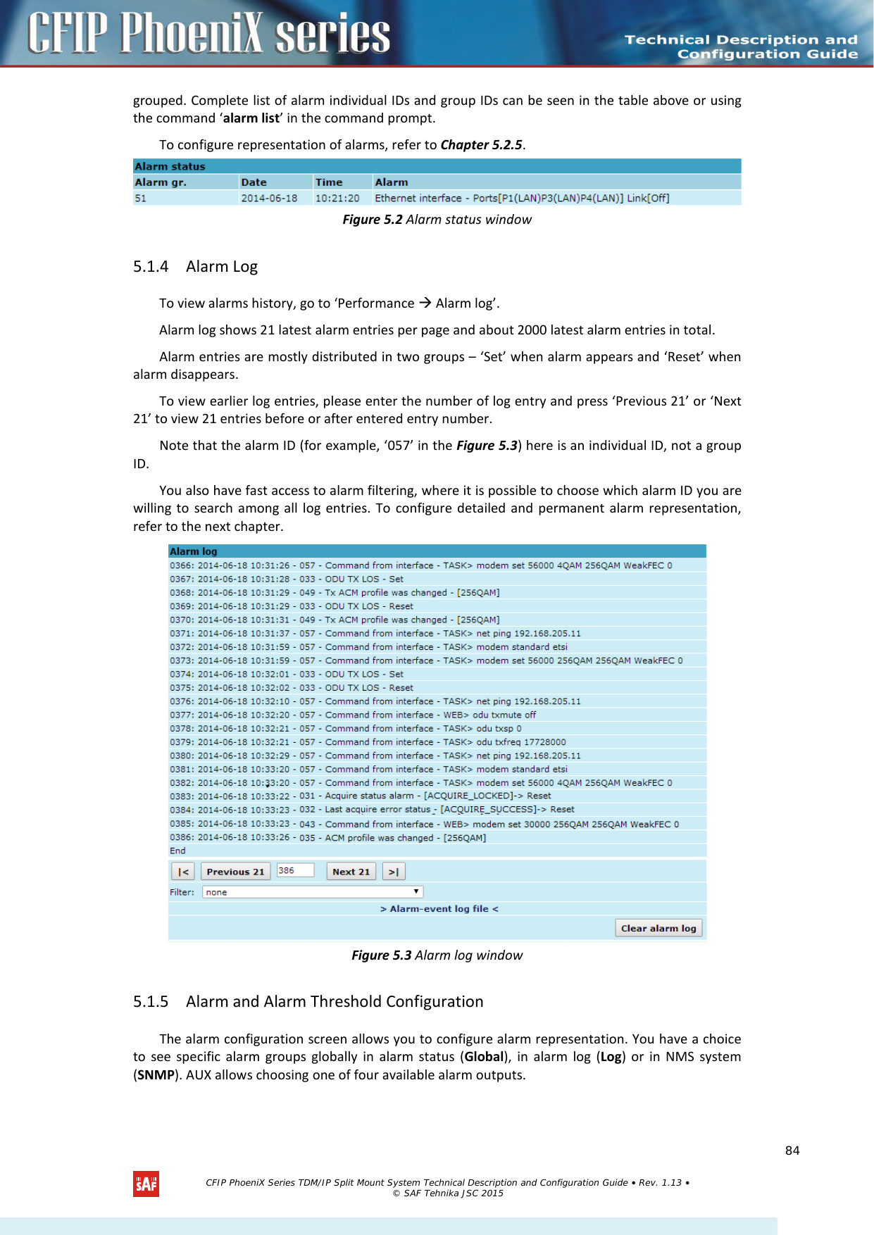
![44 35 No data from MODEM No data from MODEM connected via UART interface 45 36 Acquire status alarm Modem acquire failure status 46 37 Last acquire error status Modem last acquire failure status 47 38 Radial MSE Radial MSE is out of defined range 48 39 LDPC decoder stress LDPC decoder stress is out of defined range 49 40 Tx ACM profile was changed ACM profile was changed 50 41 RX carrier offset Error in Rx carrier offset 51 42 No data from modem temperature sensor No data from modem temperature sensor via I2C interface 52 43 Modem temperature fault Modem temperature is out of defined range 53 44 ATPC Tx power correction was changed ATPC Tx power correction was changed 54 45 Rollback initiate system CPU restart ==> System restart was called by rollback [Only rising] 55 46 System CPU reset was WDT initiated ==> System restart was called by watchdog [Only rising] 56 47 PM log flash write error Error while writing pm log to flash 57 48 Command from interface Message about command execution from particular interface 58 49 Message of event Informative message 59 50 E1/T1 interface E1/T1 interface state was changed 60 51 Eth interface No connection to Ethernet LAN port 61 52 AUX alarm in 1 AUX alarm 1 was enabled 62 53 AUX alarm in 2 AUX alarm 2 was enabled 63 54 AUX alarm in 3 AUX alarm 3 was enabled 64 55 AUX alarm in 4 AUX alarm 4 was enabled 65 56 No protection data from alternate If 1+1 protection is enabled and no data from alternate (paired) device 66 57 Protection state was changed Protection state was changed 67 58 Aggregation state was changed Event of aggregation state change in aggregation 2+0 configuration 68 59 Aggregation events Event of aggregation 2+0 configuration 69 60 Keepalive ethernet switch reset Ethernet switch does not respond and thus is reset 5.1.3 Alarm Status Window ‘Status Alarm status’ in navigation bar shows you all the current alarms. Date and time represents the time the alarm appeared, so you can easily evaluate for how long the alarm has been active. ‘Alarm gr.’ is the number of alarm group in which the specific alarm is CFIP PhoeniX Series TDM/IP Split Mount System Technical Description and Configuration Guide • Rev. 1.13 • © SAF Tehnika JSC 2015 83](https://usermanual.wiki/SAF-Tehnika-AS/58F2DMX.User-Manual-1/User-Guide-3623550-Page-83.png)
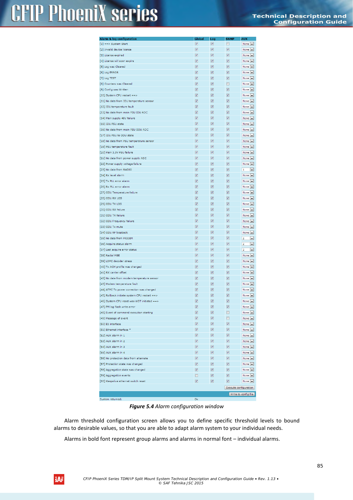
![Figure 5.5 Alarm threshold configuration window 5.1.6 Alarm Management Commands To manage alarms in command prompt, the commands are as follows: Alarm management commands Command Description Log show [<start line>] The management controller maintains event log, - events include configuration changes, management controller restarts, and local site alarm changes. The “log show” or “log” commands display the latest 20 log entries, the log entries are numbered, - entry with the largest number is the latest event. The “log show” command can be followed up with an entry number to display the latest 20 entries beginning from the entry specified by the number, e.g., “log show 100” will display entries 100…120. CFIP PhoeniX Series TDM/IP Split Mount System Technical Description and Configuration Guide • Rev. 1.13 • © SAF Tehnika JSC 2015 86](https://usermanual.wiki/SAF-Tehnika-AS/58F2DMX.User-Manual-1/User-Guide-3623550-Page-86.png)
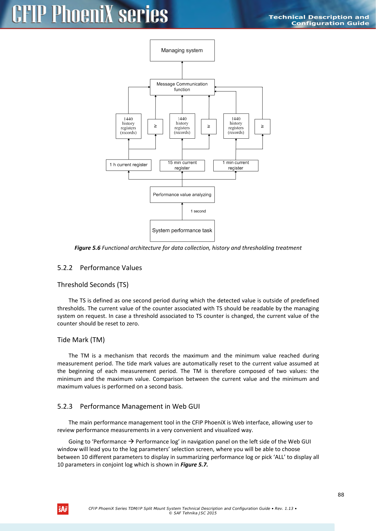
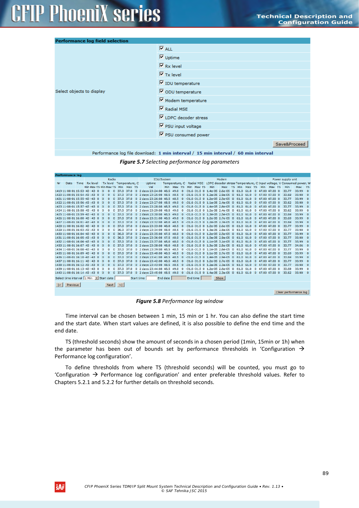
![5.2 Performance Management The main aim of the performance management is to register mostly critical device performance event values in predefined time intervals. 5.2.1 Performance Management Data Collection The performance parameters are collected within time intervals of 1 min., 15 min. and 1 hour. List reserved space for every time interval is 1440 records (see Figure 5.6). Second-by-second the input performance event values are stored by updating previous second values. The register is called current register. The current register contains the performance values collected second-by-second from the reset instant to the present second. At the end of period the contents of current registers are transferred to the history registers (records), with a time-date stamp to identify the period, after which the current register must be reset. Some current register values are passed to the threshold crossing control unit for triggering threshold crossing notification. Optionally, the same values are output to the Message Communication Function (MCF) to be forwarded to the managing system. Alarm management commands Command Description Log filter <alarm ID> [<num>] Filters event list by specific alarm ID. <start line> ; works similarly to ‘log show’ command. Log file <file name> Makes event log file with specified filename. Alarm stat Lists alarm groups currently set. Alarm list Displays the list of all alarms, their group IDs and alarm IDs. Alarm groups Displays the list of all alarms and their group IDs. Alarm cfg <group ID> [<global> <led> <aux> <log> <snmp>] Allows defining detailed alarm representation settings. [<global> <led> <aux> <log> <snmp>] must be defined in a row of ‘1’s or ‘0’s of 5 values for specified group ID with <group ID>. ‘1’ means the values are ‘on’ and ‘0’ – ‘off’. Alarm threshold {stat} | {<Alarm ID> lo|hi|delta <value>} Sets threshold values outside which alarm status will be shown. CFIP PhoeniX Series TDM/IP Split Mount System Technical Description and Configuration Guide • Rev. 1.13 • © SAF Tehnika JSC 2015 87](https://usermanual.wiki/SAF-Tehnika-AS/58F2DMX.User-Manual-1/User-Guide-3623550-Page-87.png)
![tfs edit <file> Edits the specified file. This command is applied for editing configuration backup files and boot configuration file (boot.ini). For example, edit boot.ini,Be – file ‘boot.ini’ will be opened for editing. ‘Be’ specifies that this file will be saved with attributes ‘B’ and ‘e’. If boot.ini file is intended to be modified, it should always be opened specifying ‘B’ and ‘e’ flags as in the example above, this will ensure that file is saved with these attributes (flags). To close the file and save changes press Ctrl+Z, to close the file without saving changes press Ctrl+Q. The configuration backup files do not require specific attributes. tfs ls Displays the list of files stored on the Flash disk and the number of bytes, both free and used by these files. ‘tfs dir’ can also be used. tfs cat <filename> Displays the contents of the text file. ‘tfs type’ can also be used. tfs del <filename> Deletes the specified file from Flash disk. ‘tfs rm’ can also be used. 6.5 Security commands General tips Telnet server supports one user only, web server supports up to 32 users simultaneously. By default the username and password for Web server, FTP server and Telnet terminal is: – Username (login): admin – Password: changeme The username and password can be changed in Web GUI “System configuration User configuration” ‘access set <username> <password> [plaintext]’ command. Take note of upper case and lower case type: it should be taken into account for the password! The passwords may contain spaces; if using space(s), the password should be entered in quotation marks. For Telnet, FTP and Web GUI the password can be changed by simply entering the security command ‘access set <guest | admin> <password> [plaintext]’ while logged on and then saving the configuration in EEPROM by using ‘write’ command. To terminate Telnet session press Ctrl+D. (!) “guest” account is unable to change its access password. (!) Specification of the password should always be followed by saving the configuration script (using “cfg write” command); otherwise, the password request will be ignored after the restart of CFIP. CFIP PhoeniX Series TDM/IP Split Mount System Technical Description and Configuration Guide • Rev. 1.13 • © SAF Tehnika JSC 2015 106](https://usermanual.wiki/SAF-Tehnika-AS/58F2DMX.User-Manual-1/User-Guide-3623550-Page-106.png)