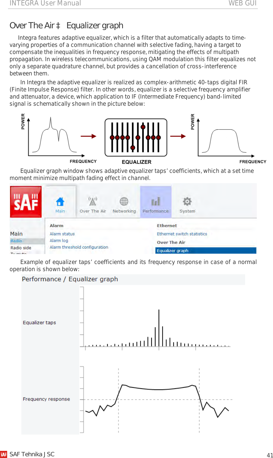
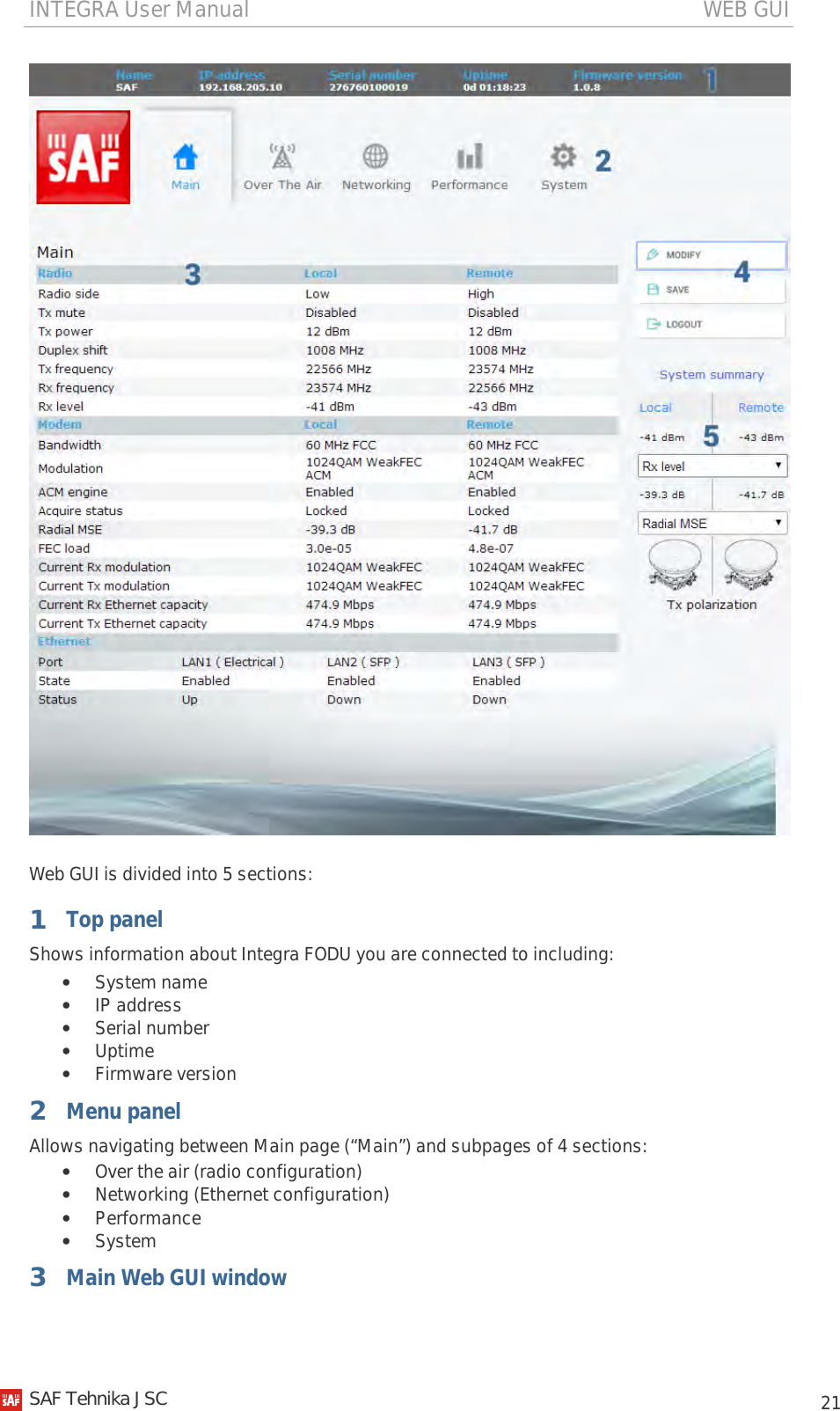
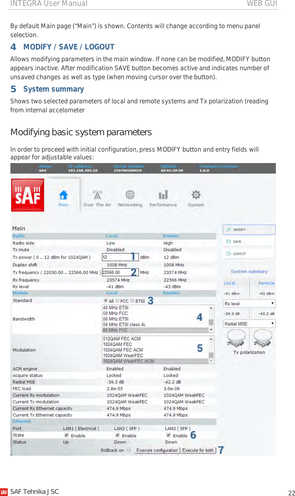
SAF Tehnika AS INTEGRA24 Low Power Point-To-Point Transmitter User Manual
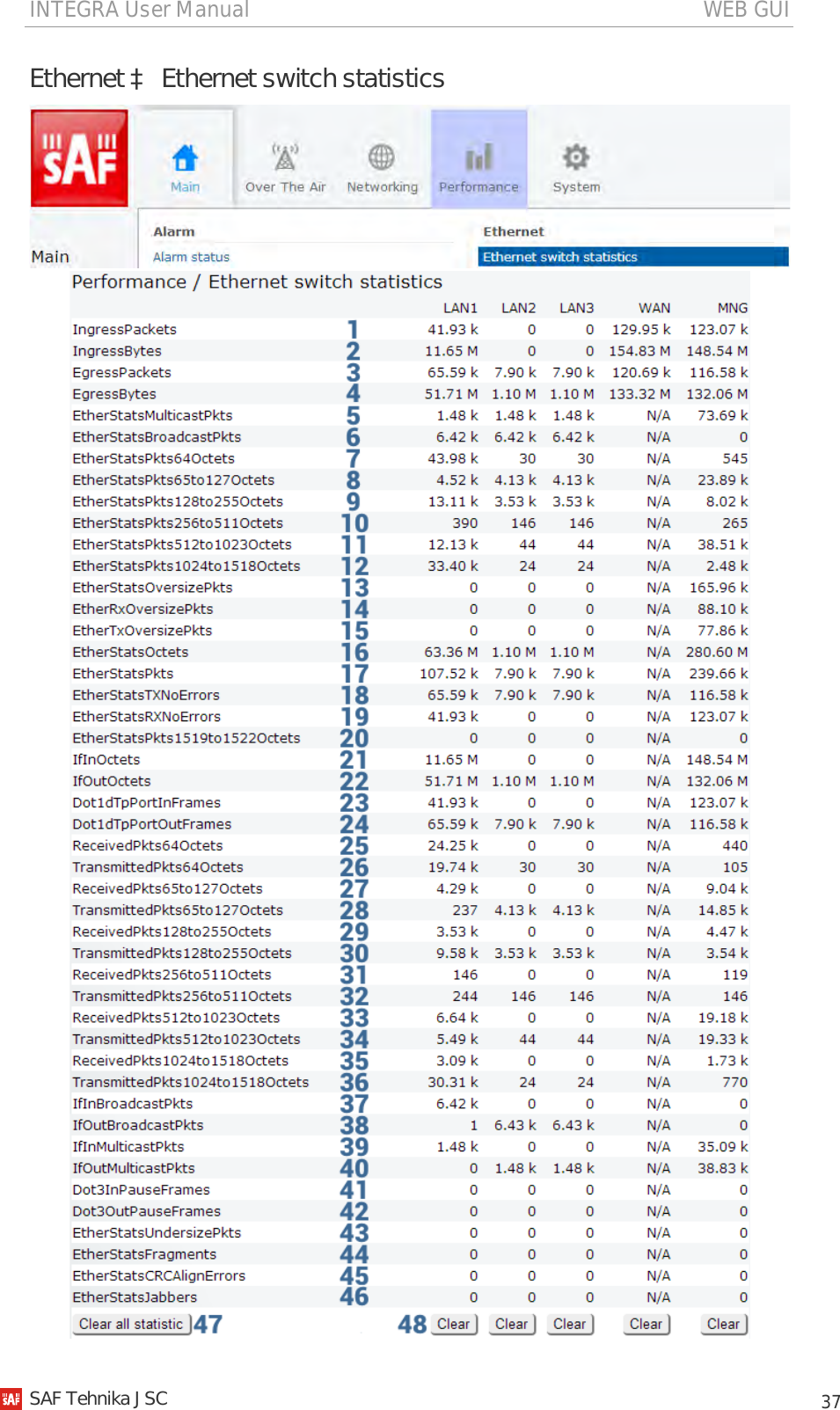
SAF Tehnika A/S Low Power Point-To-Point Transmitter
UserManual.wiki
>
SAF Tehnika AS
>
INTEGRA24 User Manual
User Manual
Navigation menu
Upload a User Manual
Namespaces
Wiki Guide
HTML
PDF
Info
Views
User Manual
Discussion / Help
Navigation

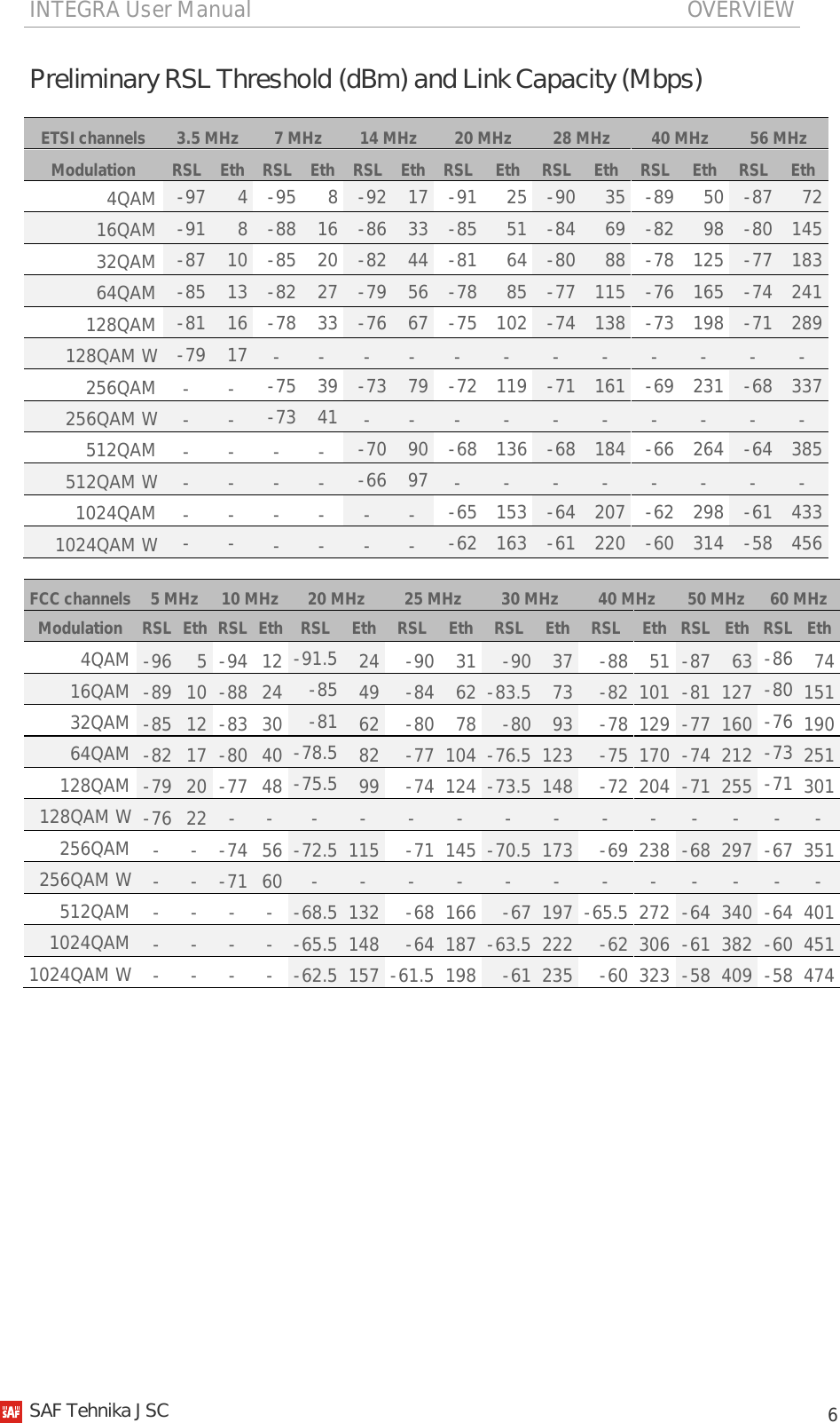

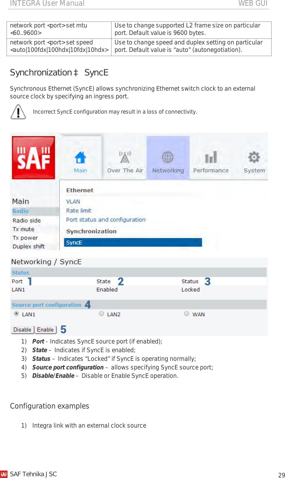
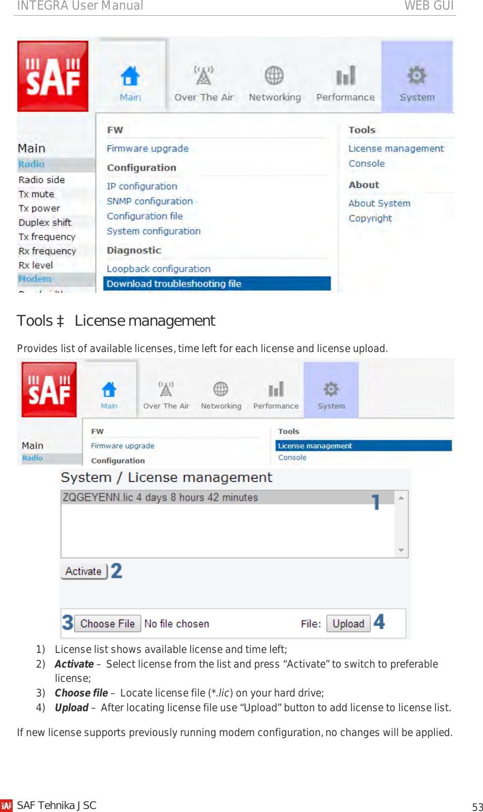
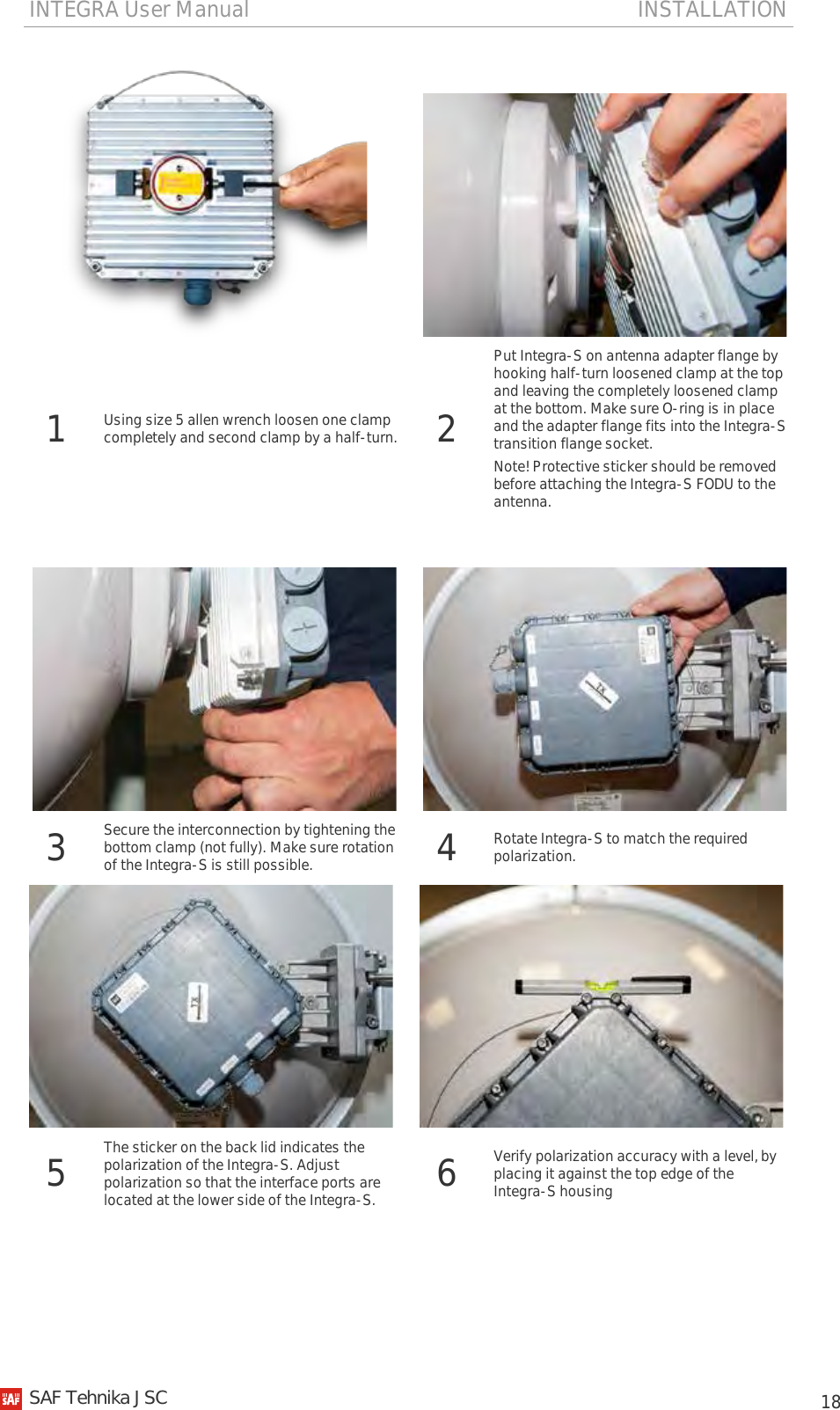
![INTEGRA User Manual INSTALLATION 12 Chapter 2: INSTALLATION Integra FODU: assembling mounting bracket and installing with antenna on a pole Disassembled mounting bracket and tools required for assembly Parts of disassembled mounting bracket: 1 – three (3) M8x1.25x16 hex flange bolts already attached to clamps for housing and pipe [7]; 2 – one (1) hex flange bolt M8x1.25x20; 3 – one (1) hex flange bolt M8x1.25x30, one (1) M10x1.5 hex flange nut and one (1) M8x80 eye screw already attached to clamps for housing and pipe [7]; 4 – one (1) M8x80 eye screw; 5 – two (2) M8x1.25 hex flange nuts already attached to M8x80 eye screw [3]; 6 – four (4) M8x160 threaded rods; 7 – clamps for housing and pipe interconnected with three (3) M8x1.25x16 hex flange bolts [1] and eye screw for horizontal alignment [3]; 8 – ten (10) M8x1.25 hex flange nuts; 9 – two (2) mounting bracket clamps. Parts of disassembled mounting bracket Parts of Integra FODU: 10 – spacer hex flange nut; 11 – lifting eye nut; 12 – fixation plate; 13 – side screw flange nuts; 14 – grounding flange nut. Numbers of mounting bracket and Integra FODU parts in next sections will be mentioned in square brackets []. 2 4 6 8 3 9 5 7 1 11 13 10 12 14 SAF Tehnika JSC](https://usermanual.wiki/SAF-Tehnika-AS/INTEGRA24/User-Guide-2412298-Page-12.png)
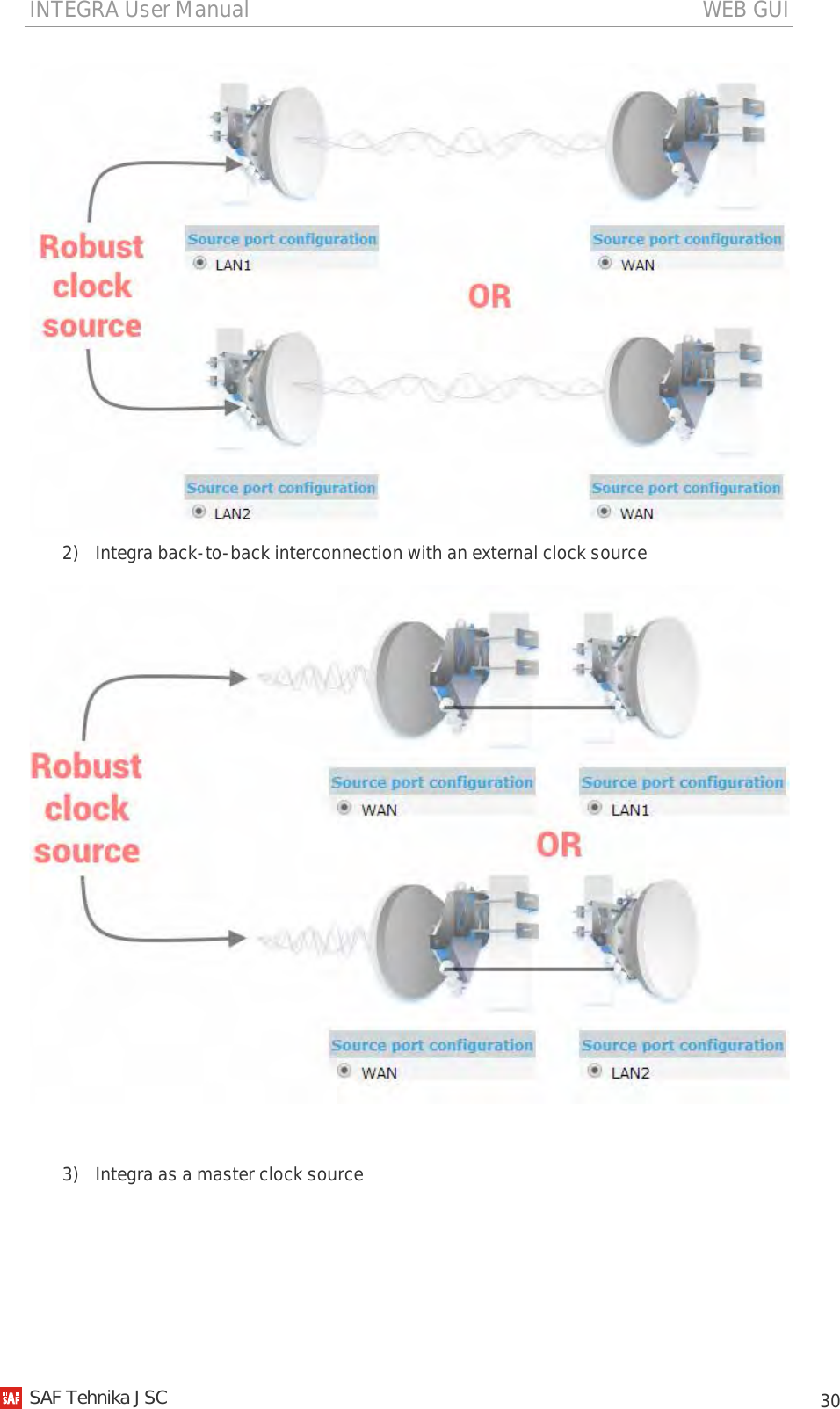
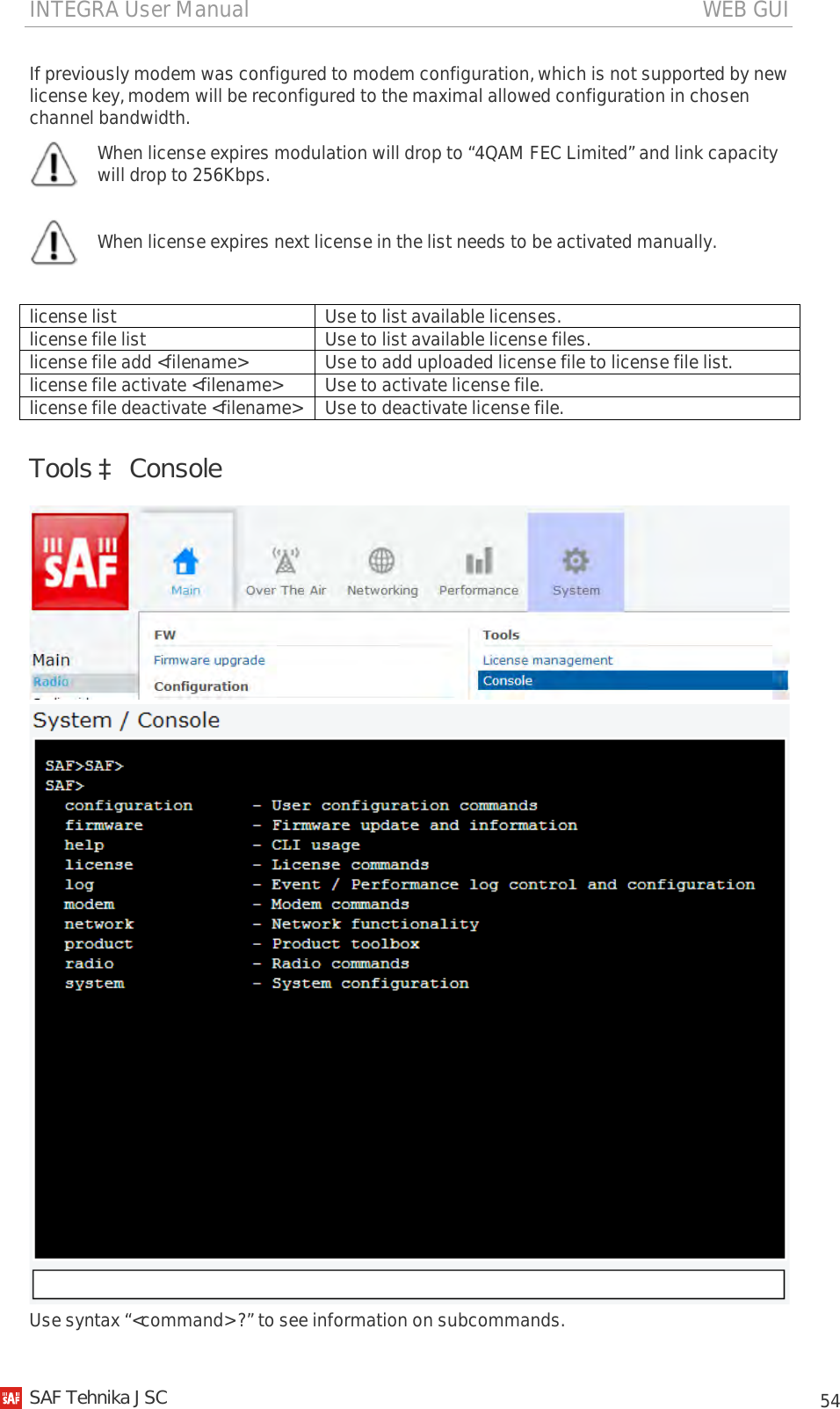
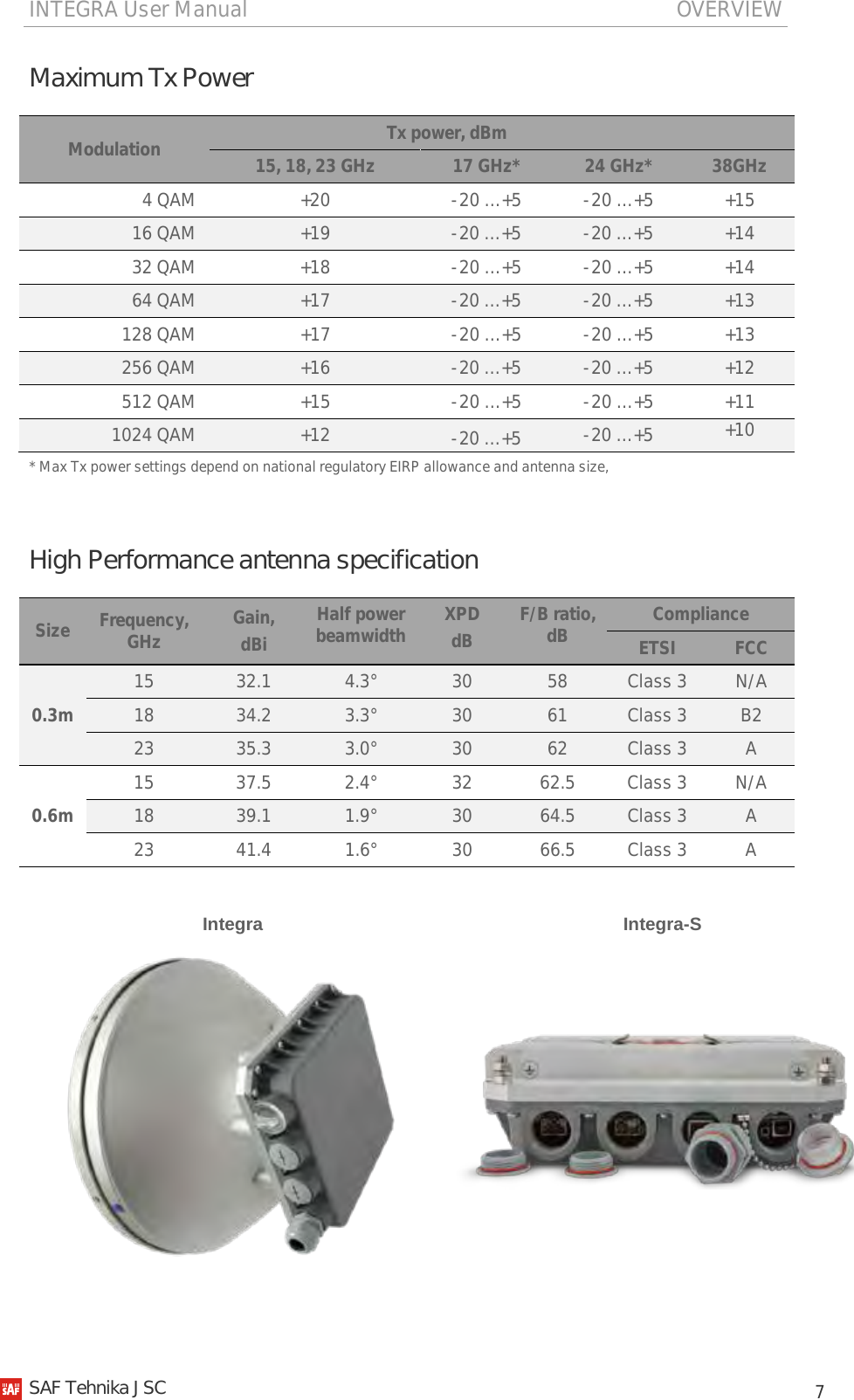
![INTEGRA User Manual INSTALLATION 13 Changing polarization of Integra FODU and antenna Tools required: 13mm (0.512”) wrench (comes in package) 1 Remove Integra FODU with antenna from mounting bracket. Default polarization is vertical. 2 Using 13mm wrench remove indicated nuts and fixation plate [10, 11, 12, 13, 14]. 3 Removed parts must be attached back with 90 degree offset (see above). Gap between side screw flange nuts [13] and fastening angles should be 5mm. 4 View of Integra FODU with swapped polarization. 5 30 cm antenna: when polarization is changed, make sure that drain hole cap located at grounding flange nut should be removed and inserted in previous drain hole. 6 60 cm antenna: make sure that one of two water drain holes is aligned with Integra FODU’s grounding flange nut. SAF Tehnika JSC](https://usermanual.wiki/SAF-Tehnika-AS/INTEGRA24/User-Guide-2412298-Page-13.png)
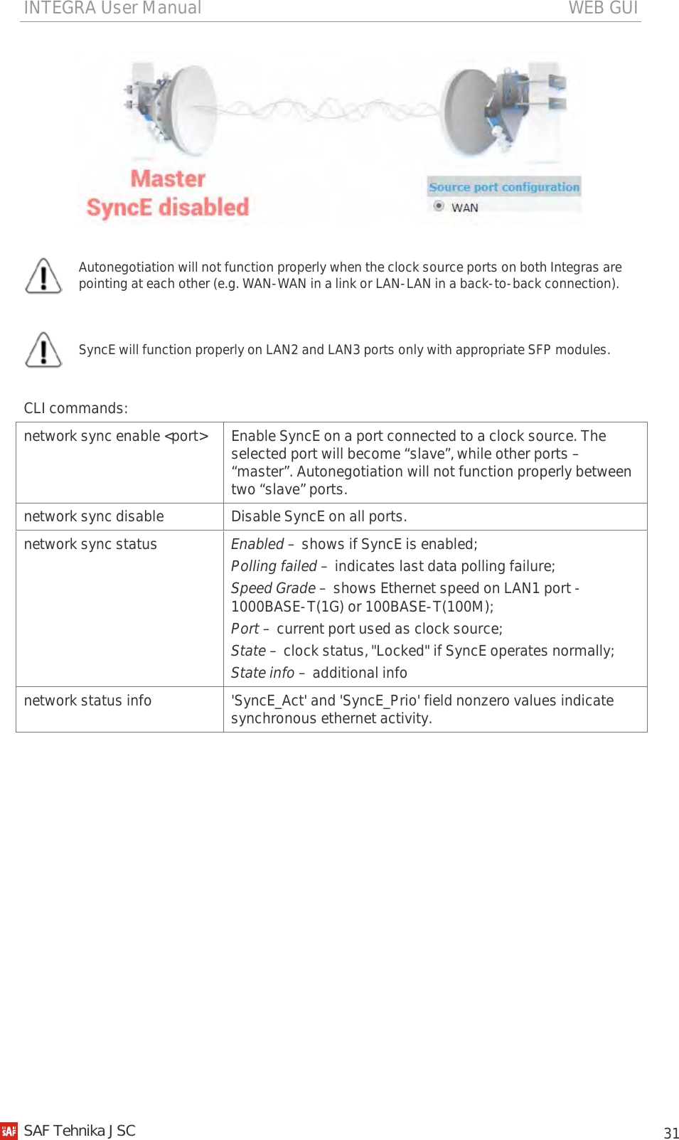
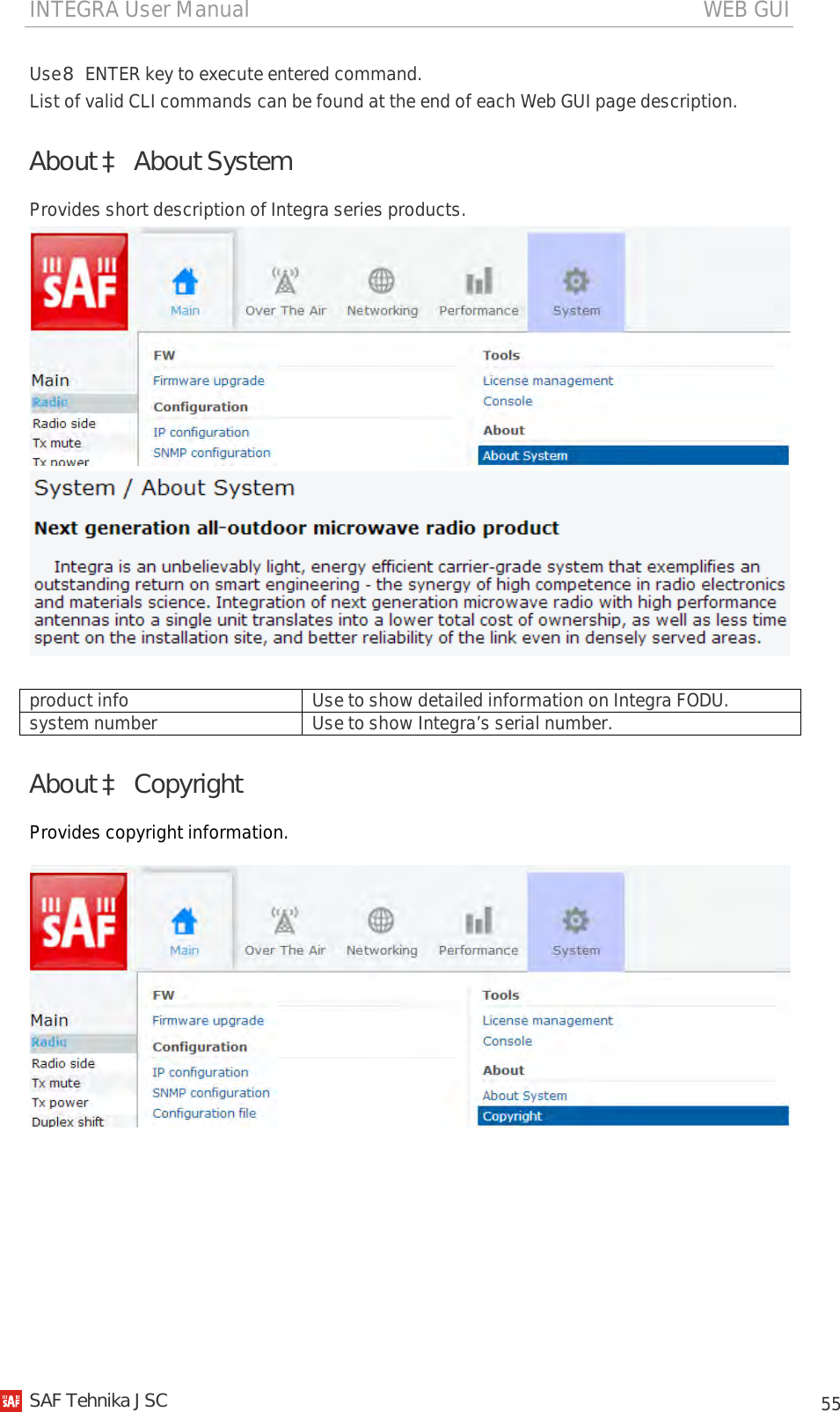
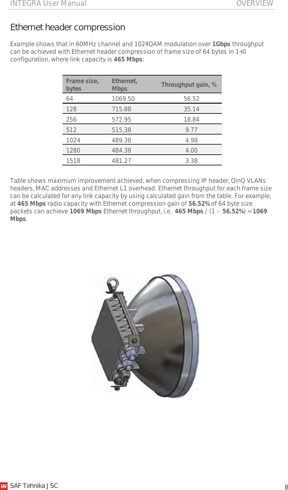
![INTEGRA User Manual INSTALLATION 14 Assembly procedure Tools required: 13mm (0.512”) wrench (comes in package) 1 Using 13mm wrench slightly loosen three hex flange bolts [1] and hex flange bolt, nut and eye screw [3] interconnecting clamps for housing and pipe [7]. 2 Attach vertical alignment eye screw [4] to clamps for housing and pipe [7] using hex flange bolt [2] and screw on two hex flange nuts [8]. Make sure that both eye screws are positioned as shown in the image (turned to the back side of clamps) and the gap between each two flange nuts on eye screws should be 15..20mm (0.6..0.8 in.). Do not tighten both hex flange bolts [3] and [2]. 3 Screw on one hex flange nut [9] on each of threaded rods [8]. Note that flange nuts should be screwed on exposing approx. 15mm (0.6 in.) of threaded rods. 4 Screw on each threaded bolt into four available threaded holes of mounting clamp. Note that threaded bolt should be visible from other side of the clamp not more than 2mm. Tighten hex flange nuts [9] with torsion 20..25 N·m. SAF Tehnika JSC](https://usermanual.wiki/SAF-Tehnika-AS/INTEGRA24/User-Guide-2412298-Page-14.png)
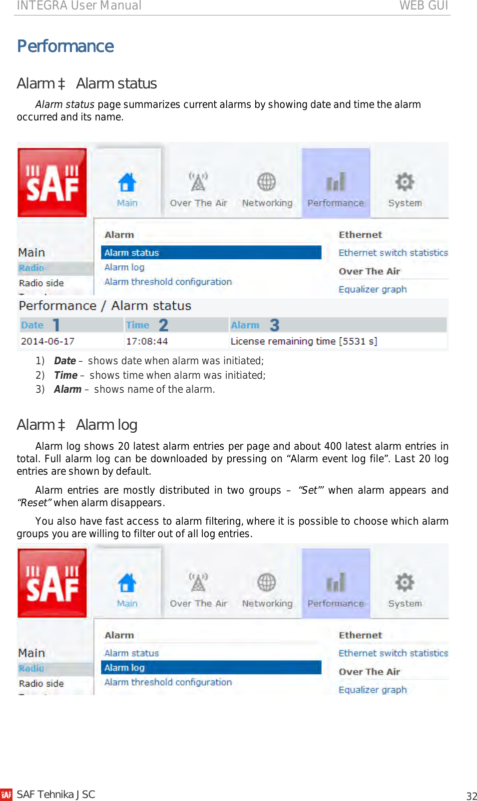
![INTEGRA User Manual INSTALLATION 15 5 Attach mounting bracket clamps [2] on two threaded rods [8] as shown on the picture and afterwards screw on remaining hex flange nuts [9] on each of four threaded rods. No parts should remain left not assembled. Bracket clamps in following position support mast ∅ 55..120mm. Reversing clamps allows support of smaller masts ∅ 25..75mm. 6 Unscrew hex flange nuts [9] from both free threaded bolts [8]. Make sure that hex flange nuts on opposite threaded bolts are not too far; otherwise adjust bolts’ position accordingly. Put other end of mounting bracket clamp [2] on free threaded bolt. 7 Hex flange nuts should be evenly aligned on threaded bolts so that both mounting bracket clamps [9] are tightly attached to the pipe. Tighten hex flange nuts with torsion not exceeding 20 N·m. 8 View of assembled mounting bracket on the mast pole. 9 Make sure that both horizontal and vertical alignment eye screws are turned to the mast before attaching Integra FODU. 10 Attach Integra FODU with antenna to the mounting bracket so that side screws fit into grooves of the housing clamp [7]. 11 Connect vertical alignment eye screw [4] to the upper groove on Integra housing. 12 View of assembled bracket on the mast pole with Integra FODU attached and secured. SAF Tehnika JSC](https://usermanual.wiki/SAF-Tehnika-AS/INTEGRA24/User-Guide-2412298-Page-15.png)
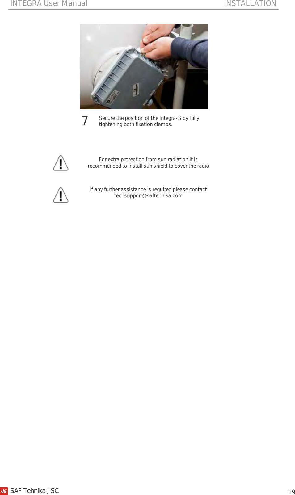
![INTEGRA User Manual INSTALLATION 16 For extra protection from sun radiation it is recommended to install sun shield to cover the radio Antenna alignment Tools required: 13mm (0.512”) wrench (comes in package) 1 Before aligning the antenna, make sure that screws marked with red dots on the right side view of mounting bracket are loosened - hex flange nuts and bolts of azimuth and elevation eye screws, right side screw on Integra FODU and hex flange bolt on azimuth angle indicator. 2 Additionally loosen following screws marked with red dots on the left side view of mounting bracket: left side screw on Integra FODU and two hex flange bolts between both mounting bracket clamps for housing and pipe. 3 For initial alignment make sure that elevation is approximately at zero degree angle by adjusting hex flange nuts [9] on vertical alignment eye screw so that Integra’s housing is parallel with the bracket. 4 Adjust azimuth angle by manually moving mounting bracket in horizontal axis. Note that all azimuth position fixing hex flange bolts [8], as well as horizontal alignment eye screw with flange bolt [3] need to be loosened ensuring free movement in horizontal axis. SAF Tehnika JSC](https://usermanual.wiki/SAF-Tehnika-AS/INTEGRA24/User-Guide-2412298-Page-16.png)
![INTEGRA User Manual INSTALLATION 17 5 Each notch corresponds to one degree of azimuth angle. Half distance between notches (each lip) corresponds to 0.5 degree. 6 Fix azimuth angle on horizontal axis by adjusting position of flange nuts [9] on both horizontal and vertical alignment eye screws. 7 When alignment is finished tighten screws marked with red dots on the right side view of mounting bracket: hex flange nuts and bolts of azimuth and elevation eye screws, right side screw on Integra FODU and hex flange bolt on azimuth angle indicator with torsion 20..25 N·m. 8 Additionally tighten following screws marked with red dots on the left side view of mounting bracket: left side screw on Integra FODU and two hex flange bolts between both mounting bracket clamps for housing and pipe with torsion 20..25 N·m. Integra-S FODU: attaching to the antenna Parts of Integra-S FODU: 1 – O-ring; 2 – flange protecting sticker; 3 – wire handle; 4 – fixation clamps; 5 – grounding screws. Tools required: Size 5 allen wrench Level (not supplied) 3 4 1 2 5 SAF Tehnika JSC](https://usermanual.wiki/SAF-Tehnika-AS/INTEGRA24/User-Guide-2412298-Page-17.png)
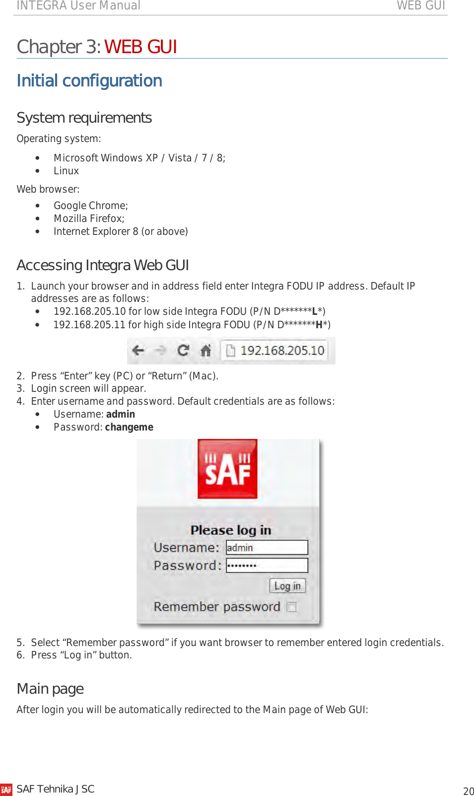
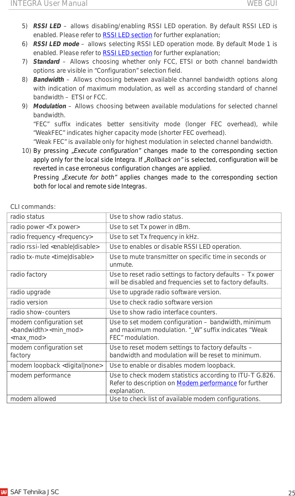
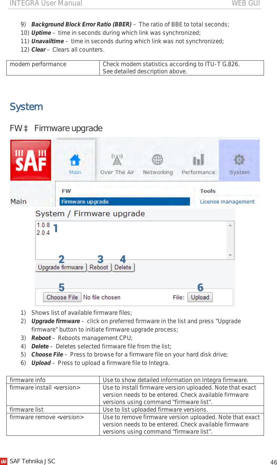
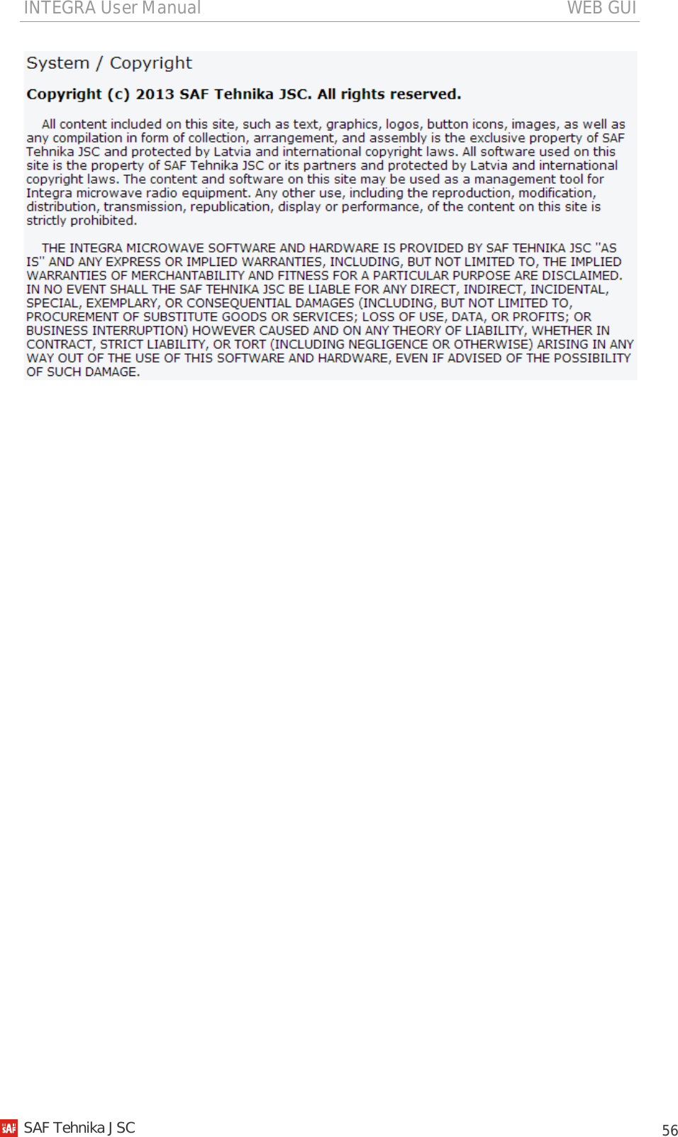
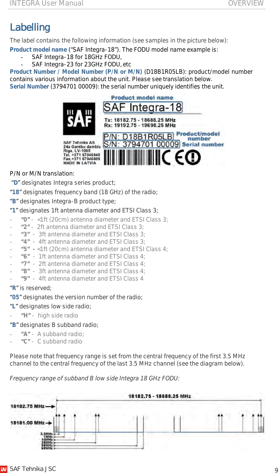
![INTEGRA User Manual WEB GUI 24 Over The Air Radio à Configuration Radio configuration page is available in “System” menu (Over The AiràRadioàConfiguration). 1) Tx power – Available range depends on radio model and selected modulation. Actual range will be indicated in the brackets; 2) Tx frequency – Available range depends on frequency band, subband, radio side and channel bandwidth selected. Actual range will be indicated in the brackets. Tx frequency range indicates range of central frequencies for configured channel bandwidth. Default frequency range (indicated on the label) is defined for 3.5MHz channel bandwidth. 3) Tx mute [ >=10 sec ] – allows muting transmitter to limited time interval in seconds. Minimum value is 10 seconds. Note that transmitter will be muted only if valid value in seconds is entered; 4) RSSI Audio – allows disabling/enabling RSSI audio operation on 3.5mm jack beside USB port. By default RSSI Audio is enabled; SAF Tehnika JSC](https://usermanual.wiki/SAF-Tehnika-AS/INTEGRA24/User-Guide-2412298-Page-24.png)