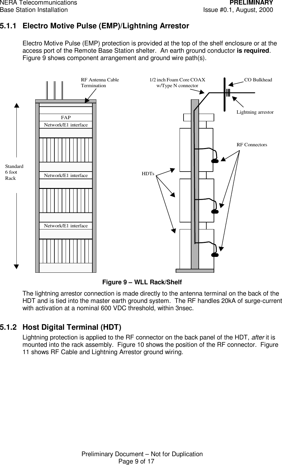
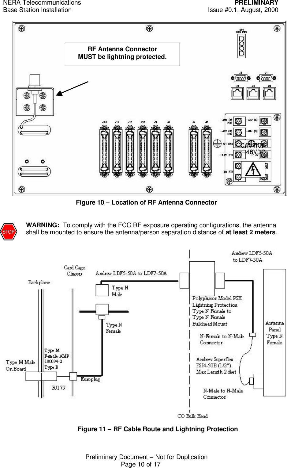
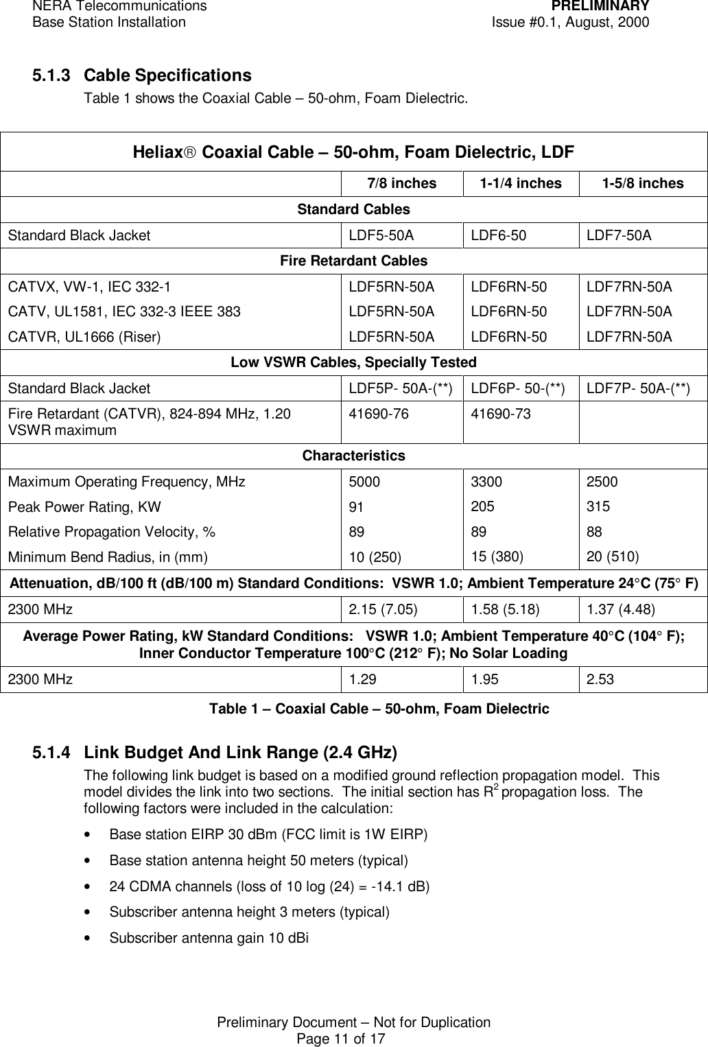
SRT Acquisition BSHDT Base Station Transeiver User Manual Base Station Installation
SRT Acquisition Base Station Transeiver Base Station Installation
UserManual.wiki
>
SRT Acquisition
>
BSHDT User Manual
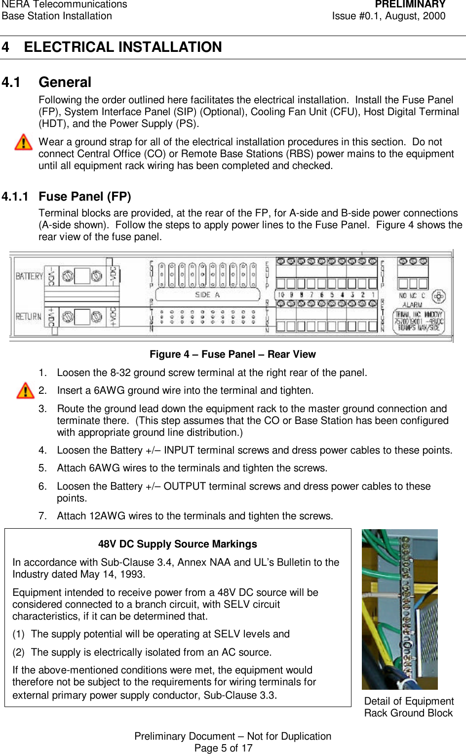
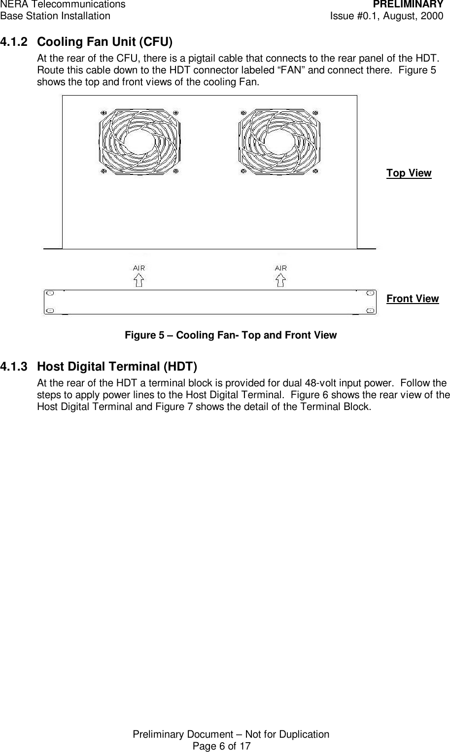
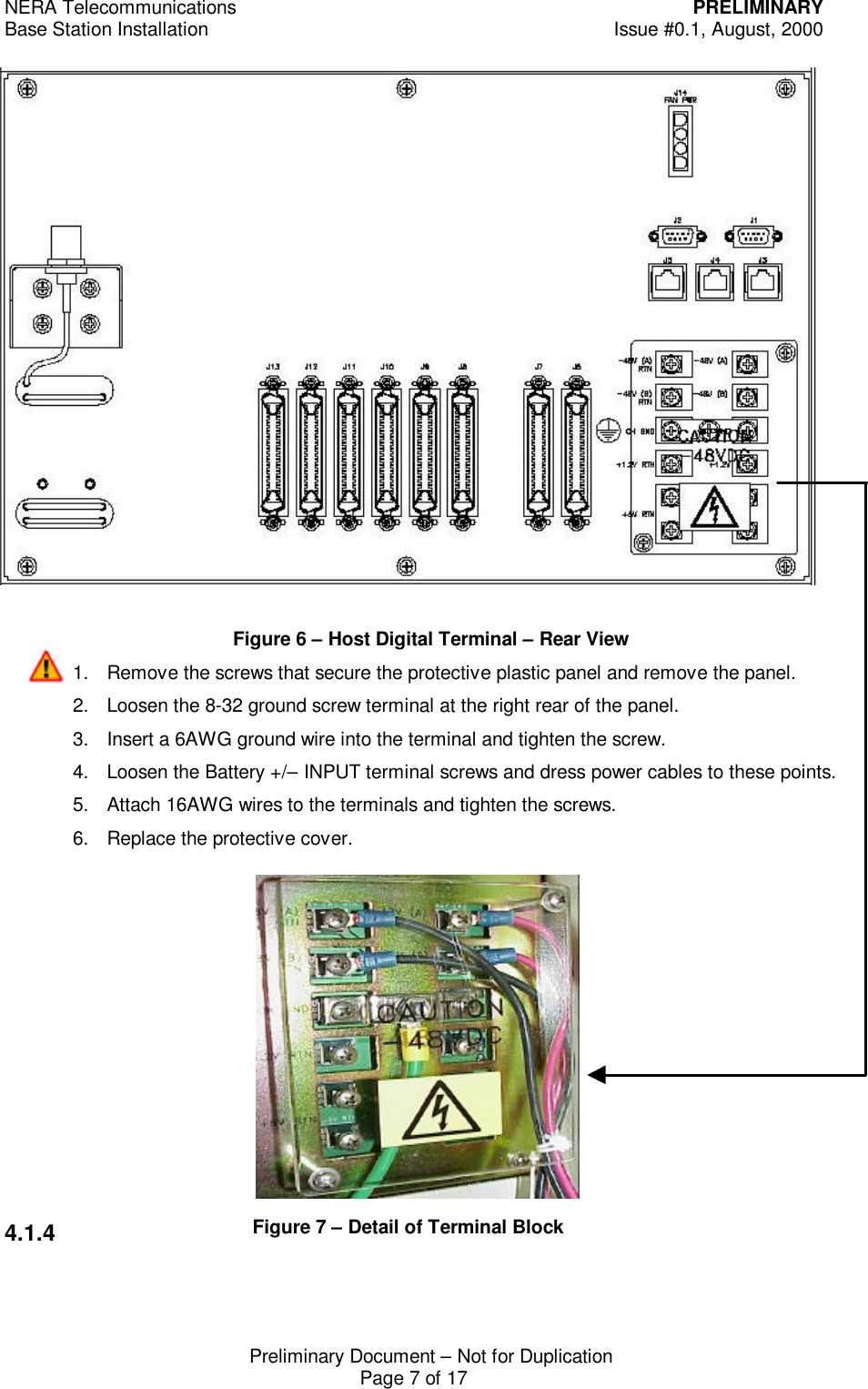
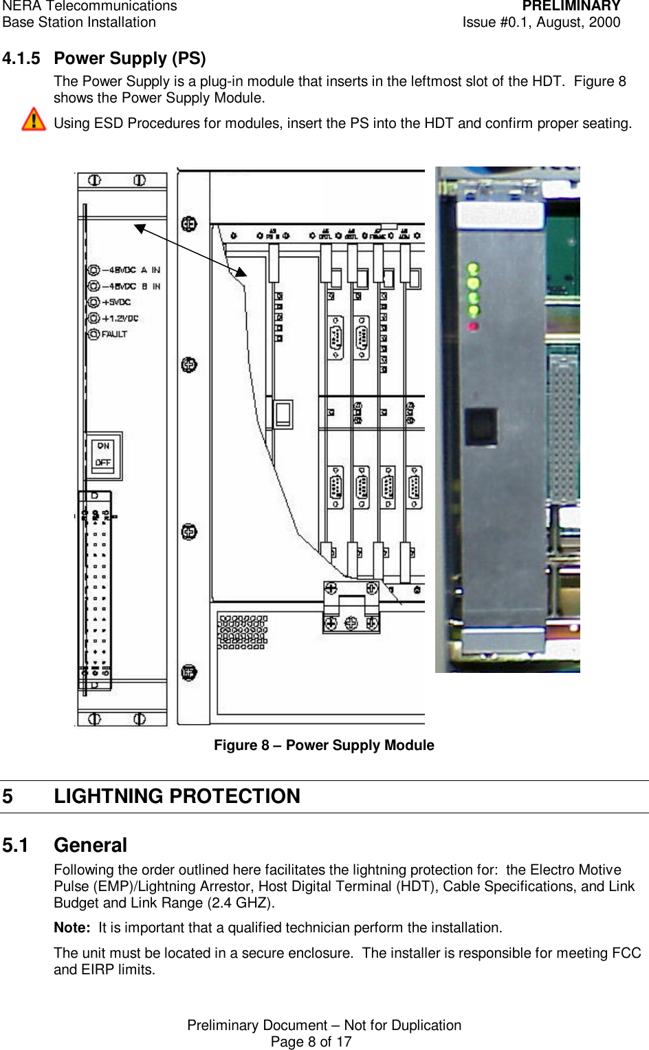
Installation manual
Navigation menu
Upload a User Manual
Namespaces
Wiki Guide
HTML
PDF
Info
Views
User Manual
Discussion / Help
Navigation