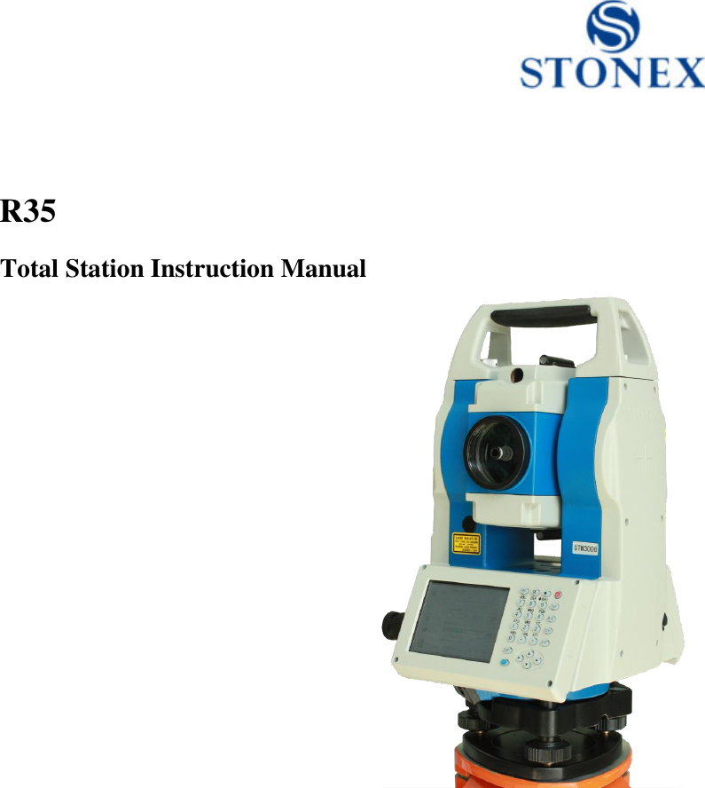
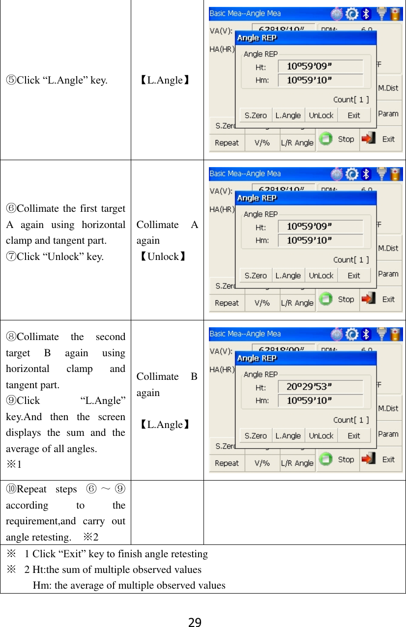
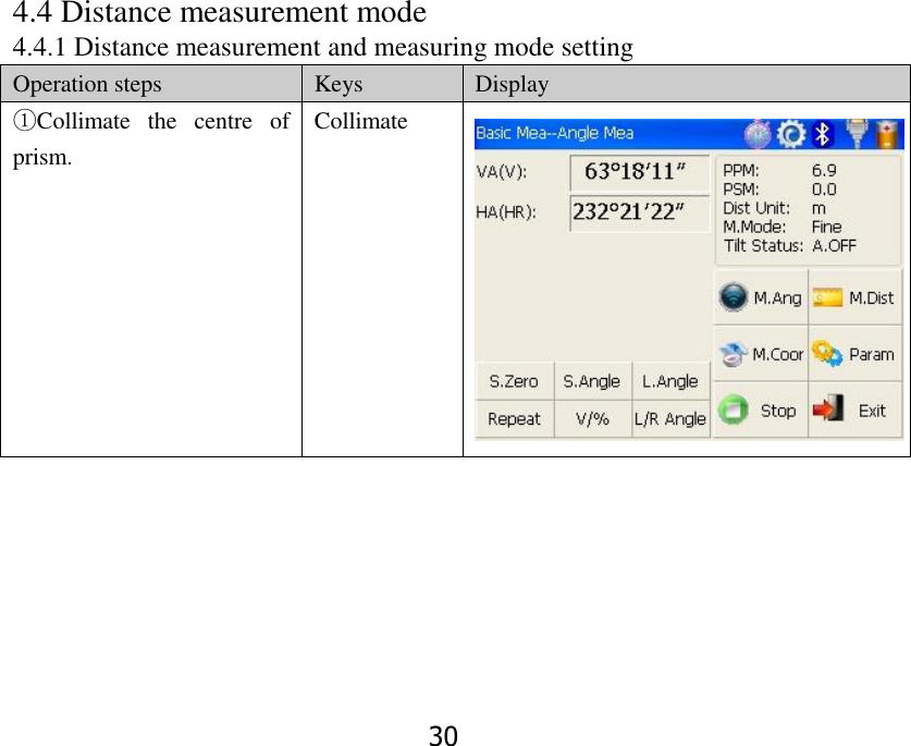
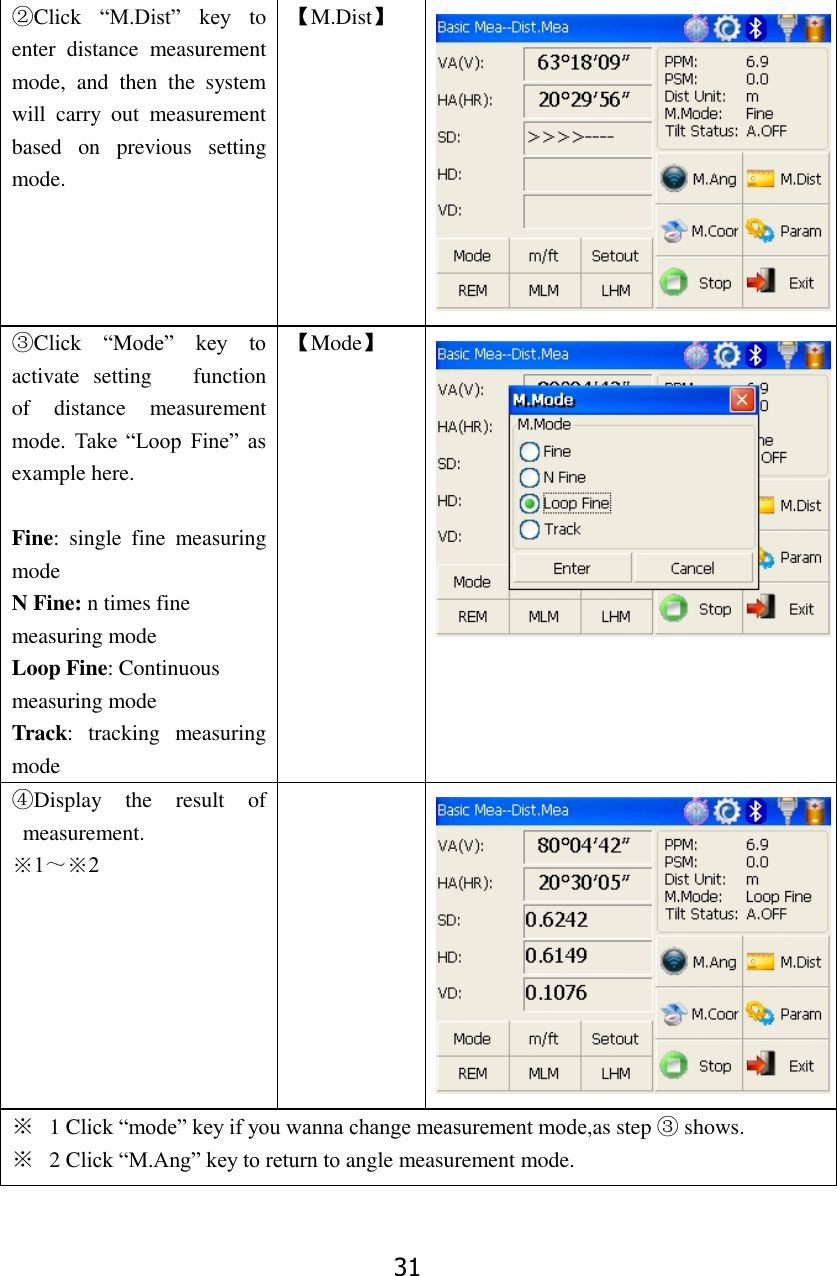
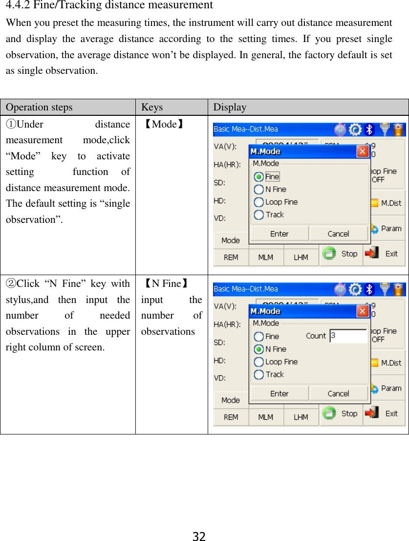
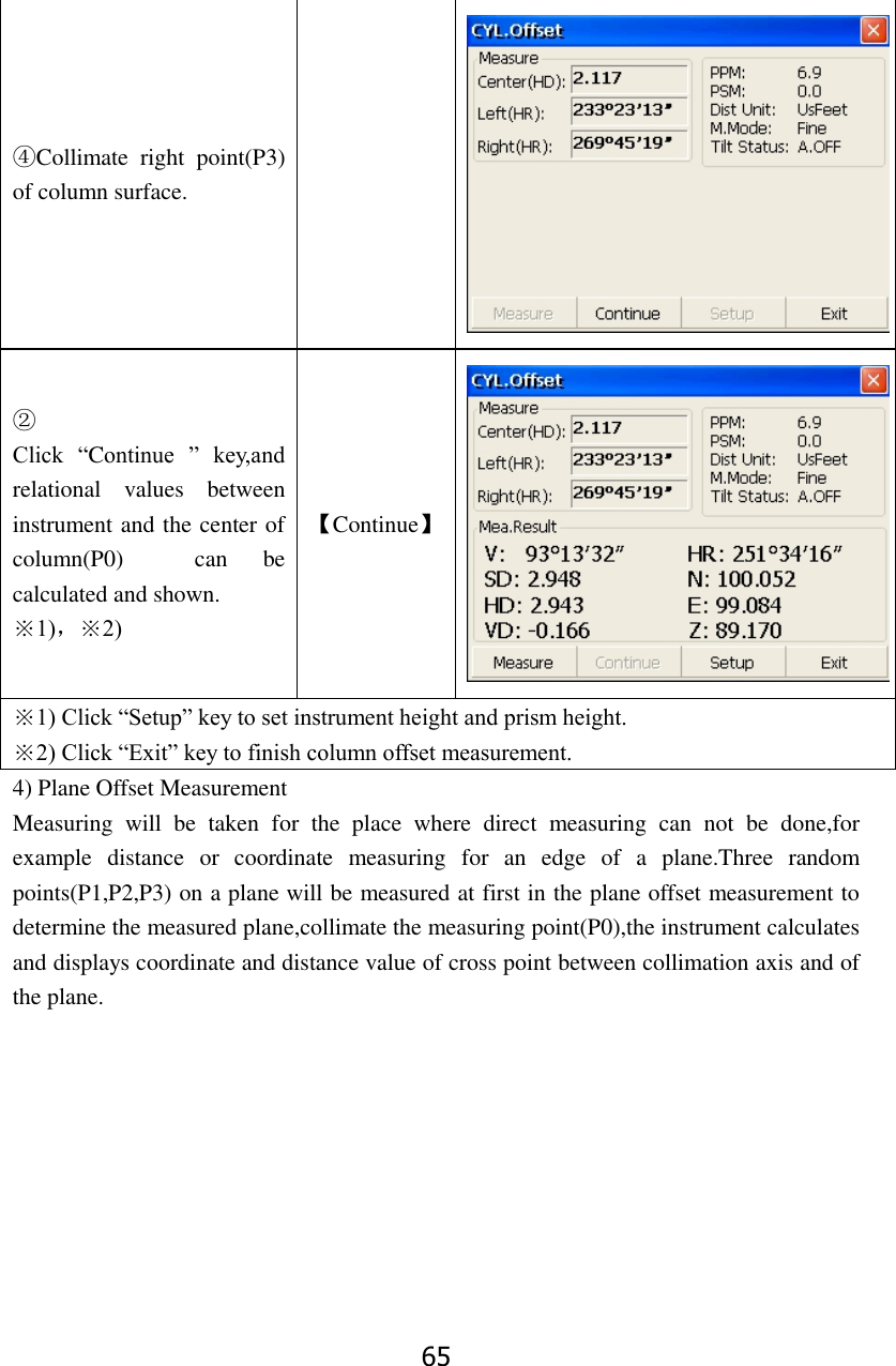
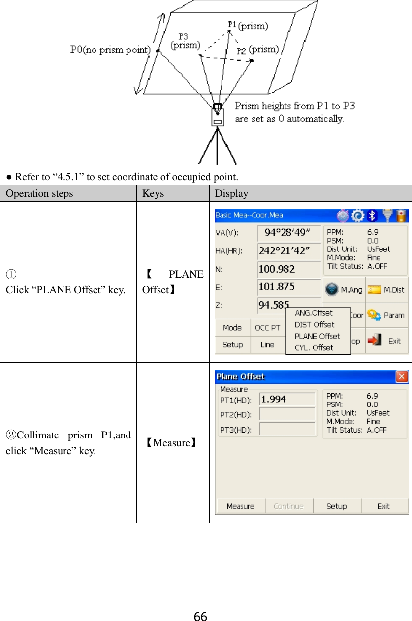
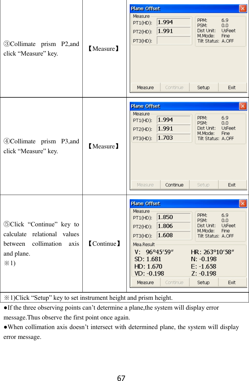
STONEX SRL R35 Total Station User Manual 8
STONEX SRL Total Station 8
UserManual.wiki
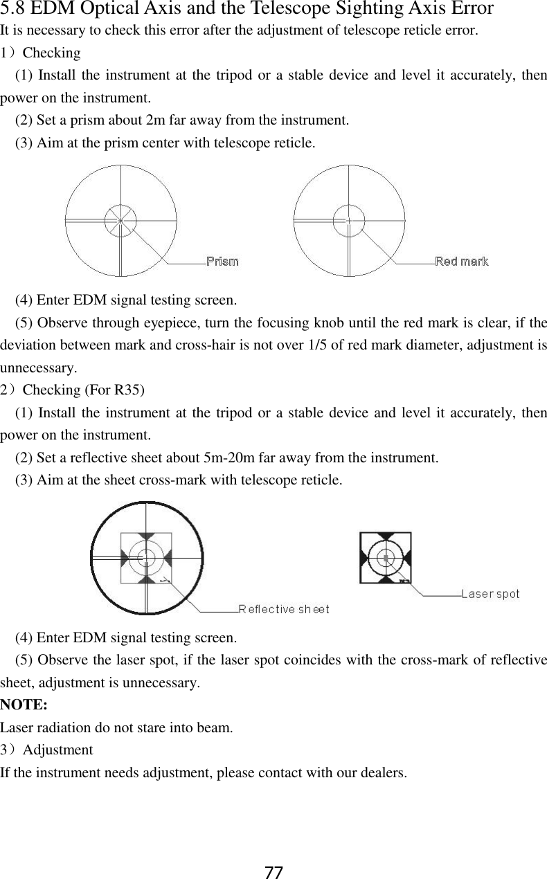
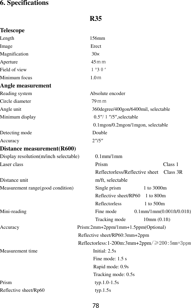
>
STONEX SRL
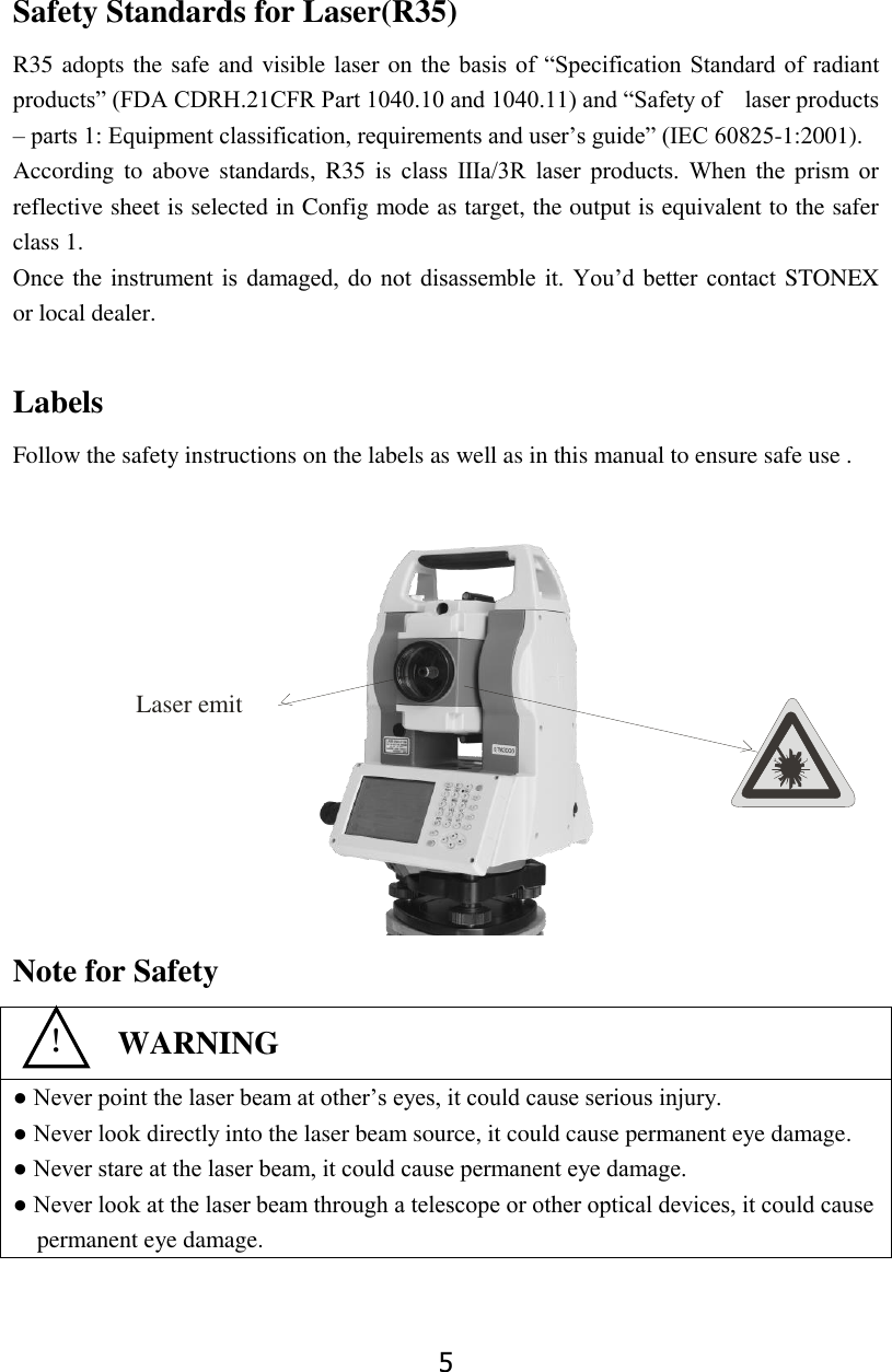
>
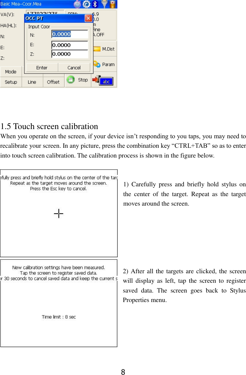
R35 User Manual
User manual
Navigation menu
Upload a User Manual
Namespaces
Wiki Guide
HTML
PDF
Info
Views
User Manual
Discussion / Help
Navigation