Samsung Electronics Co GTY3400 Cellular/ PCS GSM/ EDGE/ WCDMA Module User Manual 2
Samsung Electronics Co Ltd Cellular/ PCS GSM/ EDGE/ WCDMA Module Users Manual 2
UserManual.wiki
>
Samsung Electronics Co
>
GTY3400 User Manual
>
Users Manual 2
Contents
1.
Users Manual 1
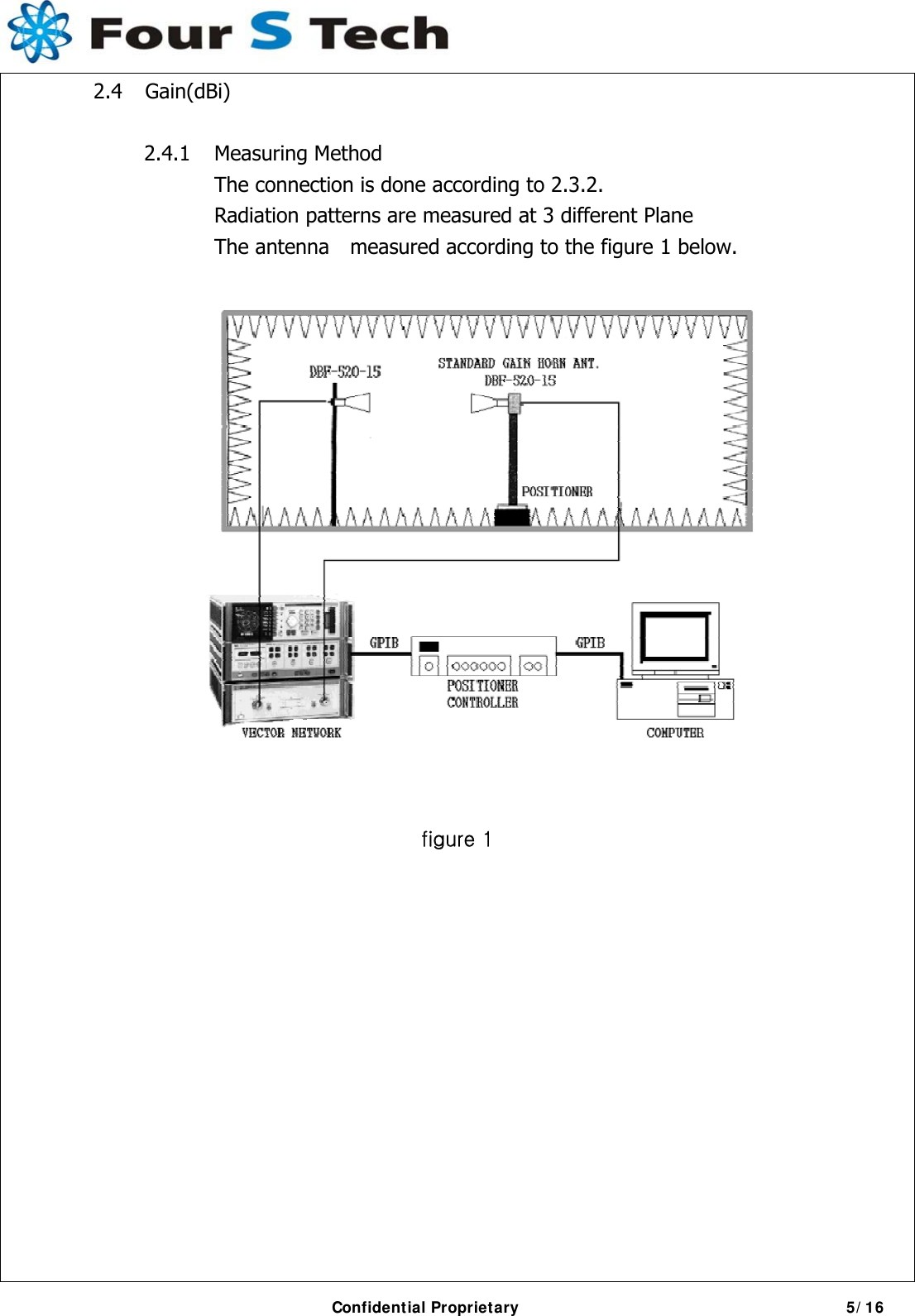
2.
Users Manual 2
Users Manual 2
Navigation menu
Upload a User Manual
Namespaces
Wiki Guide
HTML
PDF
Info
Views
User Manual
Discussion / Help
Navigation
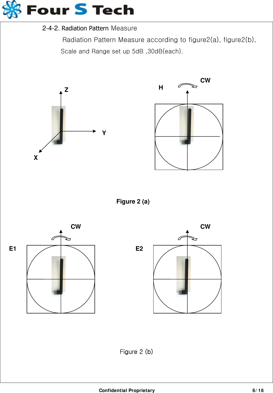
![2-4-3 Typical values in maximum direction Peak Gain [dBi] Avg. Gain [dBi] Freq. 3DVHsum H E1 E2 3DVHsum H E1 E2 - Antenna Matching Value Confidential Proprietary 7/16 0 ohm Open Open](https://usermanual.wiki/Samsung-Electronics-Co/GTY3400.Users-Manual-2/User-Guide-1455173-Page-7.png)