Samsung Electronics Co S760 Notebook Computer User Manual Version 0 Maverick Change from Matrix
Samsung Electronics Co Ltd Notebook Computer Version 0 Maverick Change from Matrix
Contents
- 1. user manual 1 of 3
- 2. user manual 2 of 3
- 3. user manual 3 of 3
user manual 3 of 3
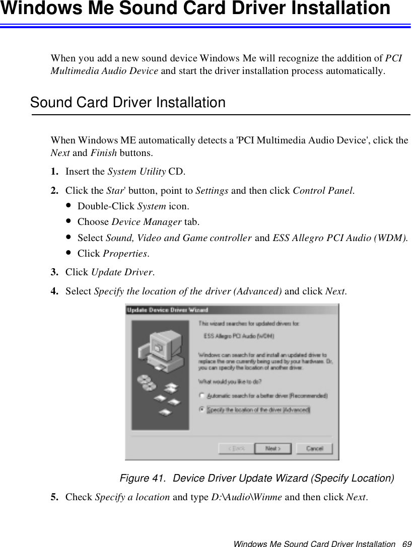
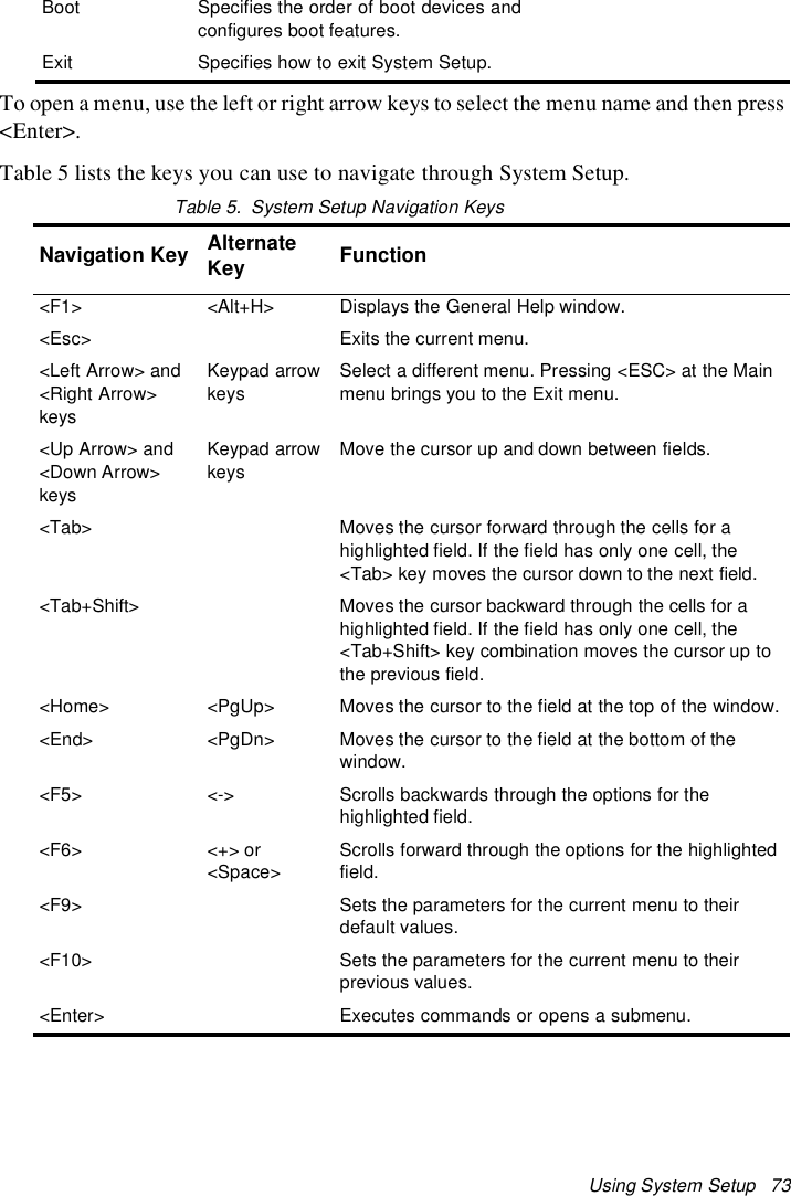
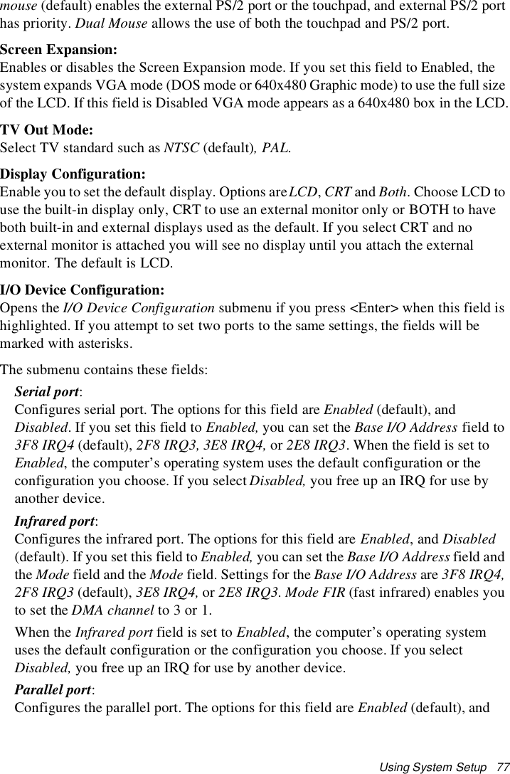
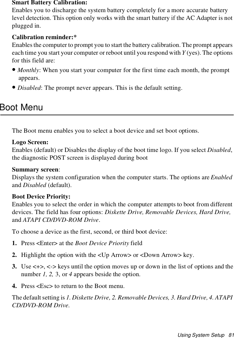
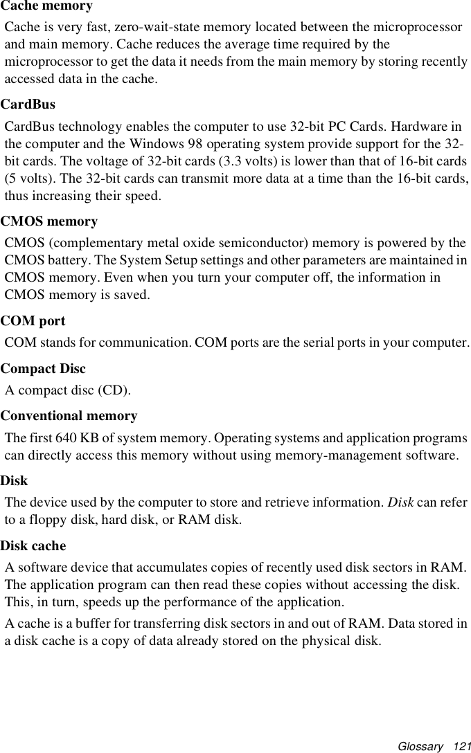
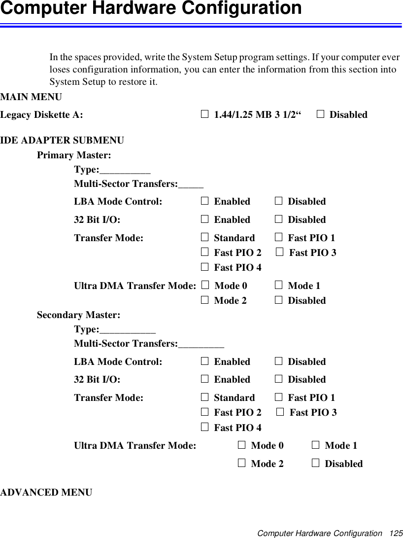
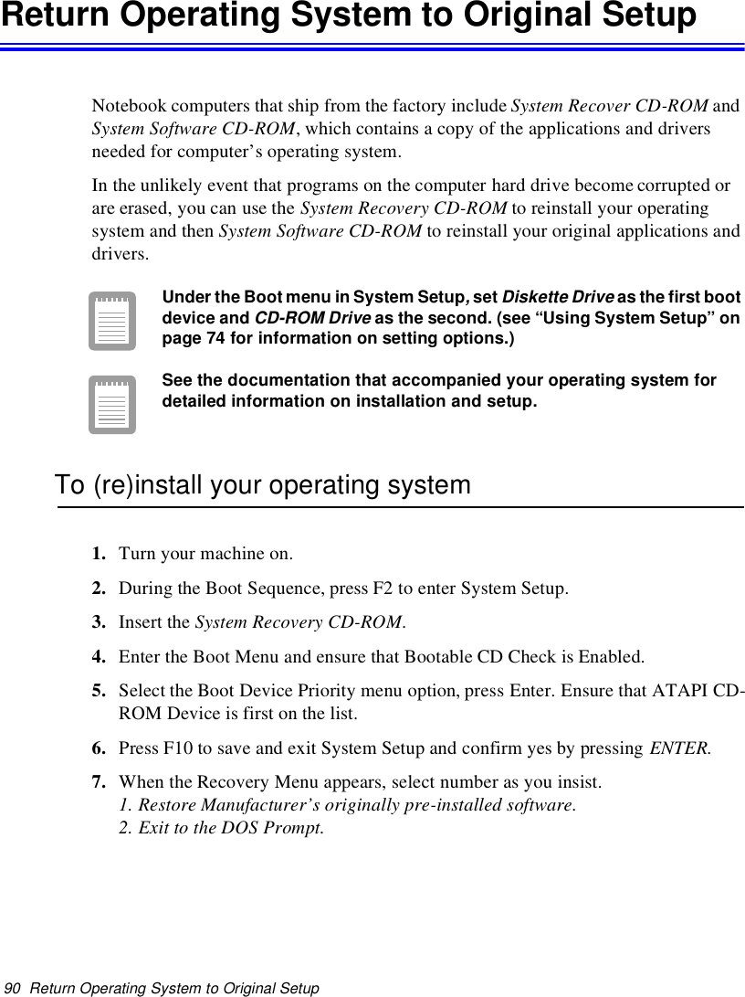
![88 Creating a Save to Disk PartitionCreatingaSavetoDiskPartitionSave to Disk Partition: [Not Windows Me]It enables you to store data from the system and video memory to hard driveduring Save To Disk mode for computer shipped with Windows 95, 98installed. Windows Me does not need this partition.If you want to use a new hard drive to your system, you need to create a Save to DiskPartition area on the new hard drive.See the below notes and cautions before partitioning your HDD;•Back up data files of your old hard drive.•If you do not intend to use Save to Disk mode, you do not need to create a Save toDisk Partition.•For system boot with CD-ROM, under the Boot menu in System setup, set BootableCD Check to Enabled and set Boot Device Priority ordered starting from [DVD/CD-ROM]. Use DVD Software CD in this process.•Before you set partition and format HDD, set Fixed Disk Boot Sector to Normal inSecurity menu of System setup.To create FDISK1. Set the system boot with CD-ROM, press <F8> key to boot with “Safe modecommand prompt only”.2. Operate Fdisk.exe, type “A:\>fdisk” and press Enter.3. When 'Do you wish to enable large disk support (Y/N)...?' shows, select Y and pressEnter.4. Select '1. Create DOS partition or Logical DOS Drive' field in [FDISK Options].5. Select 'Create Primary DOS Partition' field in [Create DOS Partition or LogicalDOS Drive] and press Enter to start creating 'Primary DOS Partition'.6. ’Do you wish to use the maximum available size for a Primary DOS Partition andmake the partition active (Y/N)...?' shows, then select N to divide HDD into severaldrives or using Save to Disk mode. If you select Y, it means you are not using Saveto Disk Partition and use HDD sector as active DOS only.7. Type the partition size in the blank of 'Enter partition size in Mbytes or percent ofdisk space (%) to create a Primary DOS Partition...:[ ]' and press Enter.](https://usermanual.wiki/Samsung-Electronics-Co/S760.user-manual-3-of-3/User-Guide-132877-Page-25.png)
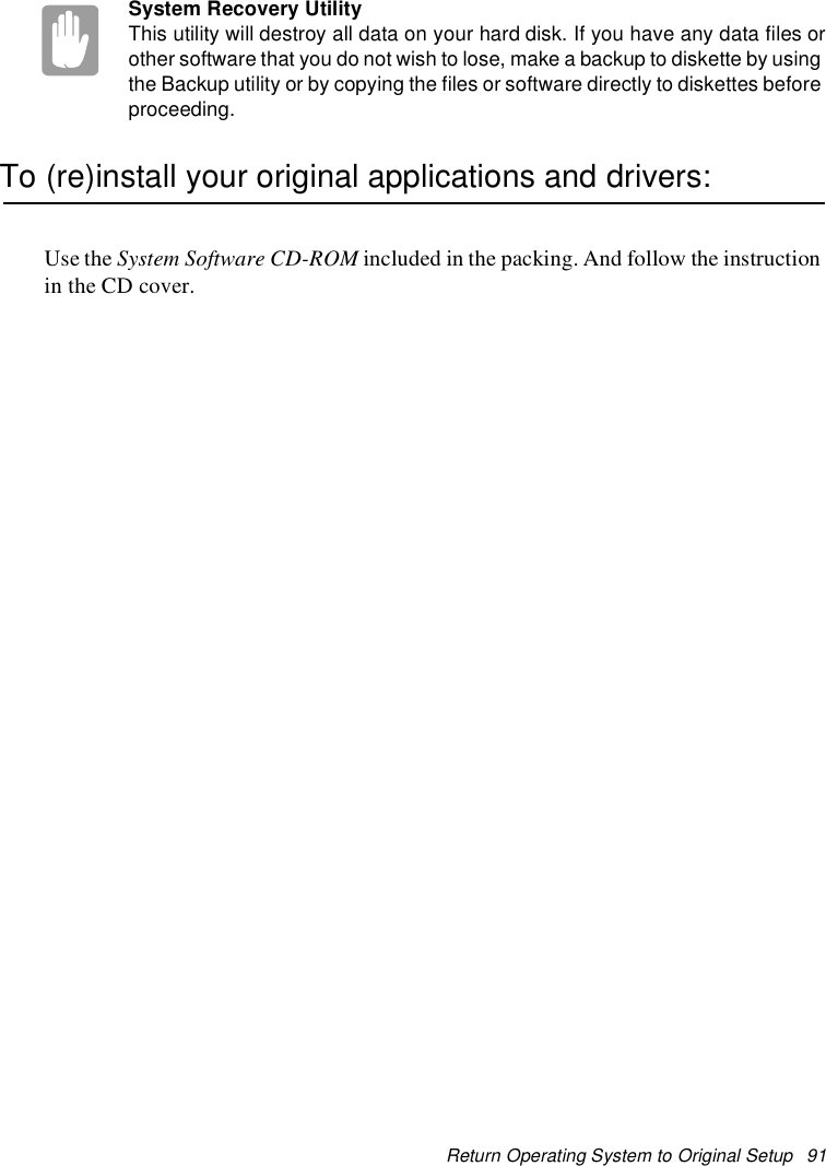
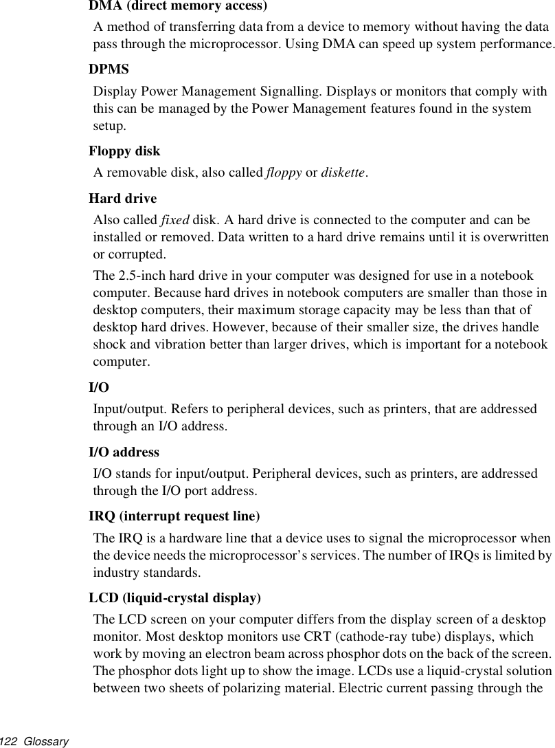
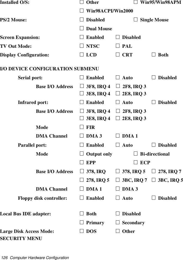
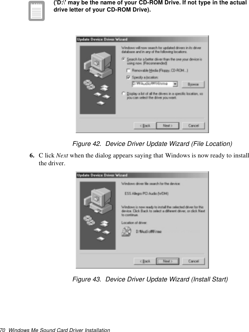
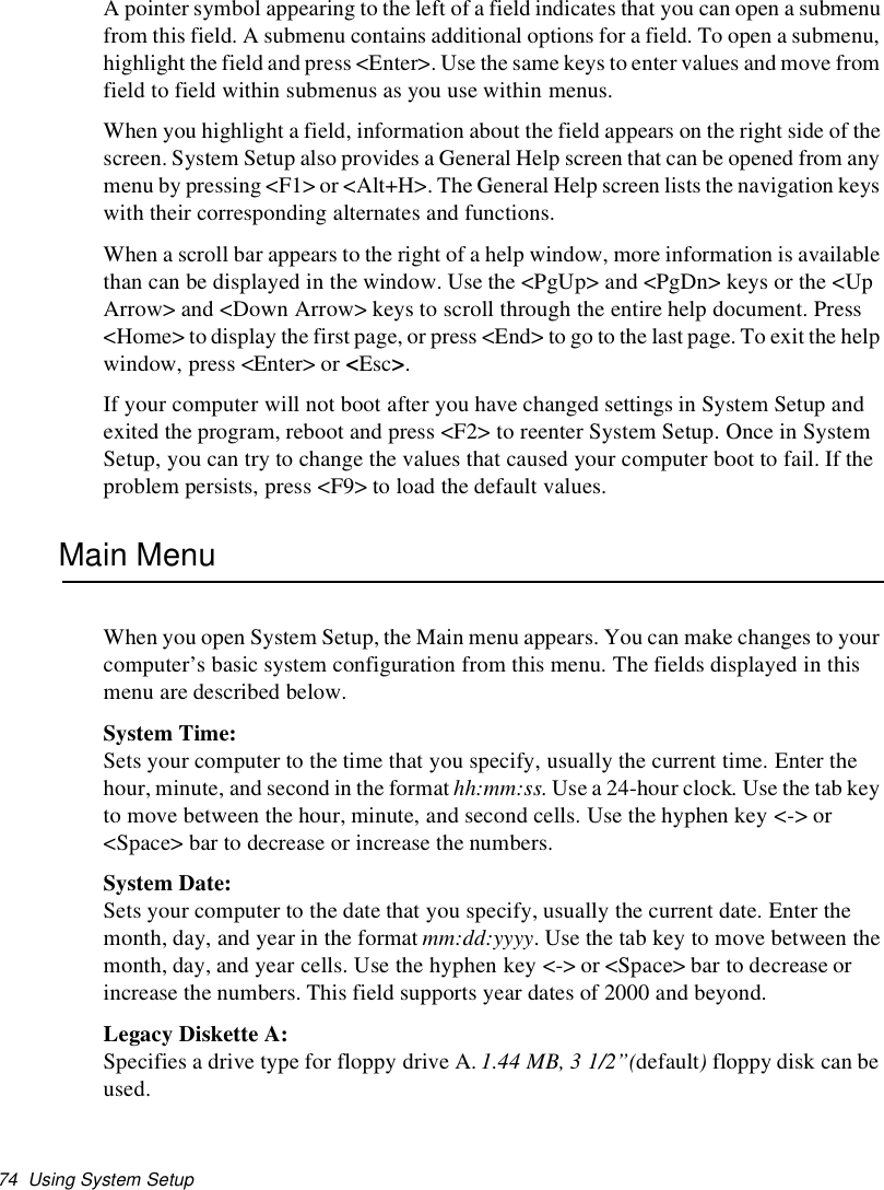
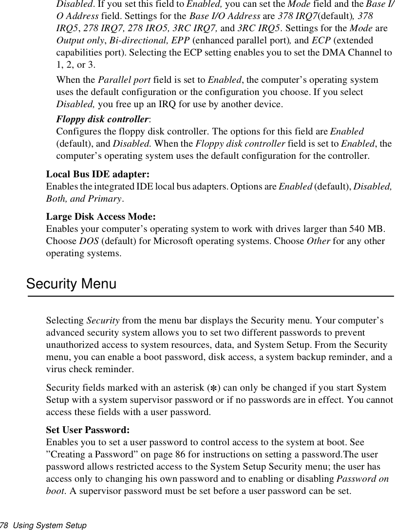
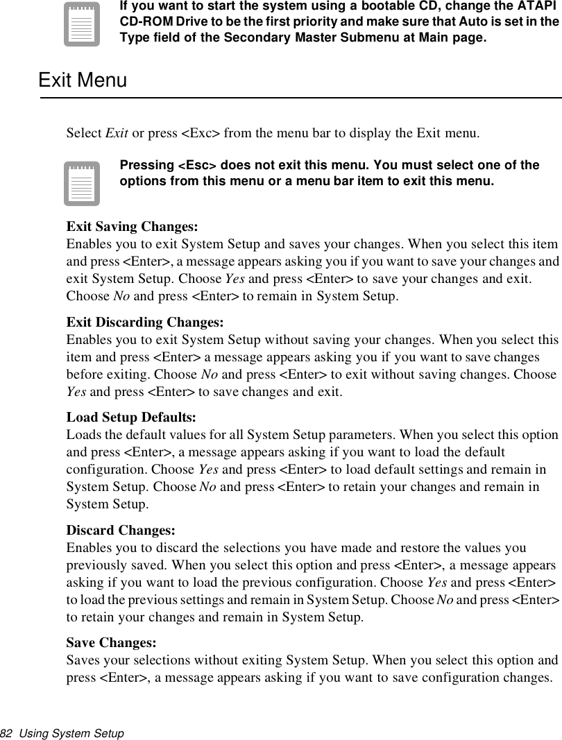
![Video Features and Configuration 952. Select Settings and click on Control Panel, double click on Display. The DisplayProperties window appears.3. Select Settings tab.4. Click the Advanced button. The properties screen for your currently installed videodriver appears.5. Select the Adapter menu.6. Click the Change button. The Update Device Driver Wizard window appears.7. Click the Next button.8. Select Display a list of all the drivers in a specific location, so you can select thedriver you want. Click the Next button.9. Click the Have disk button. If the driver is on a floppy disk insert it into the floppydrive. Click the Browse button and locate driver you want to install. Click the OKbutton.10.Select the new driver in the Select Device screen and click the Ok button.11.Click the Next button to install the new driver and follow any directions on thescreen to finish setting the display properties.Windows Me ReinstallationIf your system crashes and you have to reinstall Windows Me you will have toreinstall the S3 Savage IX Video Driver.To reinstall the driver complete the following steps.1. Insert System Recovery Disk 2 CD to CD-ROM drive.2. Click Start > Settings > Control Panel > double click on the Display icon.3. Click Settings >Advanced in Display Properties.4. ClickontheAdapter tab and click Change.5. The Update Device Driver Wizard window appears.6. Select Specify the location of the driver [Advanced] and click Next7. Select Specify a location and input "D:\Driver\Graphics\WinME".8. Next9. Next](https://usermanual.wiki/Samsung-Electronics-Co/S760.user-manual-3-of-3/User-Guide-132877-Page-32.png)
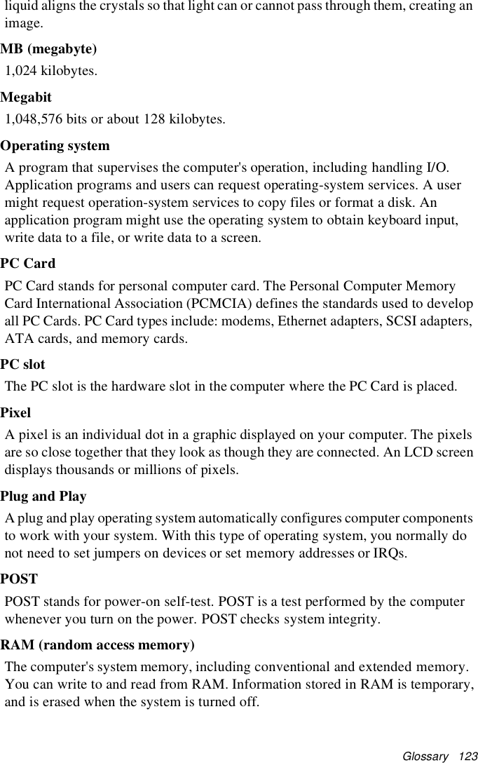
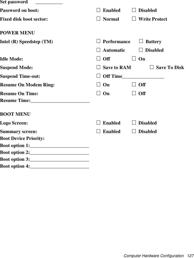
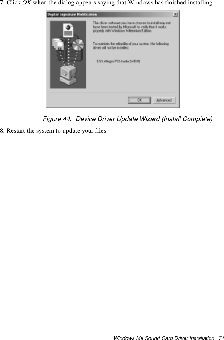
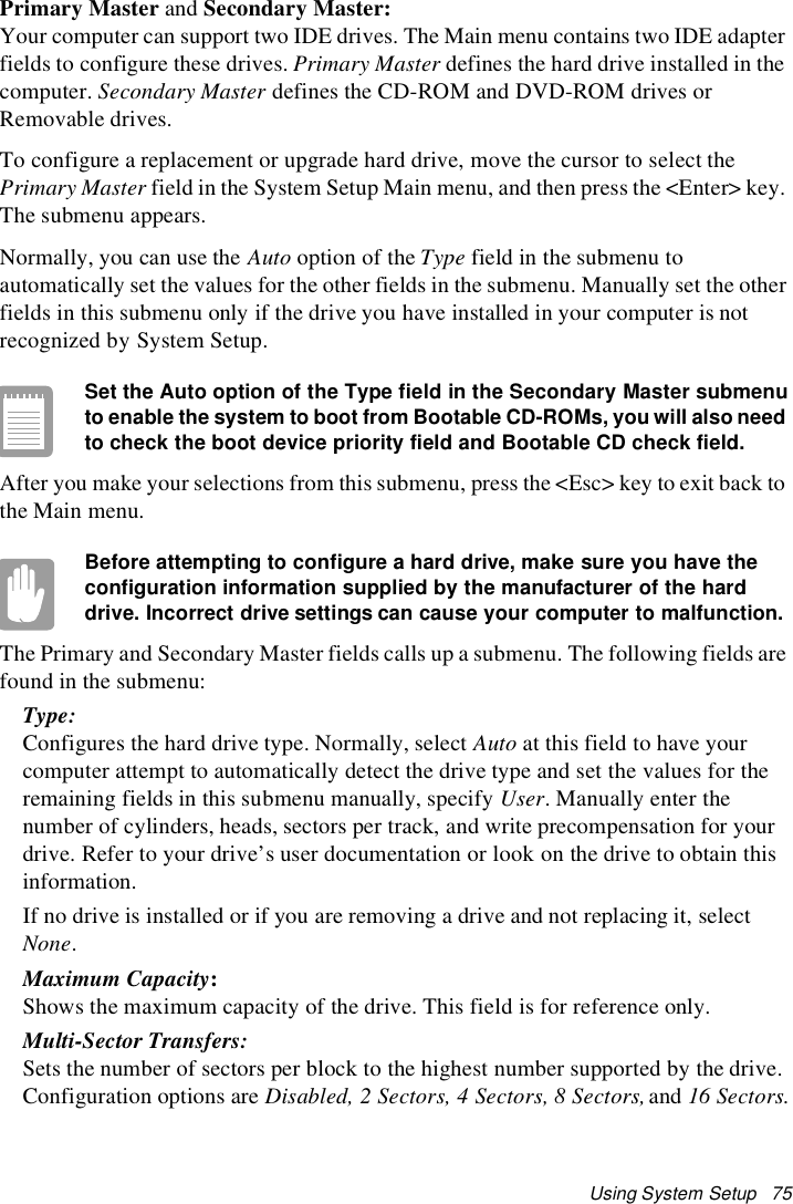
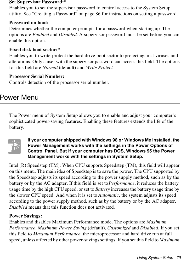
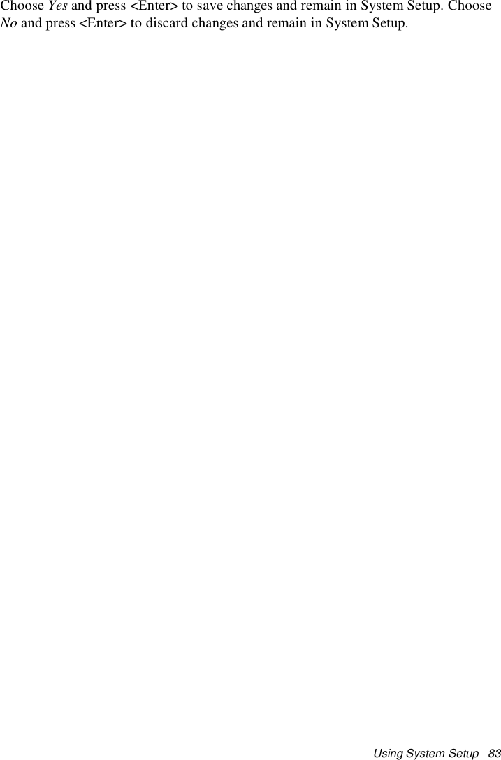
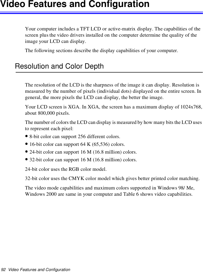
![Using Options 107Using OptionsYou can order the following options for your Notebook computer from your authorizedreseller:•An extra AC adapter.•An extra battery pack. [Standard or large size]•An upgraded hard drive. Optional hard drives are available to fit in the hard drivecompartment or the Multi-Bay docking station. [IBM HDD is currently supported]•64,128 and 256 MB SDRAM memory modules that enable you to upgrade yourcomputer’s memory to a maximum of 320MB.•A CD-ROM drive module. [5.25" Multi-bay]•A DVD-ROM drive module. [5.25" Multi-bay]•A CD-RW drive module. [5.25" Multi-bay]•A Zip 250 Mb drive. [3.5" Multi-bay]•Docking options that enable you to use your computer like a desktop computer.The options that are available may change periodically. Contact your reseller forupdated information on current and new options.Battery PackYou can order another smart lithium-ion battery pack for your computer. See ”Usingthe Battery” on page 45 for information on the battery.Hard DrivesYou can order optional hard drives for your system. A hard drive can be installed in the3.5" compartment of the Multi-bay docking station. See ”Using the Multi-Bay DockingStation” on page 30 for information on installing a device in the Multi-Bay dockingstation.](https://usermanual.wiki/Samsung-Electronics-Co/S760.user-manual-3-of-3/User-Guide-132877-Page-44.png)
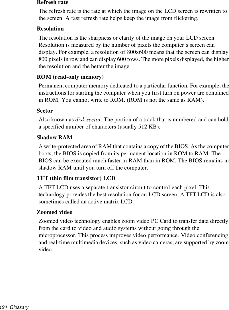
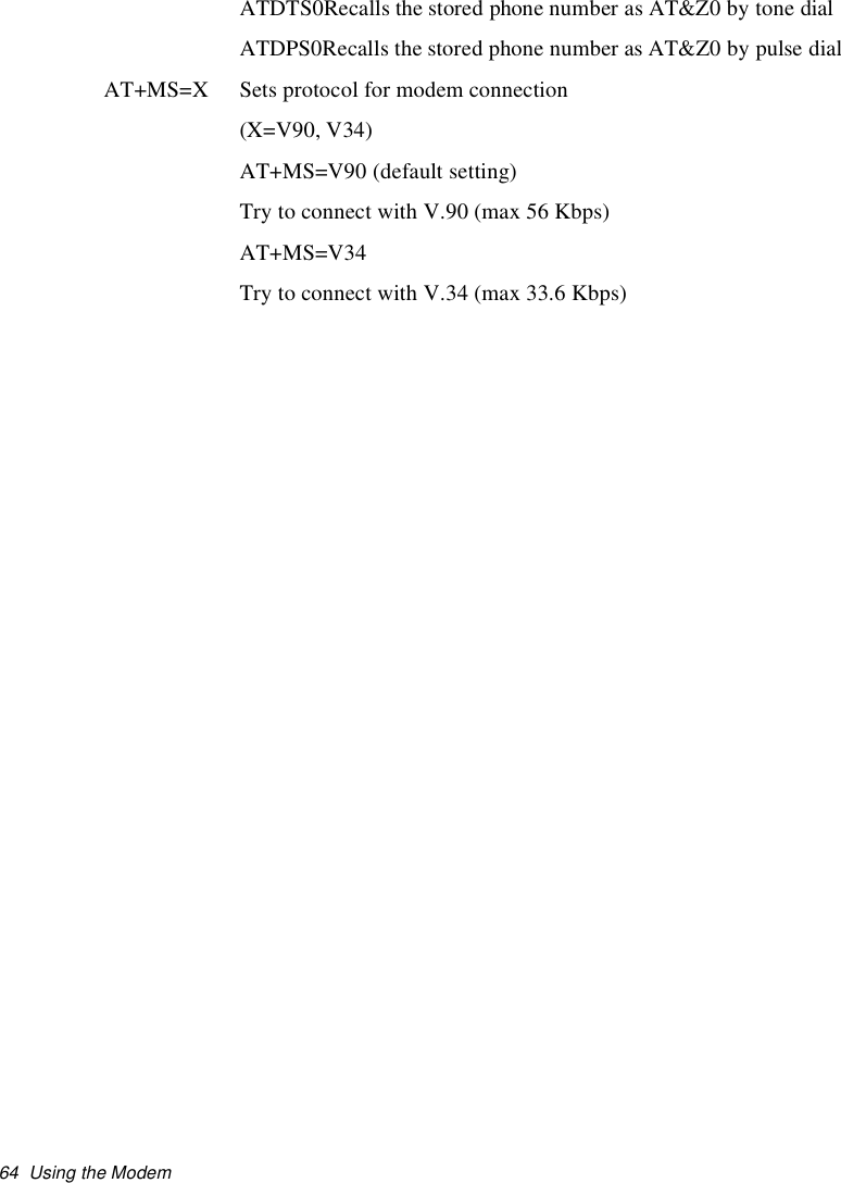
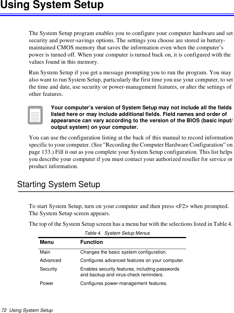
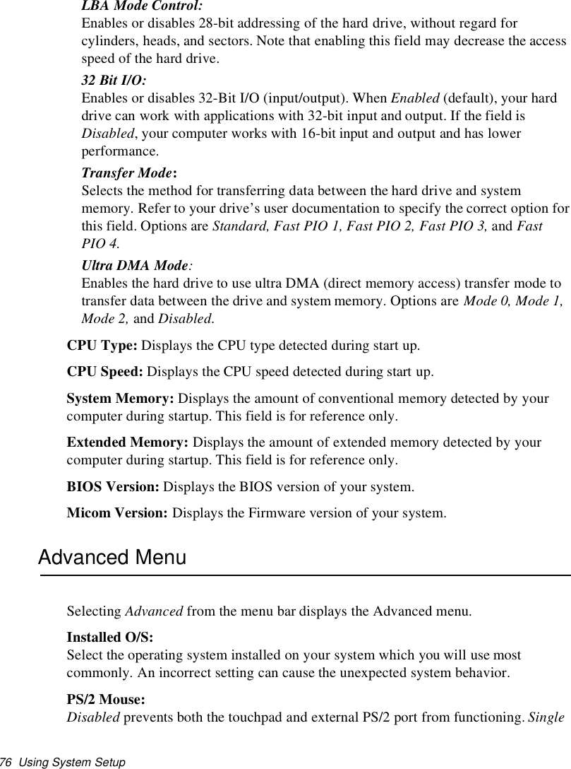
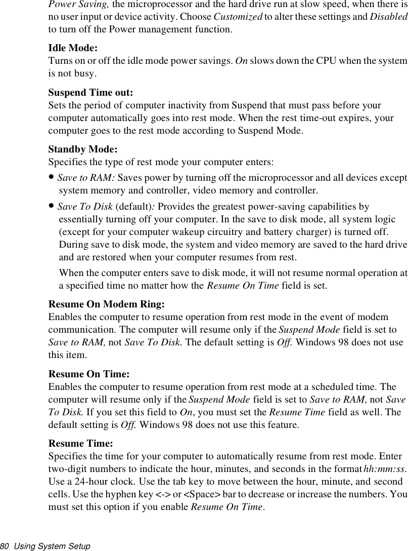
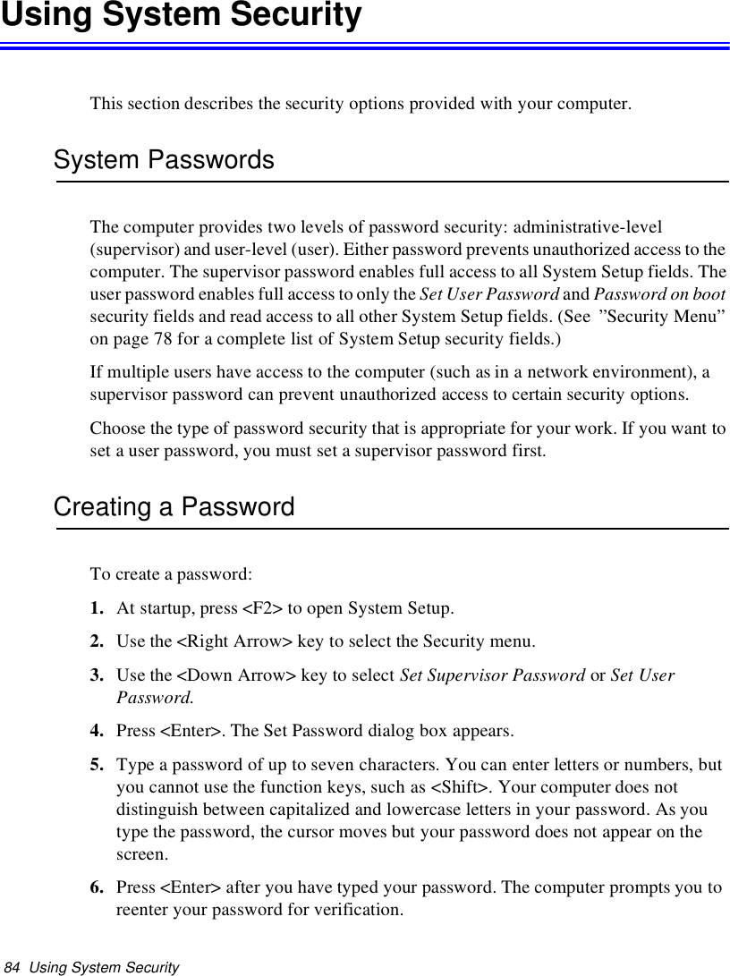
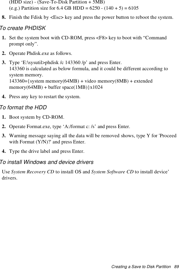
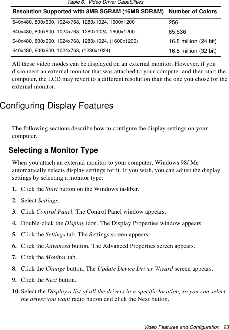
![Specifications 115SpecificationsTable 9 gives the specifications for computers.Table 8. Hardware SpecificationsDimension* LCD viewing areaLCD viewing area (12.1 TFT) 26.7 x 18.6 cmWidth [Docking Station] <Notebook> [27.4 cm] <27.3 cm>Depth [Docking Station] <Notebook> [23.0 cm] <22.7 cm>Height [Docking Station] <Notebook> [25.0 cm] <19.8 - 22.3 cm>Weight (with integrated floppy drive,Li-Ion battery & 14.1” TFT LCD & weightsaver)~3200 gEnvironmentAmbient temperature, operating 50o–90oF(10o–32oC)Ambient temperature, storage 23o–104oF(-5o–40oC)Relative humidity (noncondensing),operating20–80%Relative humidity (noncondensing), storage 5–90%Altitude, operating 0 to 8,000 ft (0 to 2,348 m)Altitude, storage 0to40,000ft(0to12,192m)Shock, operating 10 G for 11 ms half sineShock, nonoperating 60 G for 11 ms half sineLithium-Ion Smart Battery [Large]Normal Weight 0.99lb (450g)Nominal open circuit voltage 7.4 VDCCapacity, typical 53 whrCharging time, approximate, with computerturned off, typical~3.0 hrCharging time, approximate, with computerturned on, typical~5.0 hr](https://usermanual.wiki/Samsung-Electronics-Co/S760.user-manual-3-of-3/User-Guide-132877-Page-52.png)
![116 SpecificationsAverage battery life, with no powermanagement enabled~5 hrLithium-Ion Smart Battery [Small]Normal Weight 0.99lb (450g)Nominal open circuit voltage 7.4 VDCCapacity, typical 24 whrCharging time, approximate, with computerturned off, typical~3.0 hrCharging time, approximate, with computerturned on, typical~5.0 hrAverage battery life, with no powermanagement enabled~2.5 hrExternal AC AdapterOperating voltage 100-240 VACLine frequency 50-60 HzInput current 1.2 A 100 V ~ 0.6 A 240 VOutput current 3.2 AOutput voltage 12.0 VDC](https://usermanual.wiki/Samsung-Electronics-Co/S760.user-manual-3-of-3/User-Guide-132877-Page-53.png)