Samsung Electronics Co SLS-BD104Q1 WiMAX / TD-LTE Remote Radio Head User Manual
Samsung Electronics Co Ltd WiMAX / TD-LTE Remote Radio Head
UserManual.wiki
>
Samsung Electronics Co
>
SLS-BD104Q1 User Manual
>
User Manual
Contents
1.
Installation Manual
2.
User Manual
User Manual
Navigation menu
Upload a User Manual
Namespaces
Wiki Guide
HTML
PDF
Info
Views
User Manual
Discussion / Help
Navigation
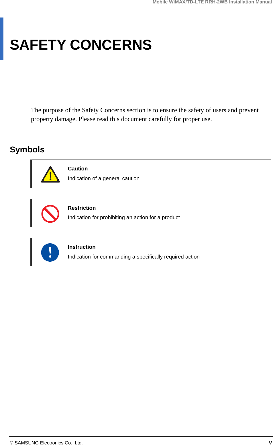
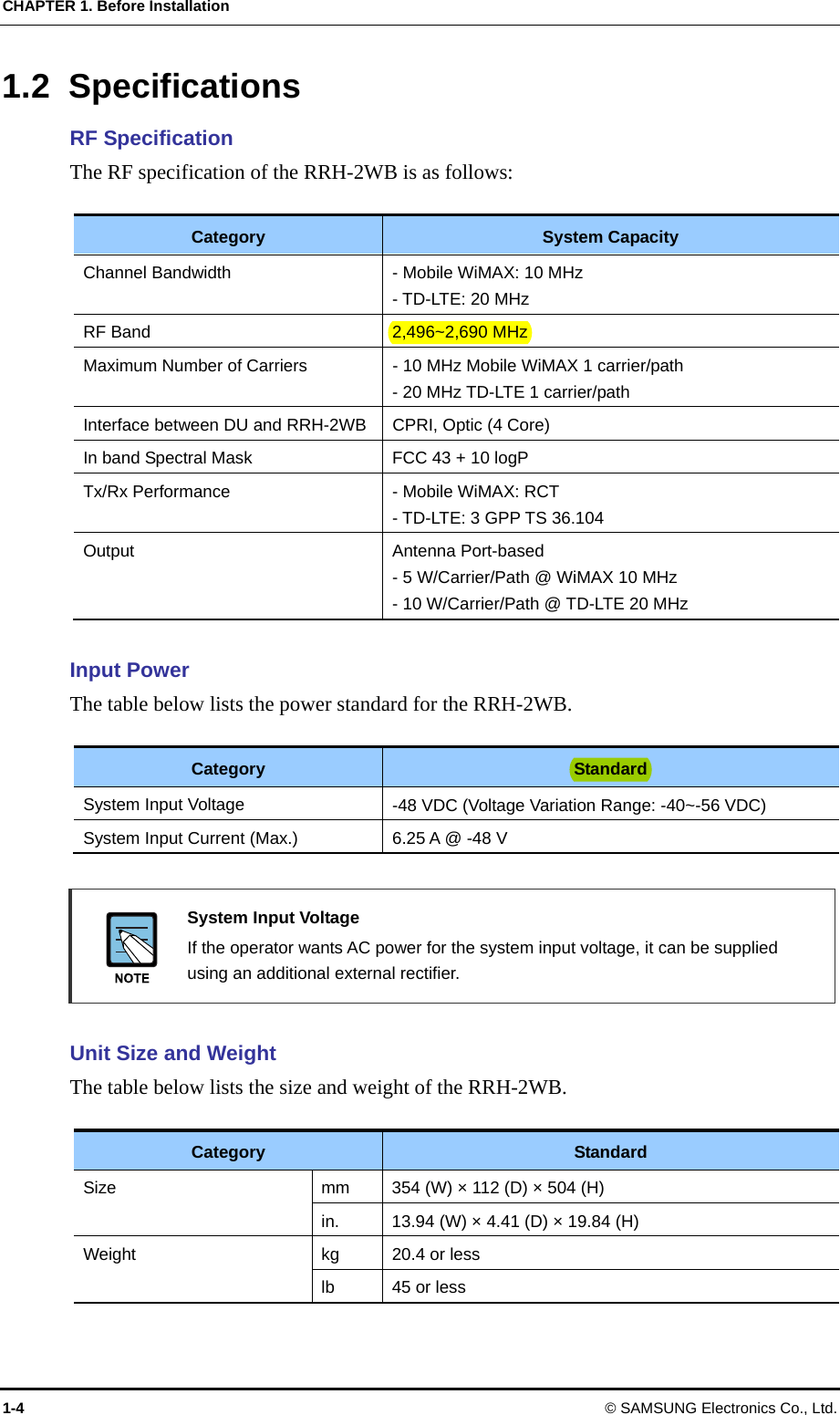
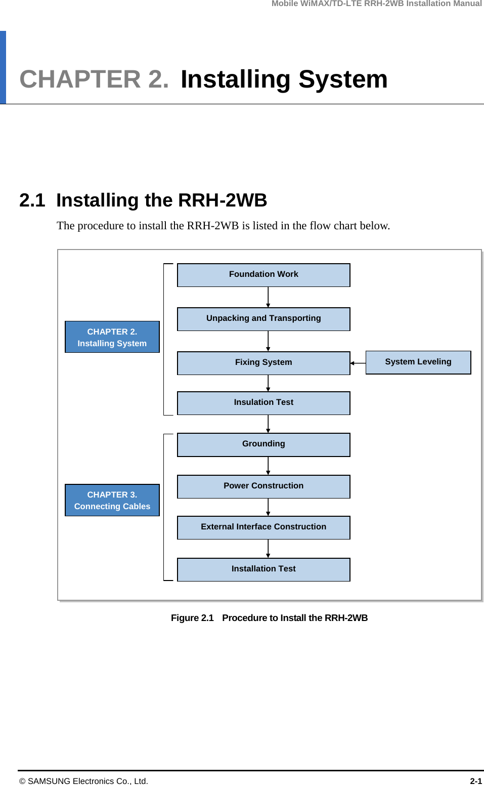
![Mobile WiMAX/TD-LTE RRH-2WB Installation Manual © SAMSUNG Electronics Co., Ltd. 1-1 CHAPTER 1. Before Installation 1.1 System Configuration and Structure RRH-2WB Configuration The configuration of RRH-2WB is as follows: Figure 1.1 RRH-2WB Configuration [Bottom View][Front View] [Right View] [Top View] [Left View] 143.5 (5.65) 354 (13.94)370 (14.57)504 (19.84) 520 (20.47) 112 (4.41) Unit: mm (in.)](https://usermanual.wiki/Samsung-Electronics-Co/SLS-BD104Q1.User-Manual/User-Guide-1883664-Page-19.png)
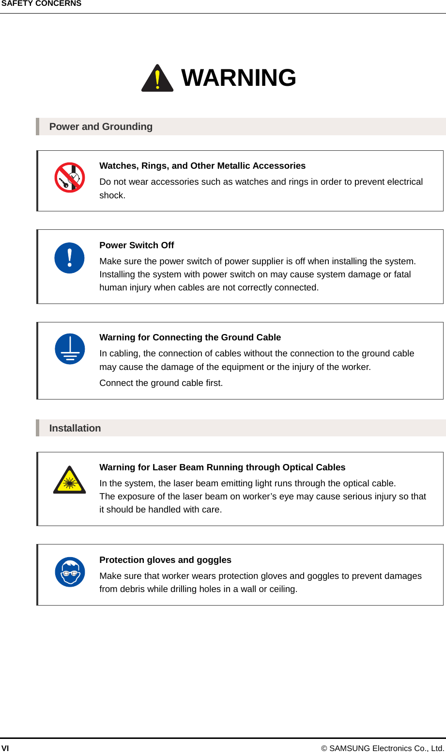
![CHAPTER 1. Before Installation 1-2 © SAMSUNG Electronics Co., Ltd. When the solar shield is assembled, the RRH-2WB should be configured as follows: Figure 1.2 RRH-2WB Configuration When the Solar Shield is Assembled [Bottom View] [Front View] [Right View] [Top View][Left View] 169 (6.65) 386.5 (15.22)576 (22.68) Unit: mm (in.)](https://usermanual.wiki/Samsung-Electronics-Co/SLS-BD104Q1.User-Manual/User-Guide-1883664-Page-20.png)
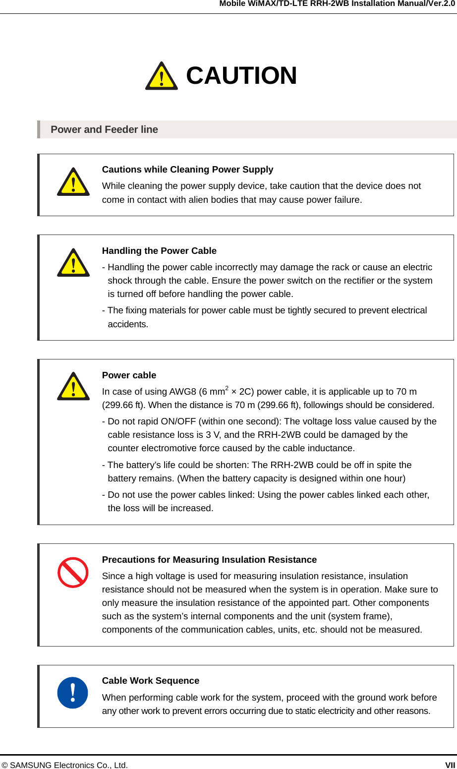
![Mobile WiMAX/TD-LTE RRH-2WB Installation Manual/Ver.2.0 © SAMSUNG Electronics Co., Ltd. 1-3 RRH-2WB External Interface The external interface of RRH-2WB is as follows: Figure 1.3 RRH-2WB External Interface [Bottom View] ATN_3 ATN_0 ATN_1ATN_2-48 V IN Optic RET Frame Ground Debug](https://usermanual.wiki/Samsung-Electronics-Co/SLS-BD104Q1.User-Manual/User-Guide-1883664-Page-21.png)
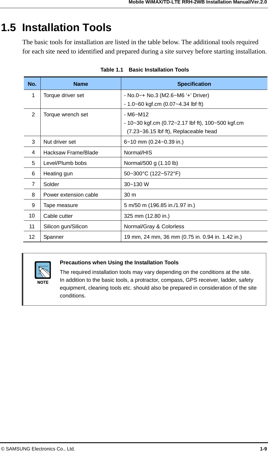
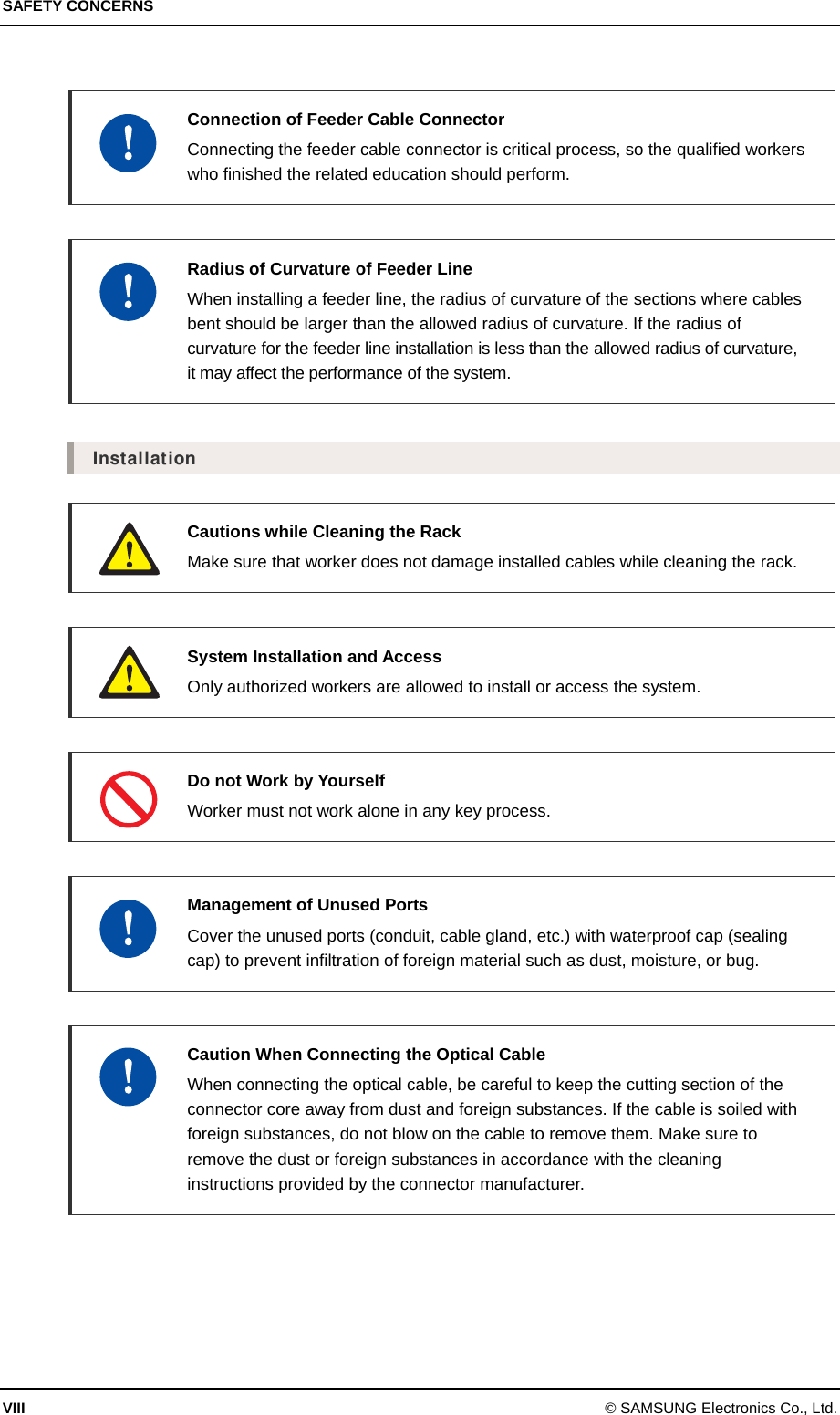
![CHAPTER 2. Installing System 2-2 © SAMSUNG Electronics Co., Ltd. 2.2 Foundation Work 2.2.1 System Arrangement A certain distance must be secured around the RRH-2WB in each direction for installation and maintenance. Table 2.1 Recommended Distances for System Category Recommended Distances Front/Rear 800 mm (31.50 in.) or more Side 200 mm (7.87 in.) or more Top/Bottom (In case of Pole Type) 1,000 mm (39.37 in.) or more Figure 2.2 RRH-2WB Installation Space System Installation Spaces The space specifications in the Figure above apply when the pole diameter is 101.6 mm (4 in.). The dimensions may vary depending on the diameter of the pole. Pole[76.3~114.3 (3~4.5)] [Pole Type-3 RRH] 630.5 (24.82) 720.5 (28.37) Pole[76.3~114.3 (3~4.5)] [Pole Type-1 RRH]390 (15.35) 140 (5.51) 200 (7.87) 390 (15.35)[Tower Type]200 (7.87) TowerUnit: mm (in.)](https://usermanual.wiki/Samsung-Electronics-Co/SLS-BD104Q1.User-Manual/User-Guide-1883664-Page-30.png)
![Mobile WiMAX/TD-LTE RRH-2WB Installation Manual/Ver.2.0 © SAMSUNG Electronics Co., Ltd. 2-3 2.2.2 Marking and Drilling System marking helps install the system in a precise location by marking the locations of the system, anchor bolts, and cable racks on the floors, walls, and ceilings. When marking is completed, drill holes for anchor bolts. 1) On the location of the system installation, mark the positions of the equipment and anchor bolts as shown in the Figure below. 2) Drill holes to insert the anchor bolts and cover the holes with acetate tape before installing the system. Table 2.2 Anchor Bolt Drill Bits and Hole Depth Mounting Method Anchor Bolt Drill Bits Hole Depth Wall mount M6 10 mm (0.39 in.) 33 mm (1.3 in.) Figure 2.3 RRH-2WB Marking Anchor Bolt Hole[Rear View] 168 (6.61) 370 (14.57) 576 (22.68) 520 (20.47) 330 (12.99) 390 (15.35) Unit: mm (in.)](https://usermanual.wiki/Samsung-Electronics-Co/SLS-BD104Q1.User-Manual/User-Guide-1883664-Page-31.png)
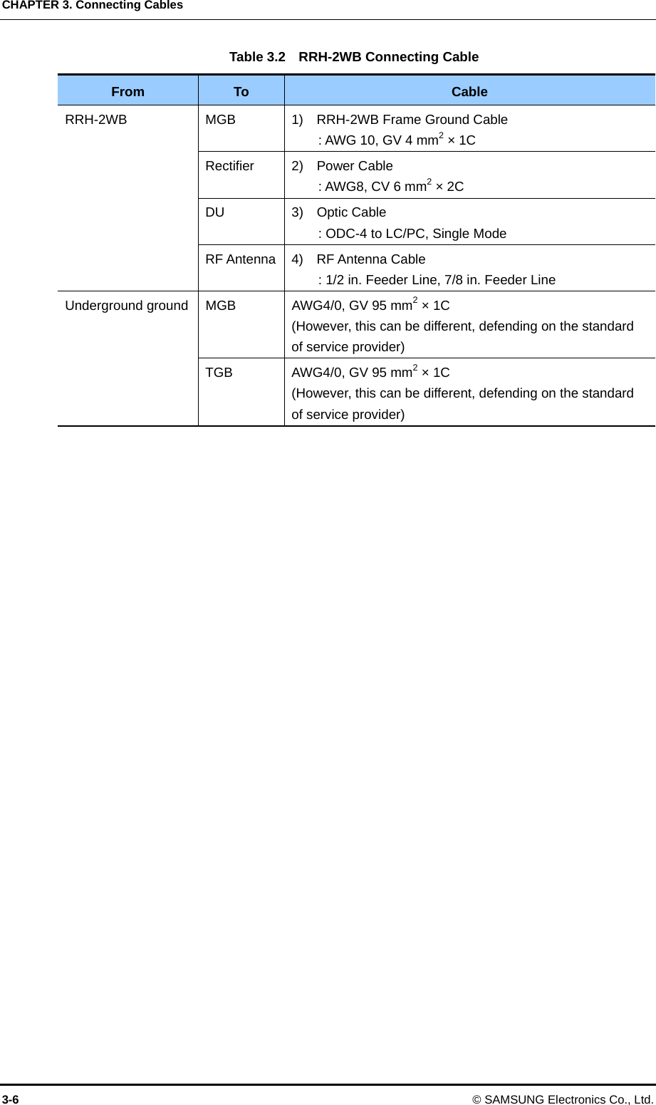
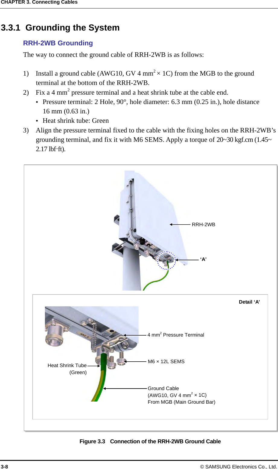
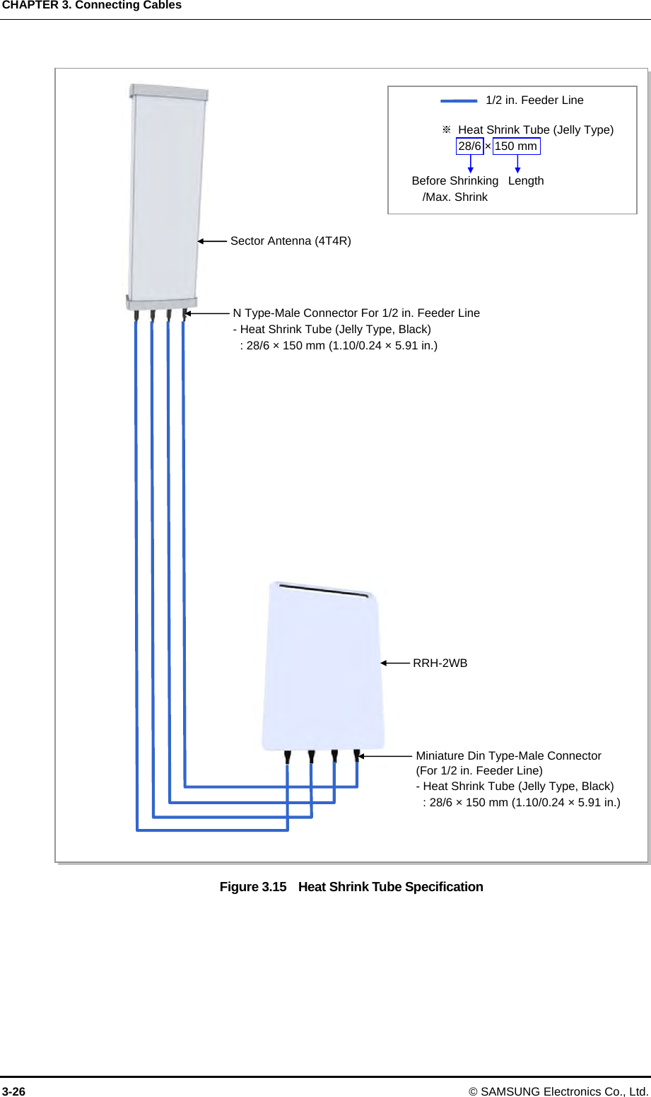
![Mobile WiMAX/TD-LTE RRH-2WB Installation Manual/Ver.2.0 © SAMSUNG Electronics Co., Ltd. 3-5 3.2 Cabling The cabling diagram of the RRH-2WB is as follows: Figure 3.2 Cabling Diagram 1) RRH-2WB Frame Ground Cable [DU] [Rectifier] [RF Antenna] [MGB] 4) RF Antenna Cable TGB Ground Cable[TGB] Ground Kit※ TGB and Ground Kit are used when using the 7/8 in. feeder line or more.3) Optic Cable (for DU) 2) Power Cable](https://usermanual.wiki/Samsung-Electronics-Co/SLS-BD104Q1.User-Manual/User-Guide-1883664-Page-67.png)
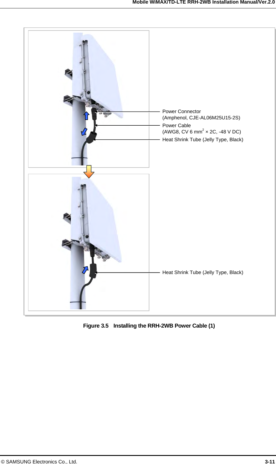
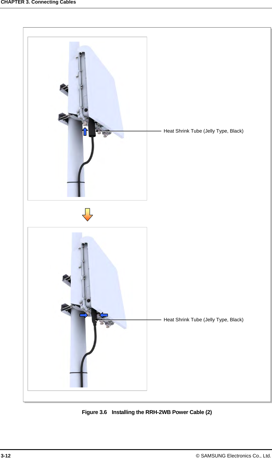
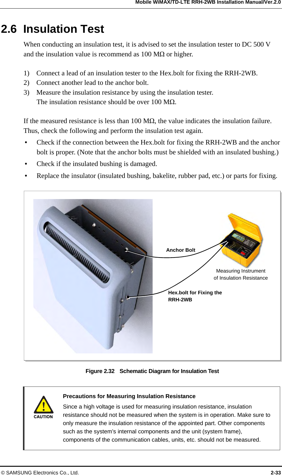
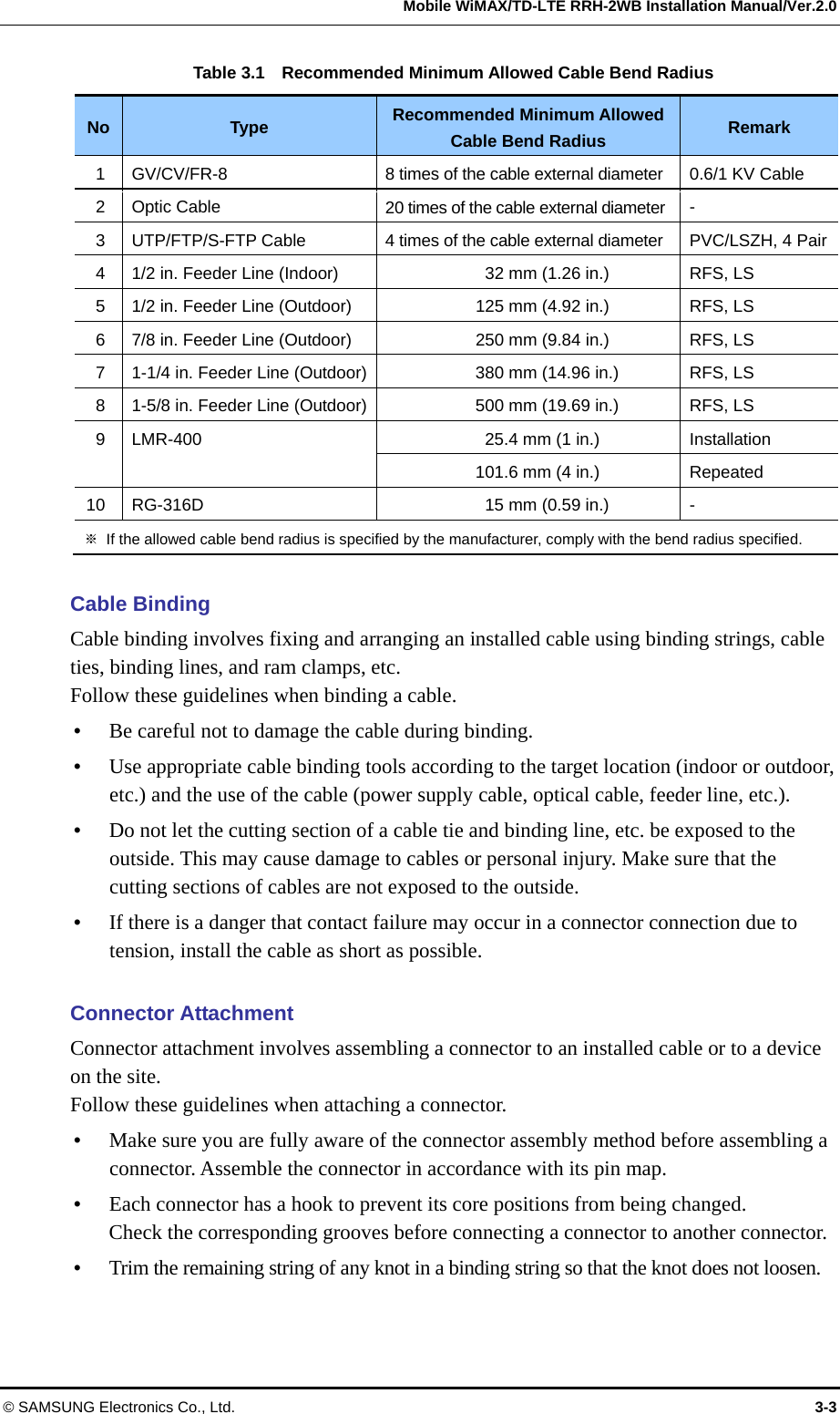
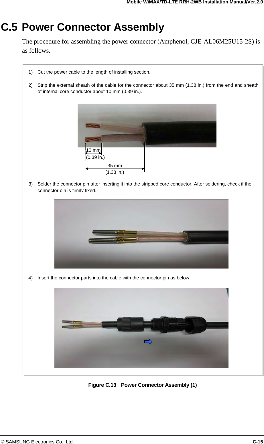
![Mobile WiMAX/TD-LTE RRH-2WB Installation Manual/Ver.2.0 © SAMSUNG Electronics Co., Ltd. 3-13 [RRH-2WB Power Cable Side]C D Circuit Breaker Installation Circuit breaker of slow blow type should be installed to the power line which is connected from the rectifier (or power distributor) to the system in order to supply the power stably. The capacity of -48 VDC circuit breaker is 20 A. Power cable In case of using AWG8 (6 mm2 × 2C) power cable, it is applicable up to 70 m (299.66 ft). When the distance is 70 m (299.66 ft), followings should be considered. - Do not rapid ON/OFF (within one second): The voltage loss value caused by the cable resistance loss is 3 V, and the RRH-2WB could be damaged by the counter electromotive force caused by the cable inductance. - The battery’s life could be shorten: The RRH-2WB could be off in spite the battery remains. (When the battery capacity is designed within one hour) - Do not use the power cables linked: Using the power cables linked each other, the loss will be increased. Figure 3.7 Power Cable Connector Table 3.3 Amphenol CJE-AL06M25U15-2S Power Connector Pin Map Pin No. Description Power Cable Color (CV 6 mm2 × 2C) Heat Shrink Tube Color C -48 V Black Blue D Return White Red Power Cable Color In the table above, the cable color is based on the inner wire of the CV 6 mm2 × 2 core cable. The color of the inner wires may vary depending on the type and manufacturer of the cable used.](https://usermanual.wiki/Samsung-Electronics-Co/SLS-BD104Q1.User-Manual/User-Guide-1883664-Page-75.png)
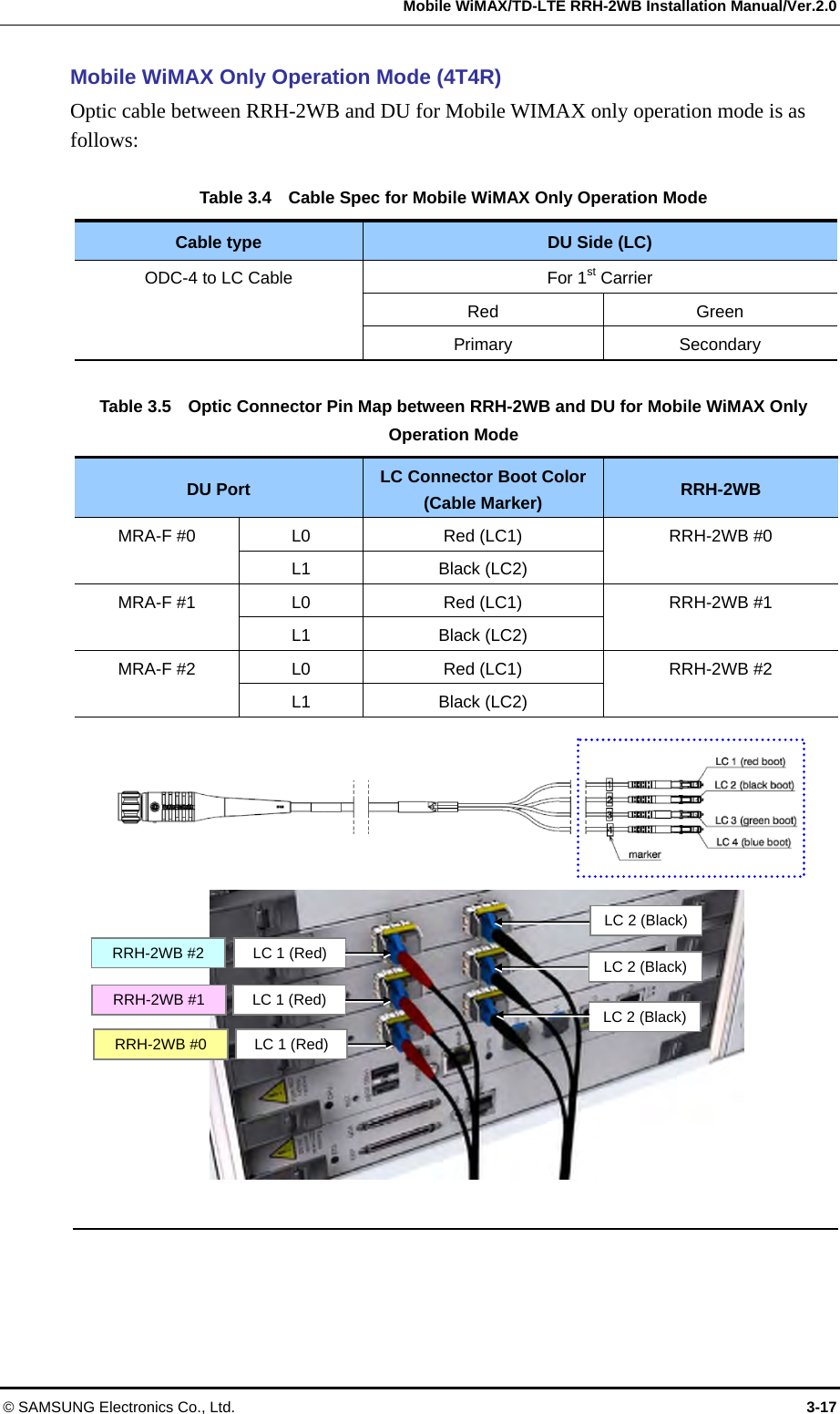
![CHAPTER 3. Connecting Cables 3-16 © SAMSUNG Electronics Co., Ltd. Figure 3.9 Optic Cable Connector between DU and RRH-2WB_RRH-2WB side [RRH-2WB-side Connector: ODC-4 (ODCP-Z/M-A300-04)] [DU-side Connector: FLC-Z/K-A006] [Cable: 04-E9/FSN (ZN)Z-G55] [Huber + Suhner] Full Part No.: 09Z04FG0-J3/85-5-10[XX]NN ※ XX is cable length. (10: 10 meter) LC 1 LC 3 LC 2 LC 4Pin 1: Blue Pin 2: Green Pin 3: BlackPin 4: RedPin 4 (LC 1): RedPin 3 (LC 2): Black Pin 1 (LC 4): Blue Pin 2 (LC 3): Green](https://usermanual.wiki/Samsung-Electronics-Co/SLS-BD104Q1.User-Manual/User-Guide-1883664-Page-78.png)

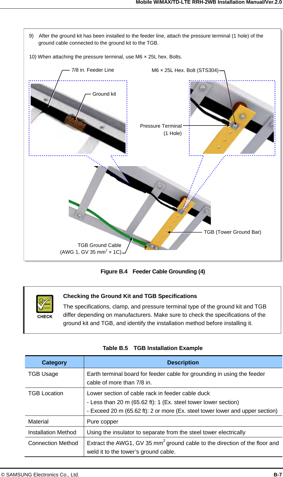
![ANNEX B. Installing Feeder Cable B-6 © SAMSUNG Electronics Co., Ltd. Figure B.3 Feeder Cable Grounding (3) 200 mm (7.87 in.) Heating GunHeat Shrink Tube 42 mm (1.65 in.) Heat Shrink Tube42 mm (1.65 in.)7) Align the 42 mm (1.65 in.) heat shrink tube [jelly type, 200 mm (7.87 in.)] inserted when installing the feeder line into the fixing part of the ground kit. 8) Shrink the heat shrink tube[jelly type, 200 mm (7.87 in.)] by heating gun. 7 8](https://usermanual.wiki/Samsung-Electronics-Co/SLS-BD104Q1.User-Manual/User-Guide-1883664-Page-104.png)
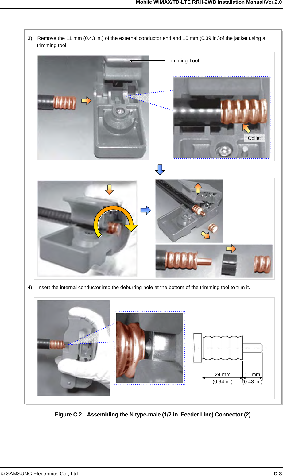
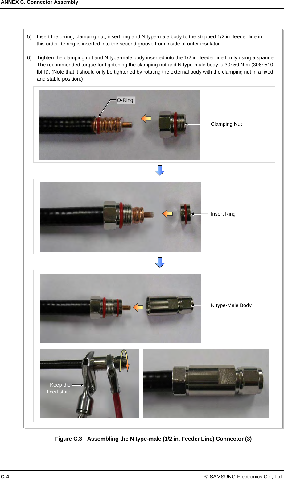
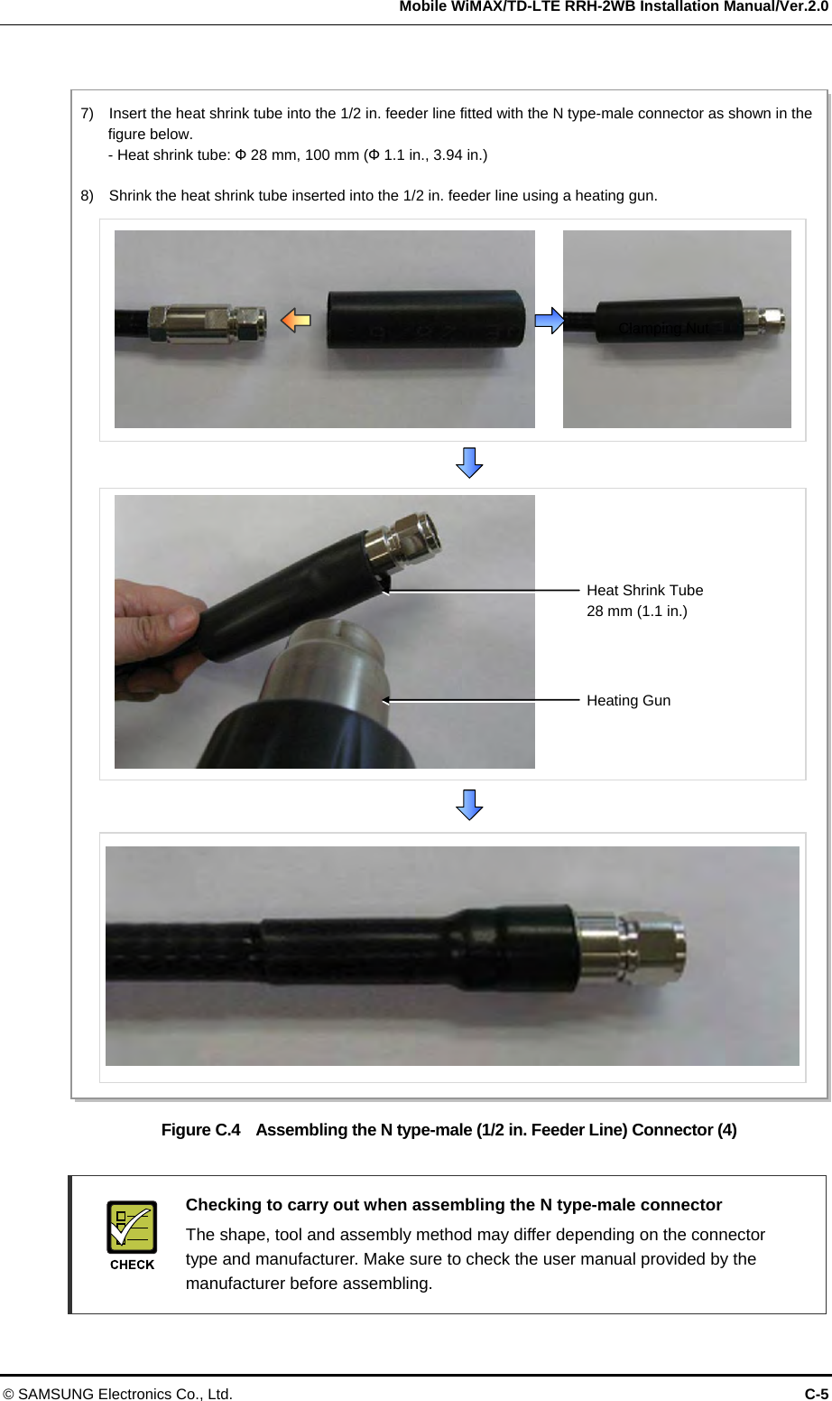
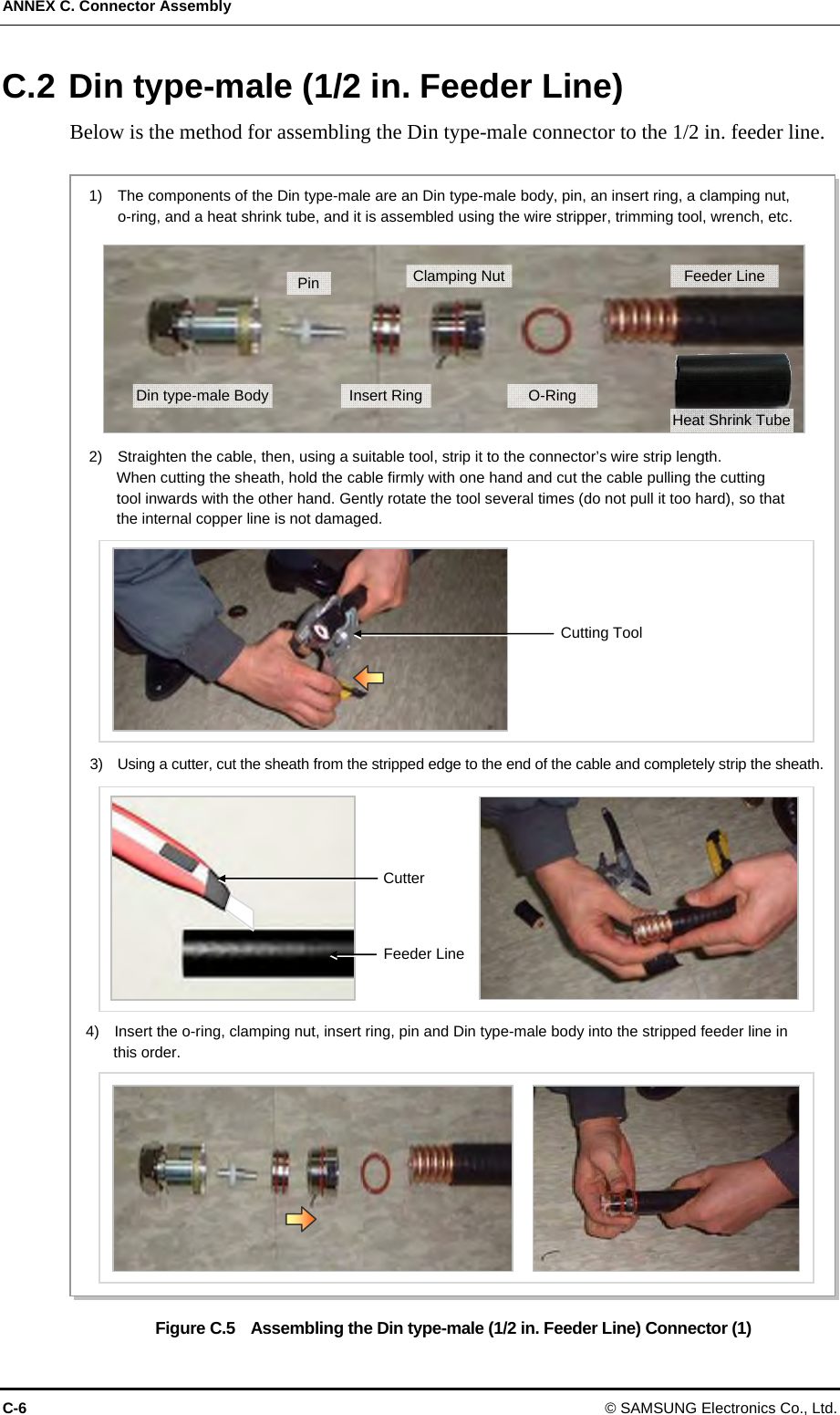
![ANNEX C. Connector Assembly C-2 © SAMSUNG Electronics Co., Ltd. Figure C.1 Assembling the N type-male (1/2 in. Feeder Line) Connector (1) 1) The components of the N type-male are an N type-male body, an insert ring, a clamping nut, O-ring, and a heat shrink tube, and it is assembled using the wire stripper, trimming tool, spanner, etc. 2) Using a stripping tool or a knife, strip the 1/2 in. feeder line by 25 mm (0.98 in.) from the end, as shown in the figure below. Trimming Tool Heat Shrink Tube [28 mm (1.1 in.)]Insert RingN type-Male Body Clamping Nut 1/2 in. Feeder Line O-Ring 25 mm1/2 in. Feeder Line Conductor1/2 in. Feeder Line Jacket](https://usermanual.wiki/Samsung-Electronics-Co/SLS-BD104Q1.User-Manual/User-Guide-1883664-Page-110.png)
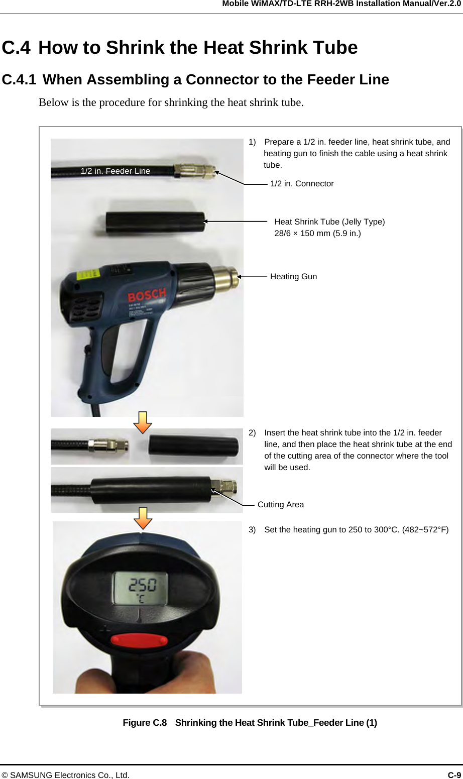
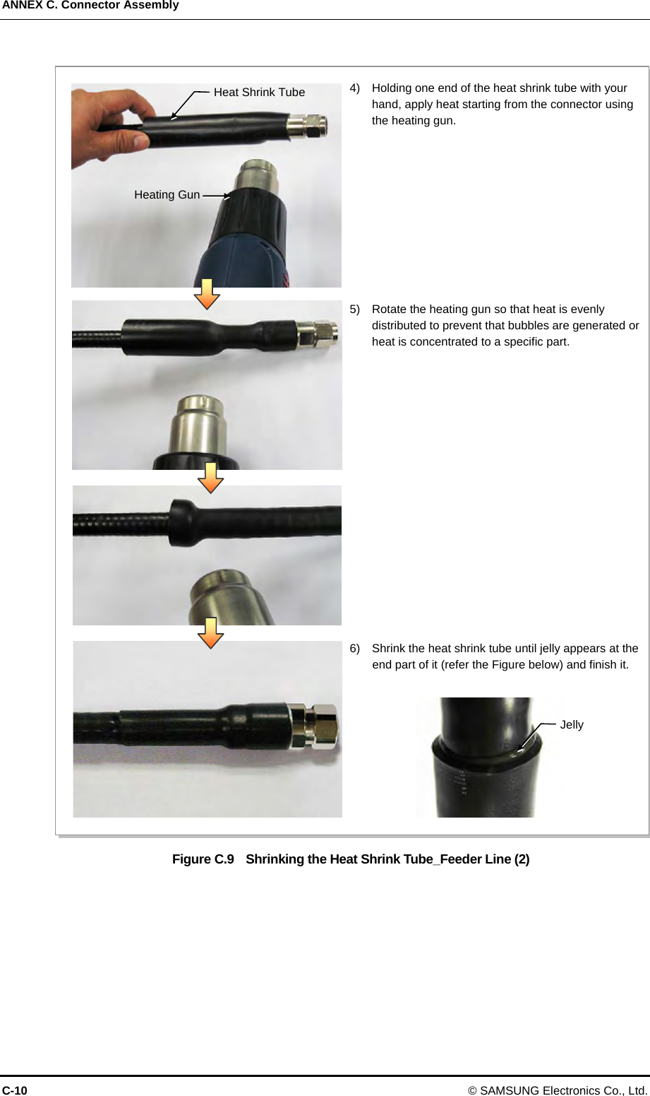
![Mobile WiMAX/TD-LTE RRH-2WB Installation Manual/Ver.2.0 © SAMSUNG Electronics Co., Ltd. C-7 Figure C.6 Assembling the Din type-male (1/2 in. Feeder Line) Connector (2) Checking to carry out when assembling the Din type-male connector The shape, tool and assembly method may differ depending on the connector type and manufacturer. Make sure to check the user manual provided by the manufacturer before assembling. Spanner (keep the fixed state) 5) Tighten firmly the clamping nut and Din type-male body inserted to the 1/2 in. feeder line using a wrench. The recommended torque for tightening the clamping nut and Din type-male body is 30~50 N.m (306~510 lbf·ft) (Note that it should only be tightened by rotating the external body with the clamping nut in a fixed and stable position.) Clamping Nut 6) Insert the heat shrink tube [28 mm/10 cm (1.10 in./3.94 in.)] to the 1/2 in. feeder line fitted with the Din type-male connector; and shrink the heat shrink tube inserted into the feeder line using a heating gun. Heating Gun Heat Shrink TubeDin type-Male Body](https://usermanual.wiki/Samsung-Electronics-Co/SLS-BD104Q1.User-Manual/User-Guide-1883664-Page-115.png)
![ANNEX C. Connector Assembly C-16 © SAMSUNG Electronics Co., Ltd. Figure C.14 Power Connector Assembly (2) 5) Insert the connector pin assembled with the power cable into the end of connector. The pin map of connector end and cable is as below. - C: -48 VDC/Black - D: Return/White Push the pin into the end and check if it does not pull off. 6) After connecting the connector end and the pin assembled with the cable, assemble the connector parts to the connector end one by one. 7) Place the heat shrink tube [38 mm (1.50 in.)] to the lead-in part of connector cable, and shrink it using the heating gun. Do not shrink the tube for too long time since the jelly might come out too much.](https://usermanual.wiki/Samsung-Electronics-Co/SLS-BD104Q1.User-Manual/User-Guide-1883664-Page-124.png)
![ANNEX D. Cleaning Optic Connector D-2 © SAMSUNG Electronics Co., Ltd. D.2 IBCTM Brand Cleaner Method that uses IBCTM Brand Cleaner is as follows: D.2.1 IBCTM Brand Type Cleaner (P/N 9393) Method that uses IBCTM Brand Cleaner for LC-LC and MU connector is as follows: Figure D.1 Optic Connector Cleaner (IBCTM Brand Type Cleaner: P/N 9393) Outer Shell[Optic Connector Cleaner Configuration]Nozzle Guide CapLock Button (for Extend Nozzle)[Nozzle Extension] [In Case of LC type Connector (Plug)] Guide CapGuide Cap Cover [In Case of LC type Connector (Jack)] Guide CapLock Button (for Extend Nozzle)](https://usermanual.wiki/Samsung-Electronics-Co/SLS-BD104Q1.User-Manual/User-Guide-1883664-Page-126.png)
![Mobile WiMAX/TD-LTE RRH-2WB Installation Manual/Ver.2.0 © SAMSUNG Electronics Co., Ltd. D-3 Optic Module Cleaning (LC Type Jack) Figure D.2 Optic Module Cleaning (LC Type Jack) Guide Cap 1) To clean the optic module, remove the guide cap from the cleaner (P/N: 9393). 2) Insert a cleaner guide cap to every core of the optic module. Clean it by pushing the outer shell toward the nozzle until you hear the sound of the detergent being sprayed. (Repeat once or twice.) Outer Shell Nozzle Nozzle Outer Shell Optic Module[IBC Brand Cleaner: P/N 9393]](https://usermanual.wiki/Samsung-Electronics-Co/SLS-BD104Q1.User-Manual/User-Guide-1883664-Page-127.png)
![ANNEX D. Cleaning Optic Connector D-4 © SAMSUNG Electronics Co., Ltd. Optic Cable Connector Cleaning (LC Type Plug) Figure D.3 Optic Cable Connector Cleaning (LC Type Plug) Guide CapGuide Cap Cover 1) To clean the optic cable connector, open the guide cap cover from the cleaner (P/N: 9393). 2) Insert a cleaner guide cap to every core of the optic cable connector. Clean it by pushing the outer shell toward the nozzle until you hear the sound of the detergent being sprayed. (Repeat once or twice.) Outer ShellNozzle Guide Cap Nozzle Outer Shell LC Type Connector[IBC Brand Cleaner: P/N 9393]](https://usermanual.wiki/Samsung-Electronics-Co/SLS-BD104Q1.User-Manual/User-Guide-1883664-Page-128.png)
![Mobile WiMAX/TD-LTE RRH-2WB Installation Manual/Ver.2.0 © SAMSUNG Electronics Co., Ltd. D-5 D.2.2 IBCTM Brand Type Cleaner (P/N 12910) Method that uses IBCTM Brand Cleaner for ODC connector is as follows: Figure D.4 Optic Connector Cleaner (IBCTM Brand Type Cleaner: P/N 12910) Outer Shell [Optic Connector Cleaner Configuration]Nozzle Guide CapLock Button (for Extend Nozzle)[Nozzle Extension] [In Case of LC type Connector (Plug)] Guide CapGuide Cap Cover [In Case of LC type Connector (Jack)] Guide CapLock Button (for Extend Nozzle)](https://usermanual.wiki/Samsung-Electronics-Co/SLS-BD104Q1.User-Manual/User-Guide-1883664-Page-129.png)
![ANNEX D. Cleaning Optic Connector D-6 © SAMSUNG Electronics Co., Ltd. Optic Port Cleaning (ODC, PT/LC Jack) Figure D.5 Optic Port Cleaning (ODC, PT/LC Jack) [Optic Port of System: ODC-4]1) To clean the optic port of system, remove the guide cap from the cleaner. Guide Cap2) Insert a cleaner guide cap to every core hole of the system’s optic port. Clean it by pushing the outer shell toward the nozzle until you hear the sound of the detergent being sprayed. (Repeat once or twice.) Outer Shell Nozzle Core Guide Cap Cover[Optic Port of System: PT/LC] Core](https://usermanual.wiki/Samsung-Electronics-Co/SLS-BD104Q1.User-Manual/User-Guide-1883664-Page-130.png)
![Mobile WiMAX/TD-LTE RRH-2WB Installation Manual/Ver.2.0 © SAMSUNG Electronics Co., Ltd. D-7 Optic Cable Connector Cleaning (ODC Type Plug) Figure D.6 Optic Cable Connector Cleaning (ODC Type Plug) Guide Cap 1) To clean the ODC connector of cable, remove the guide cap from the cleaner (P/N: 12910). 2) Insert a cleaner guide cap to every core hole of the ODC connector. Clean it by pushing the outer shell toward the nozzle until you hear the sound of the detergent being sprayed. (Repeat once or twice.) Outer Shell Nozzle Outer Shell Nozzle ODC Connector[IBC Brand Cleaner: P/N 12910]](https://usermanual.wiki/Samsung-Electronics-Co/SLS-BD104Q1.User-Manual/User-Guide-1883664-Page-131.png)
![ANNEX D. Cleaning Optic Connector D-8 © SAMSUNG Electronics Co., Ltd. Optic Cable Connector Cleaning (PT/LC Type Plug) Figure D.7 Optic Cable Connector Cleaning (PT/LC Type Plug) Guide Cap 1) To clean the PT/LC connector of cable, remove the guide cap from the cleaner (P/N: 12910). 2) Insert a cleaner guide cap to every core hole of the the PT/LC connector. Clean it by pushing the outer shell toward the nozzle until you hear the sound of the detergent being sprayed. (Repeat once or twice.)Outer Shell Nozzle Outer Shell Nozzle PT/LC Connector[IBC Brand Cleaner: P/N 12910]](https://usermanual.wiki/Samsung-Electronics-Co/SLS-BD104Q1.User-Manual/User-Guide-1883664-Page-132.png)
![Mobile WiMAX/TD-LTE RRH-2WB Installation Manual/Ver.2.0 © SAMSUNG Electronics Co., Ltd. D-9 Measuring the Optical Output and Connecting the Optic Connector Figure D.8 Measuring the Optical Output and Connecting the Optic Connector [Optic Powermeter] 1) Check the optical output again using an optic power meter. 2) If the optical output measurement result meets the reference value, clean the connector again and connect it. If the measurement result does not meet the reference value, discard the cable, replace it with a new cable, and then clean the new one and connect it to the system. [LC/PC Plug] [PT/LC Plug] [ODC Plug] [Harting Plug]](https://usermanual.wiki/Samsung-Electronics-Co/SLS-BD104Q1.User-Manual/User-Guide-1883664-Page-133.png)
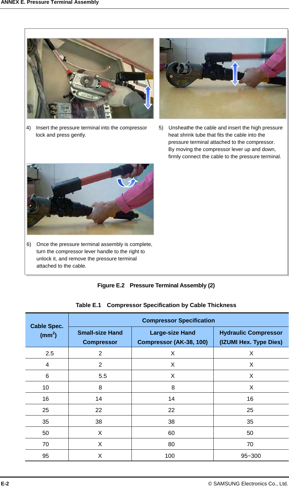
![Mobile WiMAX/TD-LTE RRH-2WB Installation Manual © SAMSUNG Electronics Co., Ltd. E-1 ANNEX E. Pressure Terminal Assembly Method that assembles the pressure terminal by using the crimp-type compressor is as follows: Figure E.1 Pressure Terminal Assembly (1) [Ring Type Dies] [Hex. Type Dies] [Hydraulic Pressure Terminal Compressor] 1) Select the appropriate compressor and dies for the cable specification and pressure type. 2) Attach the cable and dies satisfying the pressure terminal specification to the lower section of the compressor terminal. 3) Attach the cable and dies satisfying the pressure terminal specification to the upper section of the compressor terminal.](https://usermanual.wiki/Samsung-Electronics-Co/SLS-BD104Q1.User-Manual/User-Guide-1883664-Page-135.png)