Samsung Electronics Co SLS-BR02BQ RRU(Remote Radio Unit) User Manual Smart MBS RRH B8 Installation Manual Ver 3 2 Sprint ENx
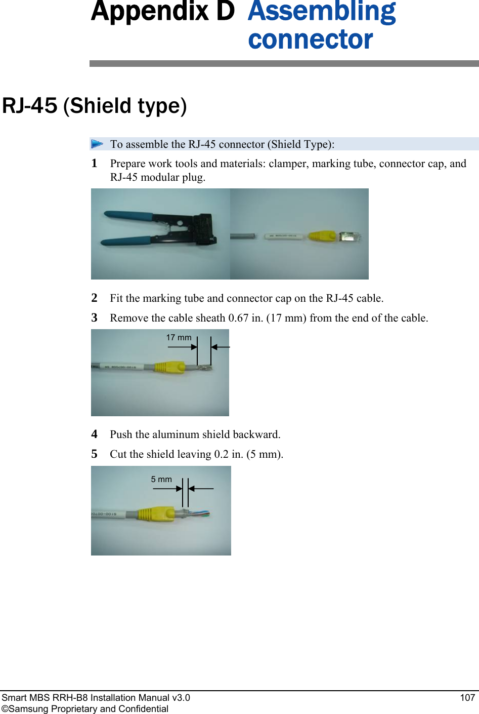
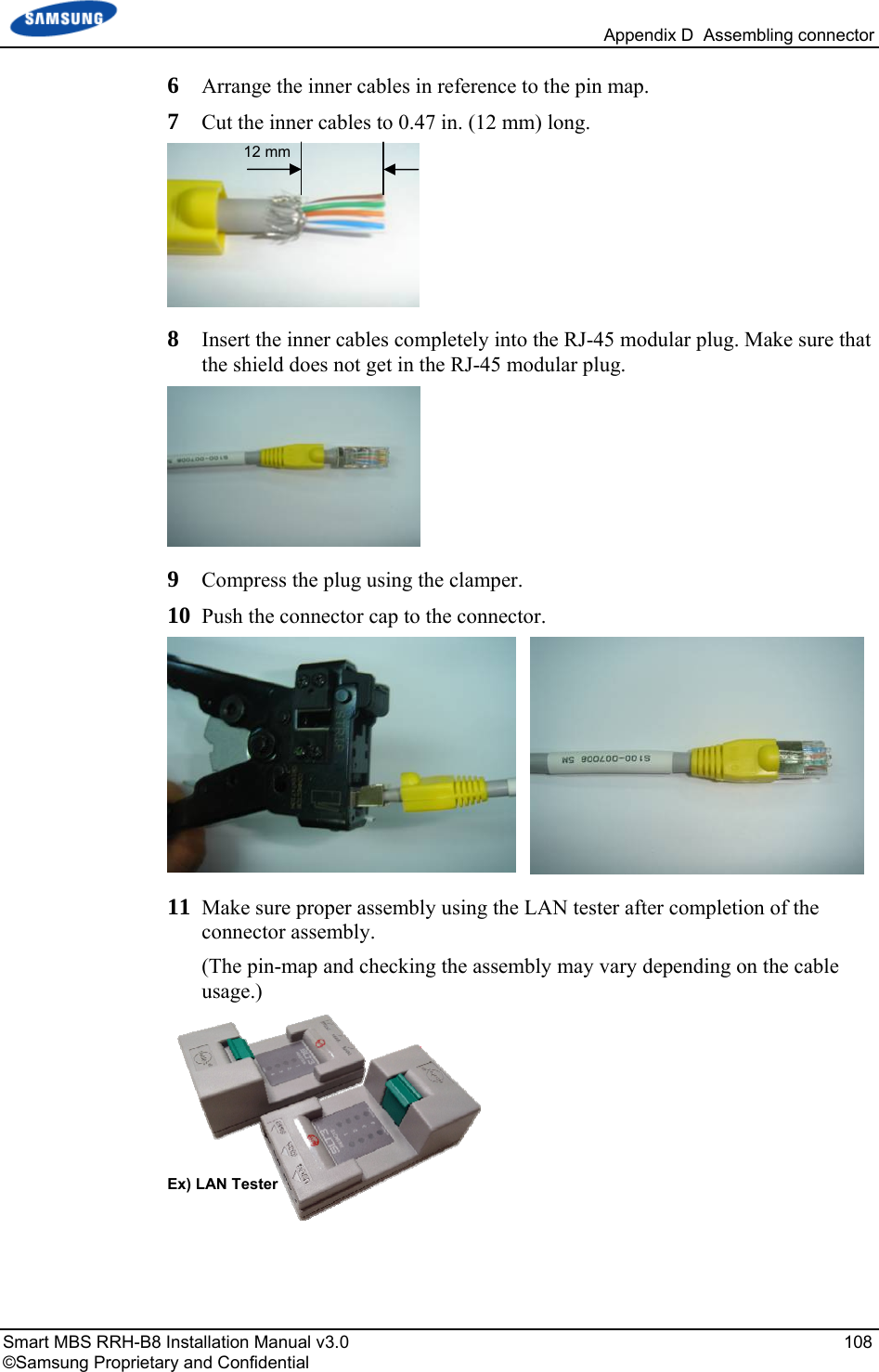
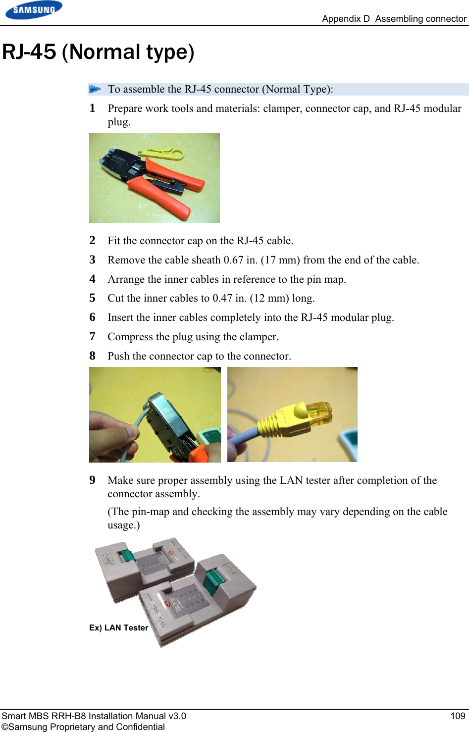
Samsung Electronics Co Ltd RRU(Remote Radio Unit) Smart MBS RRH B8 Installation Manual Ver 3 2 Sprint ENx
Contents
- 1. Users Manual
- 2. User Manual_20151112_v1 - SLS-BR02BQ_User manual_rev02
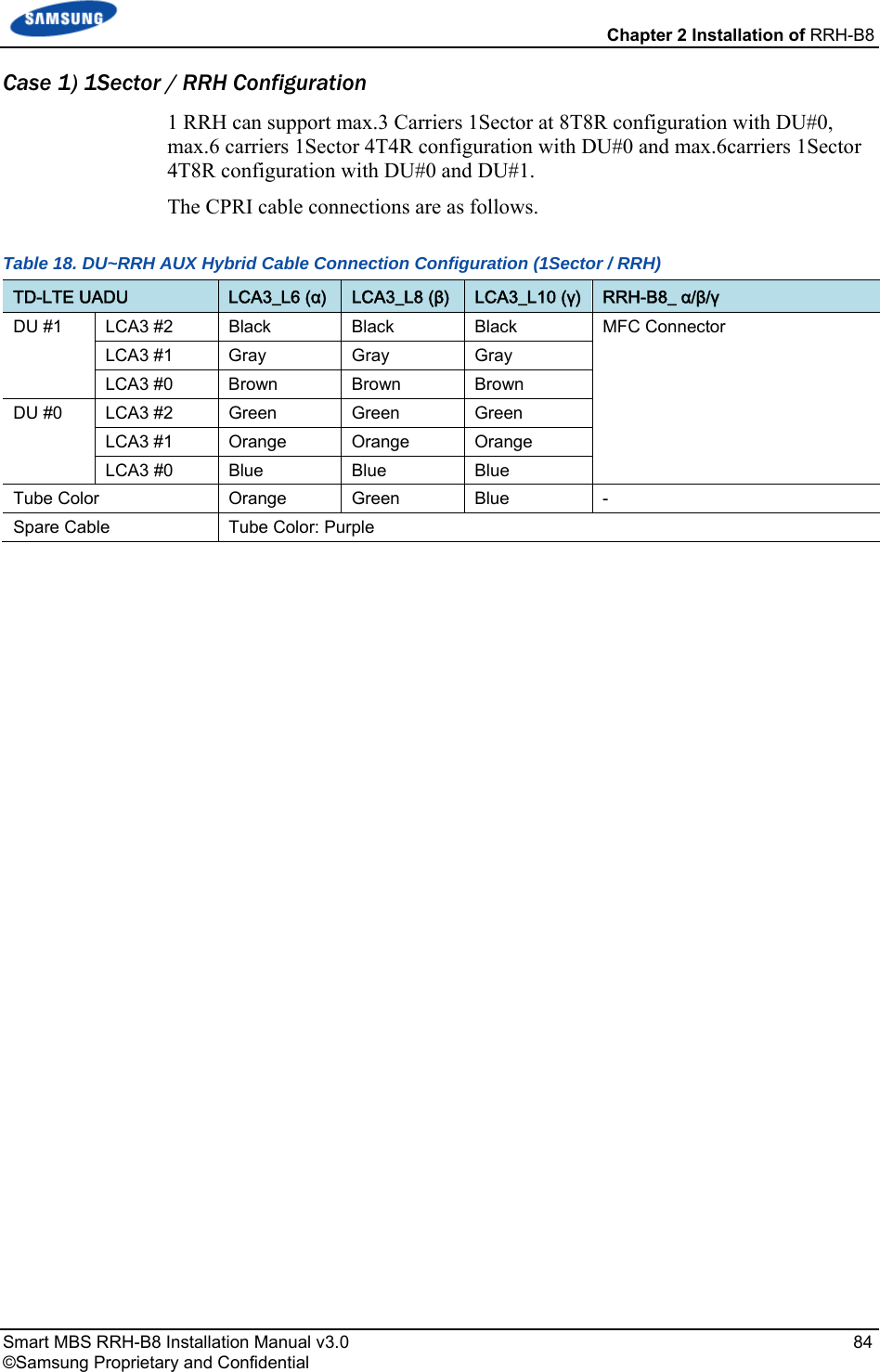
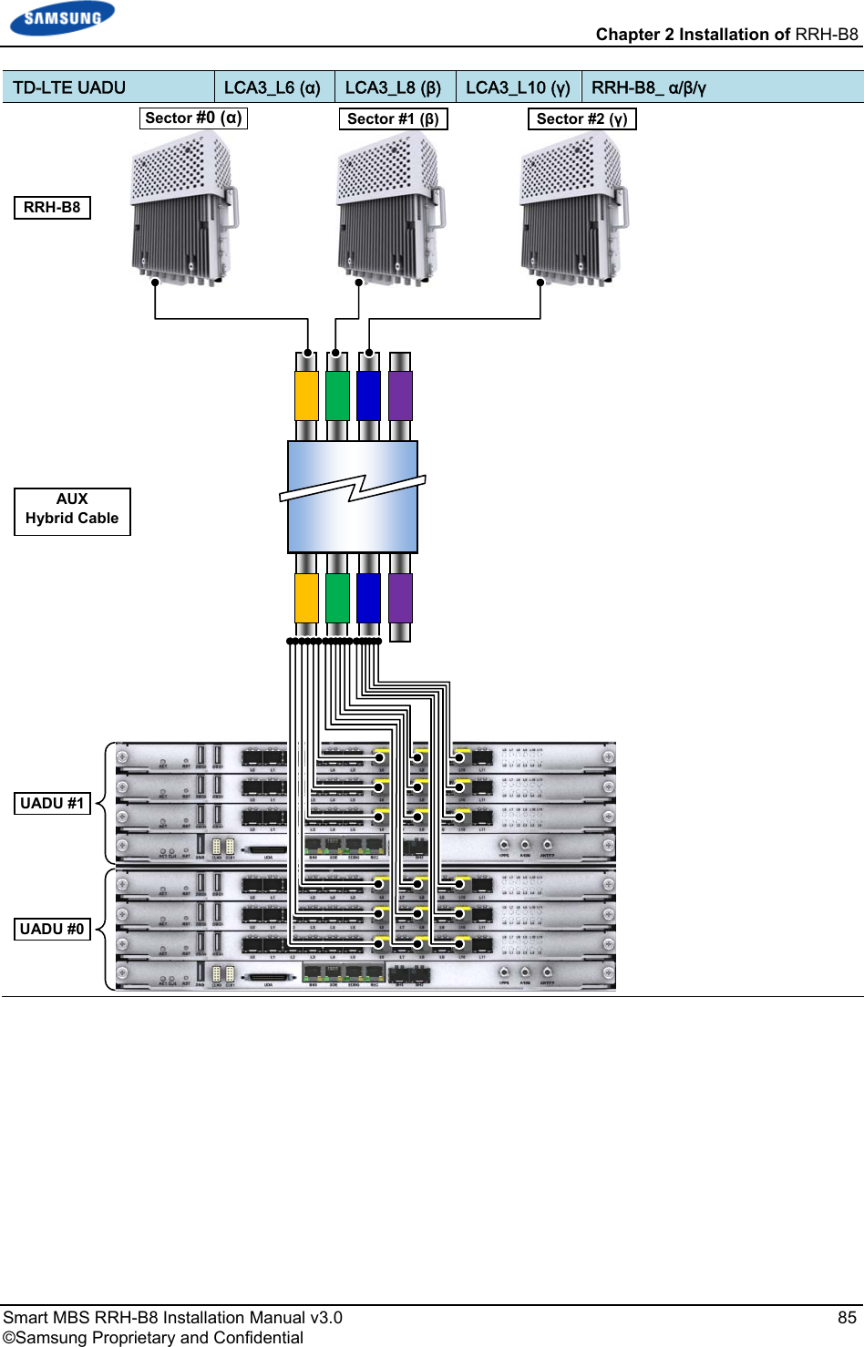
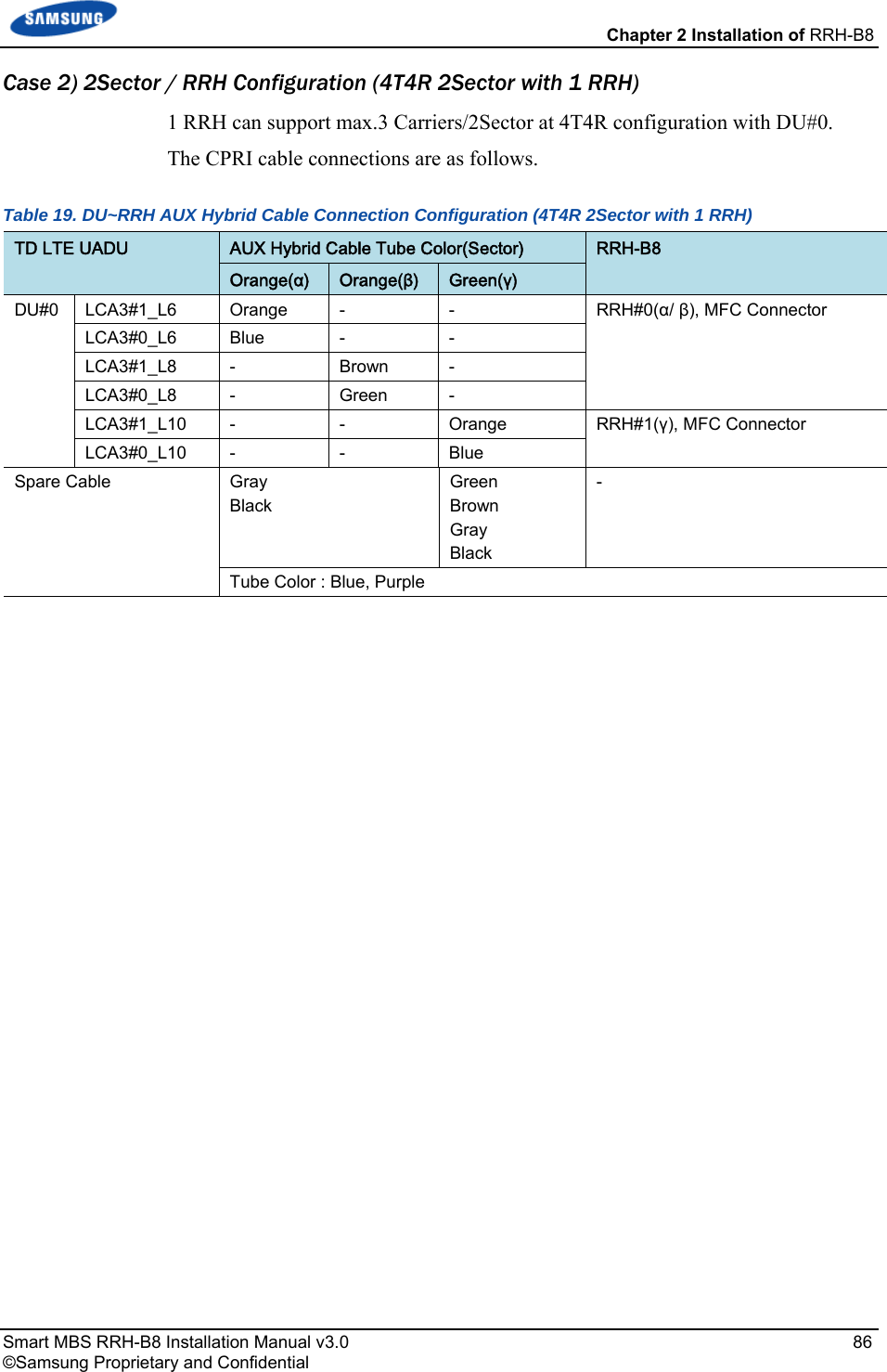
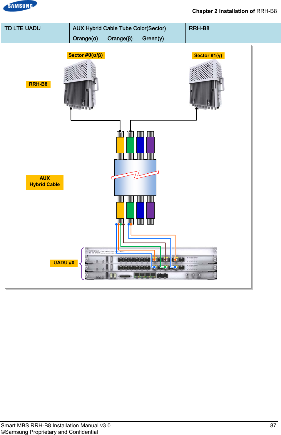
User Manual_20151112_v1 - SLS-BR02BQ_User manual_rev02
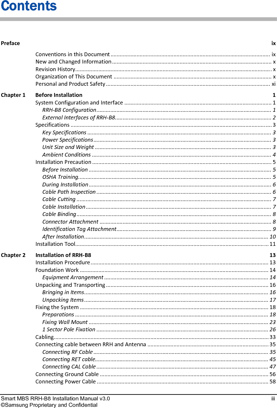
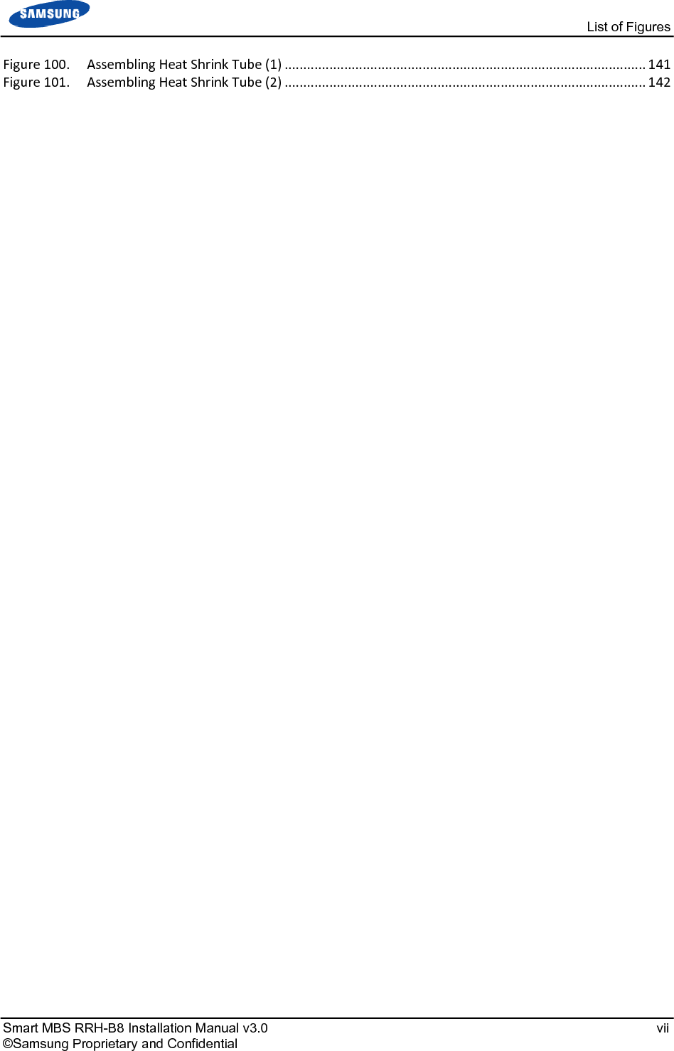
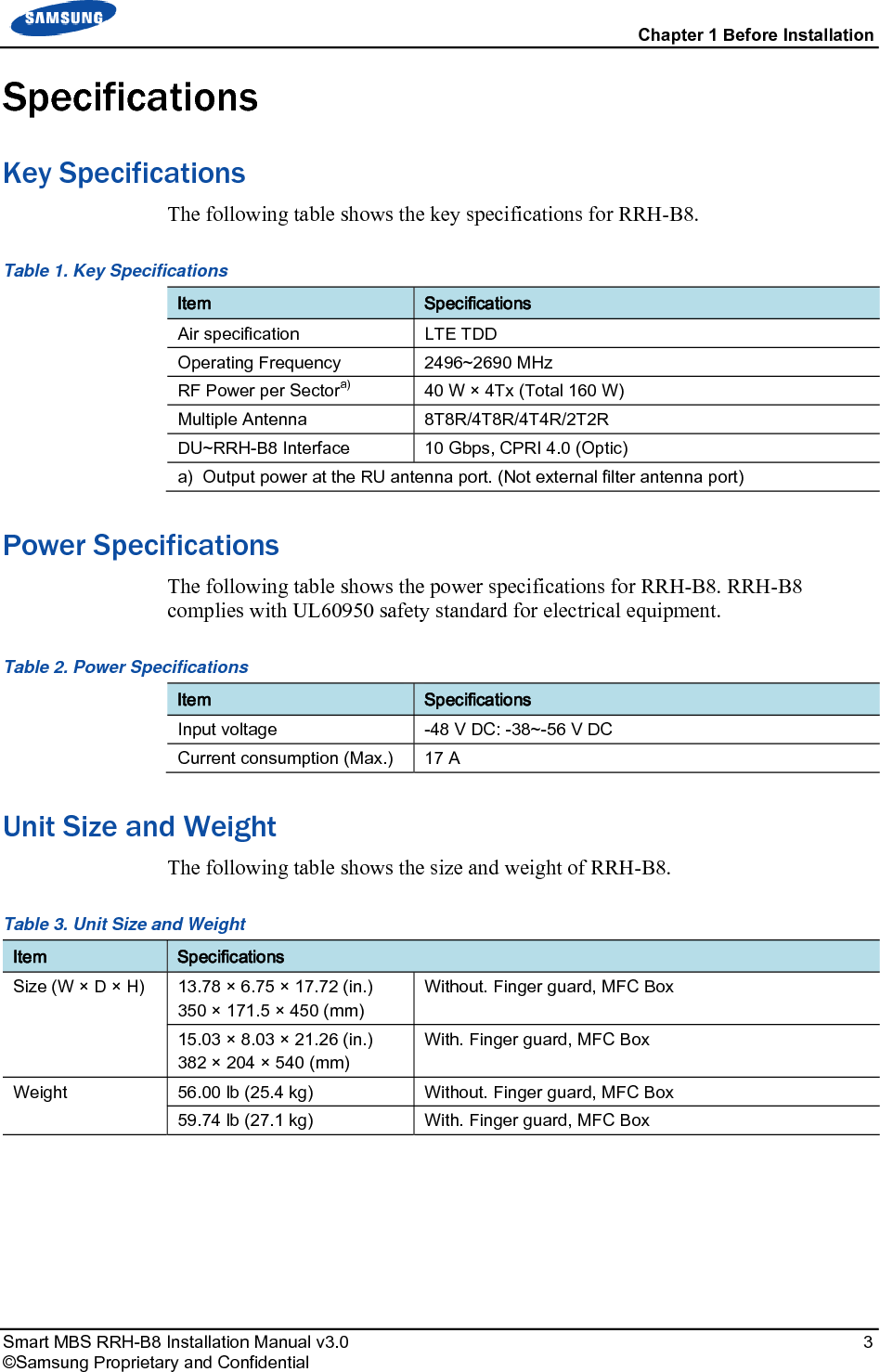
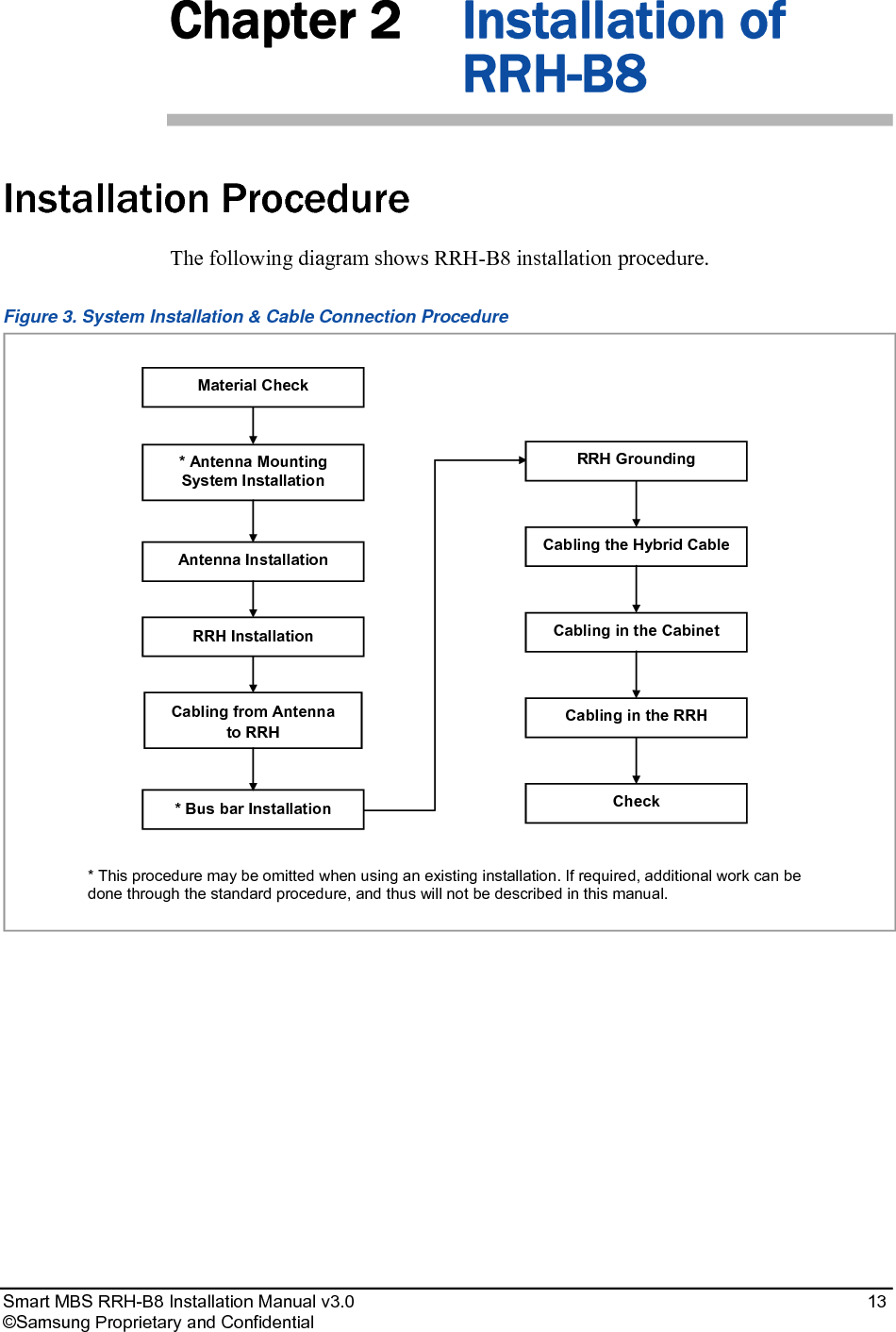
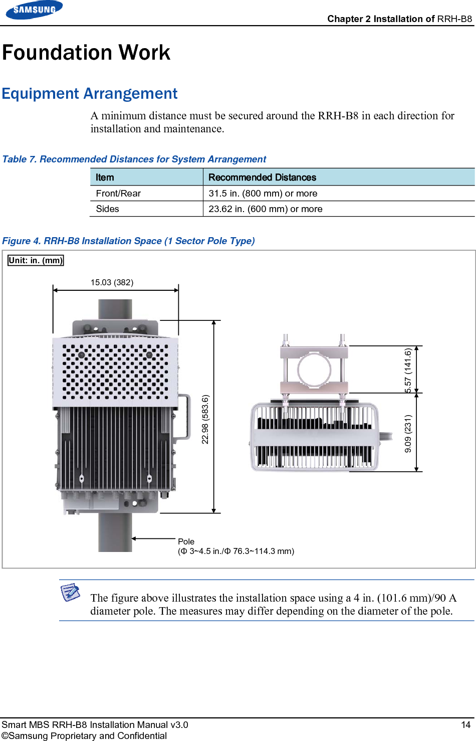
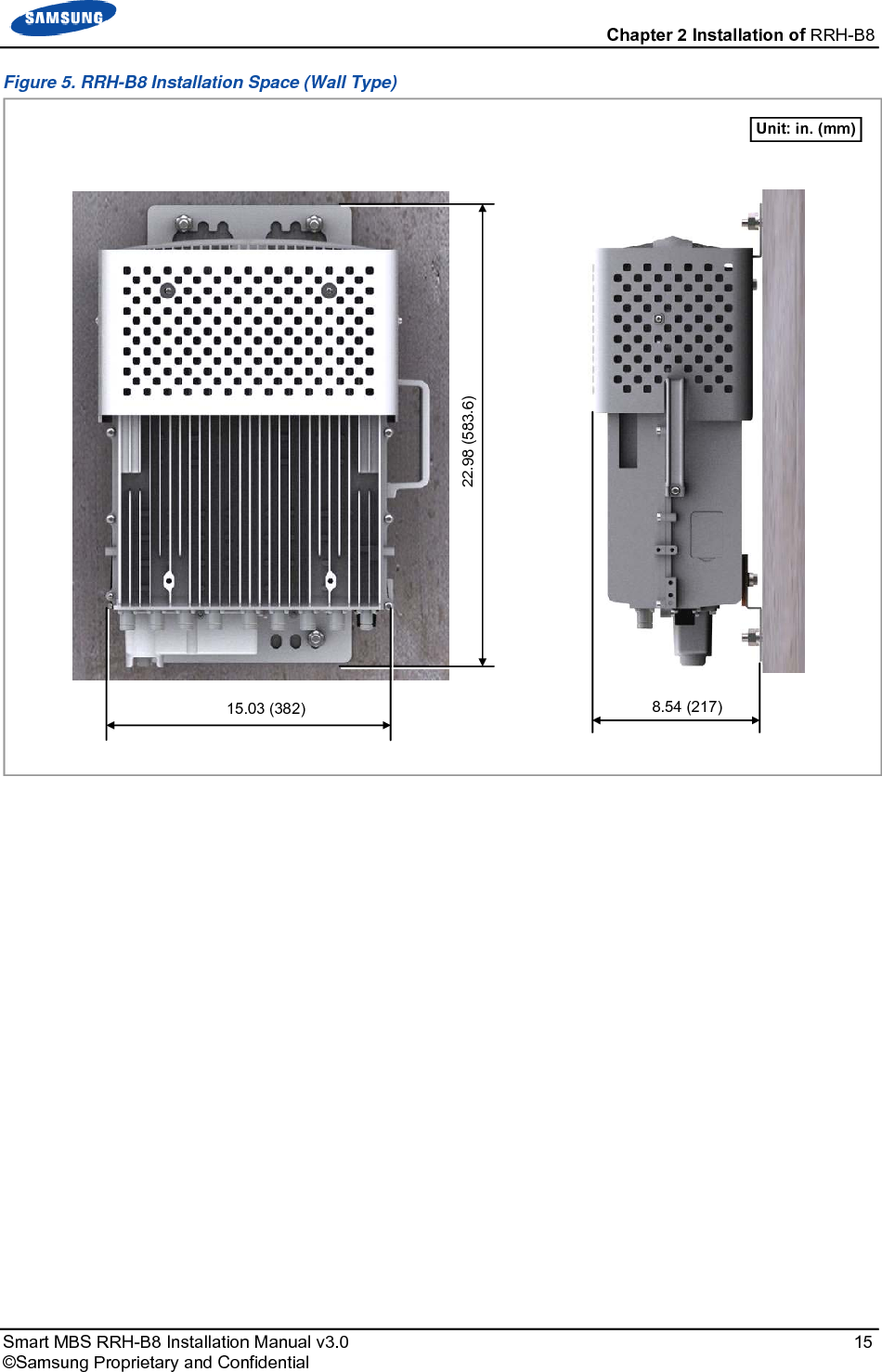
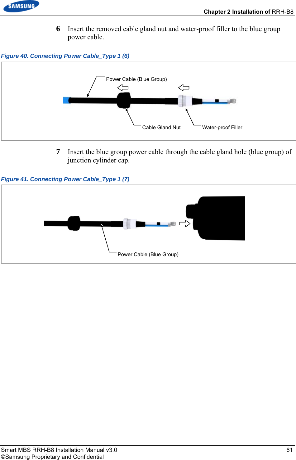
![Smart MBS RRH-B8 Installation Manual v3.0 1 ©Samsung Proprietary and Confidential Chapter 1 Before Installation System Configuration and Interface RRH-B8 Configuration The following shows the configuration of RRH-B8. Figure 1. RRH-B8 Configuration [Top View] [Front View][Bottom View][Right View] [Left View] [Rear View] 21.1 (536) 9.45 (240) 15.03 (382) Unit:in. (mm)](https://usermanual.wiki/Samsung-Electronics-Co/SLS-BR02BQ.User-Manual-20151112-v1-SLS-BR02BQ-User-manual-rev02/User-Guide-2822460-Page-15.png)
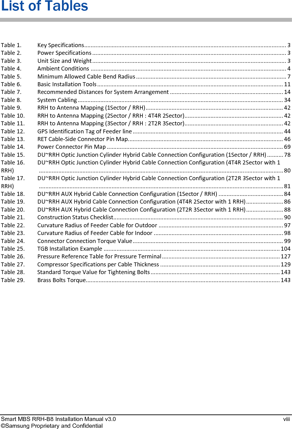
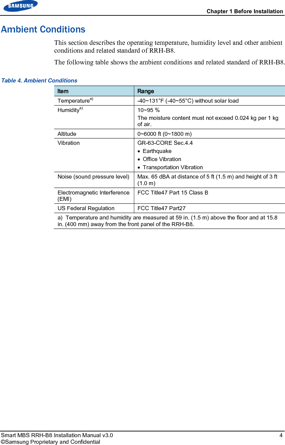
![Chapter 1 Before Installation Smart MBS RRH-B8 Installation Manual v3.0 2 ©Samsung Proprietary and Confidential External Interfaces of RRH-B8 The following shows the external interfaces of RRH-B8. Figure 2. External Interfaces of RRH-B8 [Bottom View] PWR [-48 V] Ground ANT_0 ANT_1 ANT_2 ANT_3 ANT_4 ANT_5 ANT_6 ANT_7 CAL RET CPRI (MFC)](https://usermanual.wiki/Samsung-Electronics-Co/SLS-BR02BQ.User-Manual-20151112-v1-SLS-BR02BQ-User-manual-rev02/User-Guide-2822460-Page-16.png)


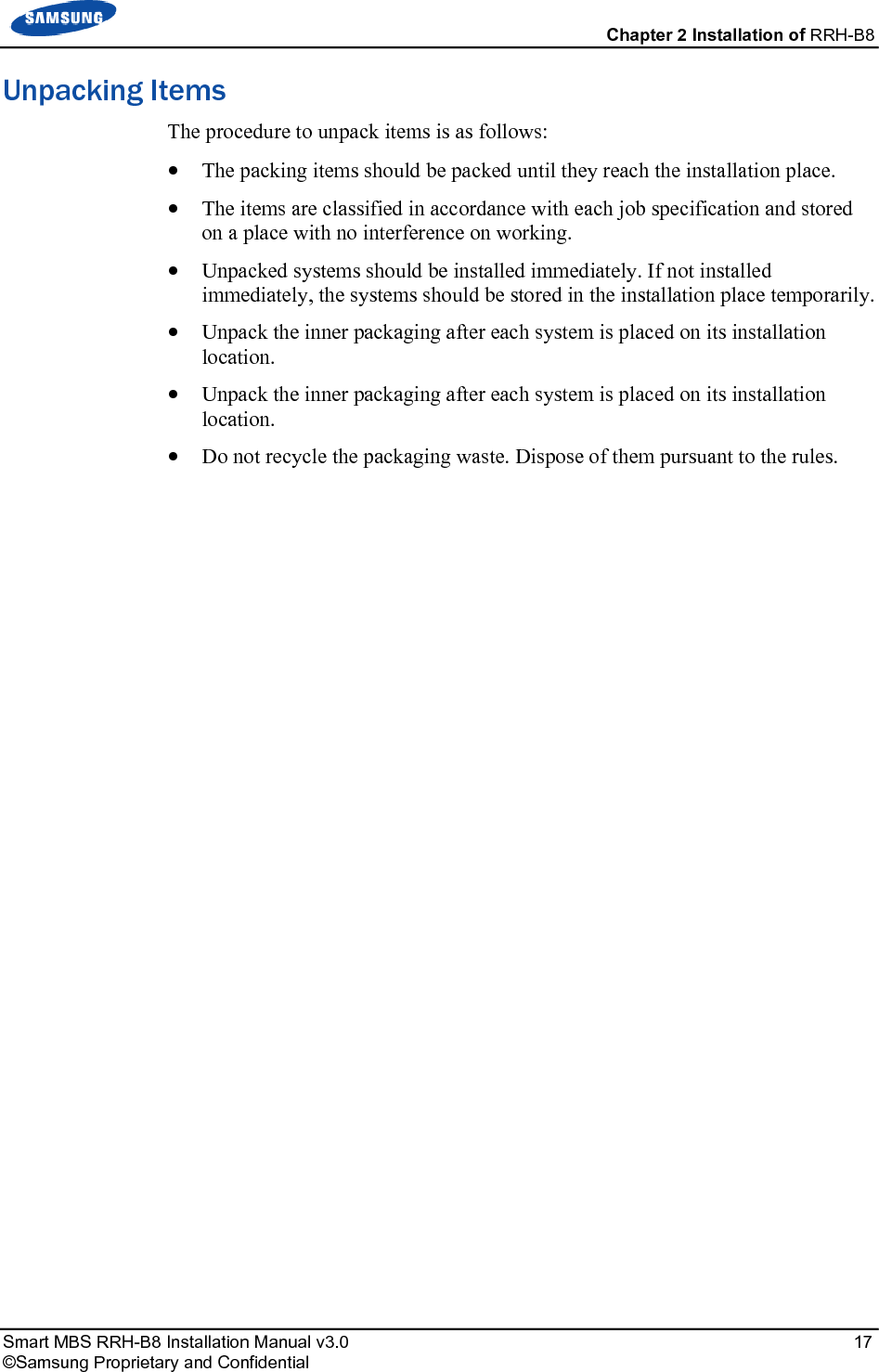
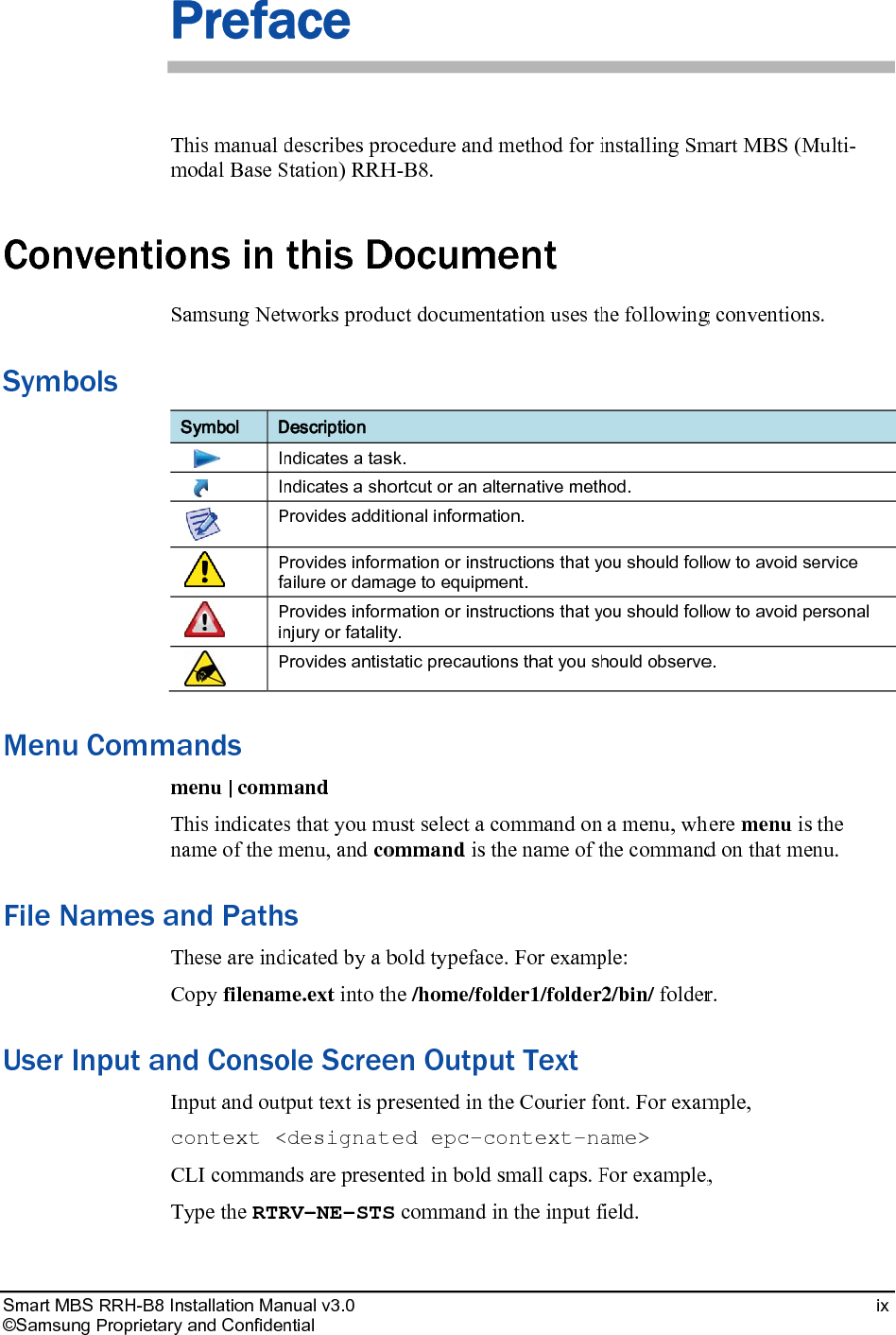
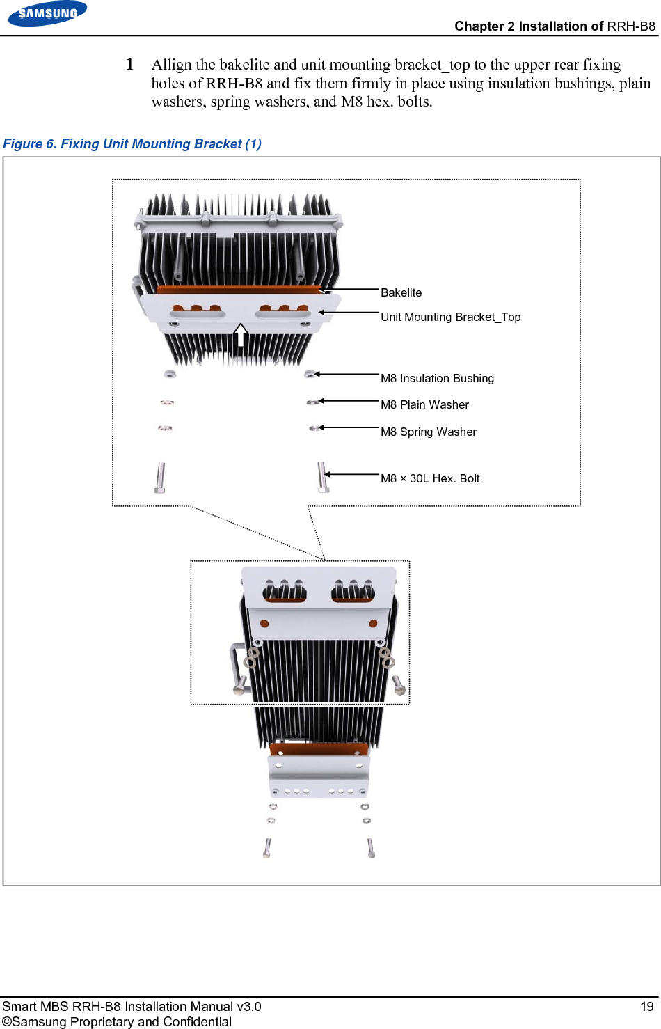
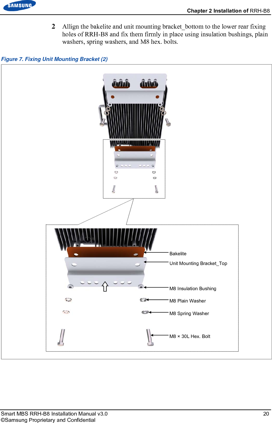
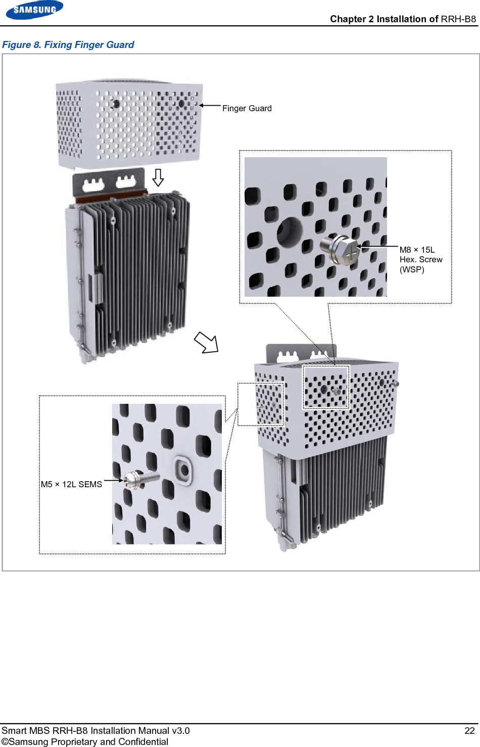
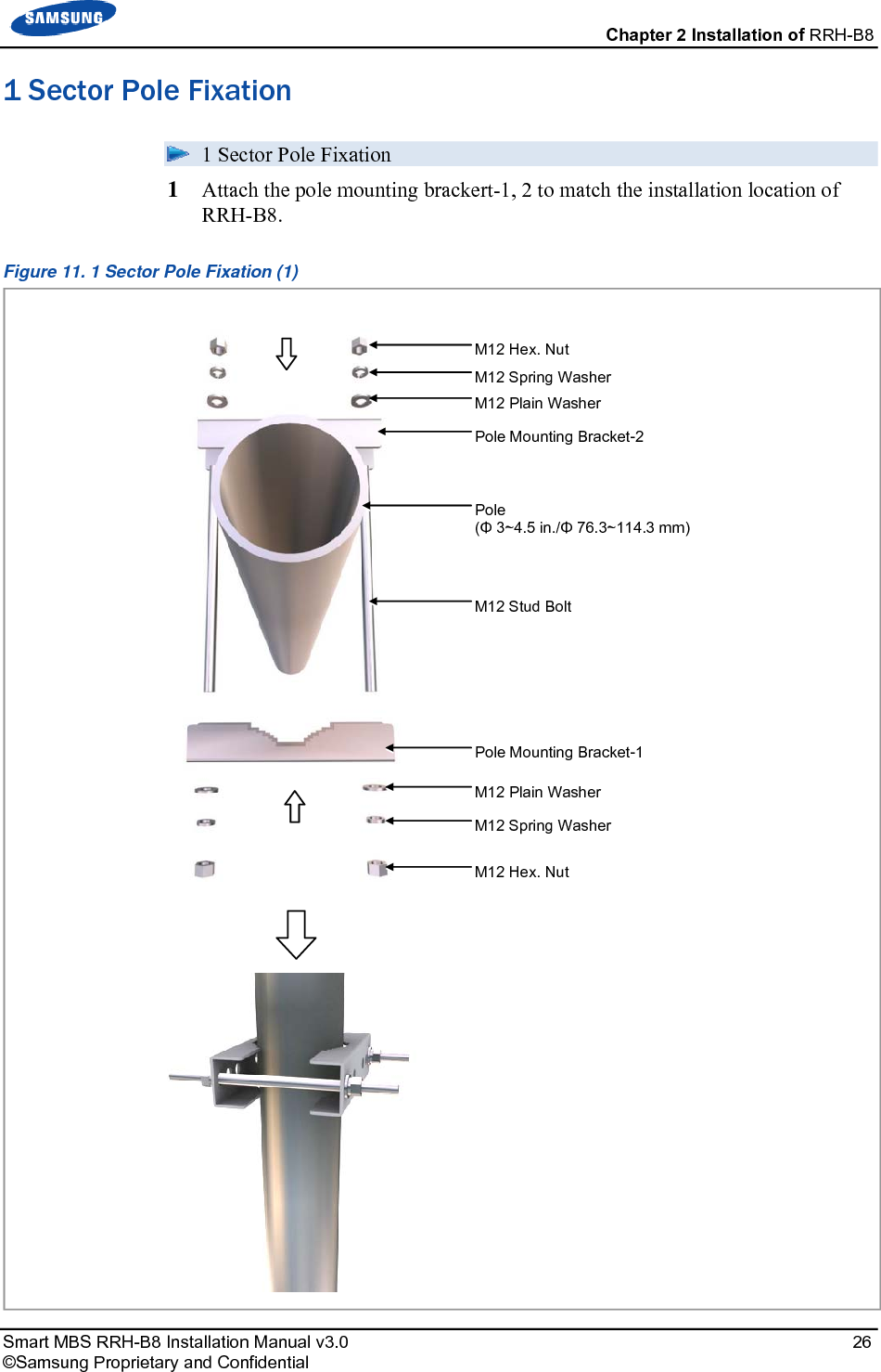
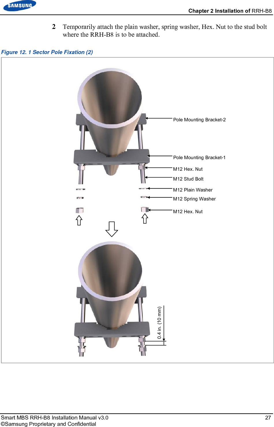
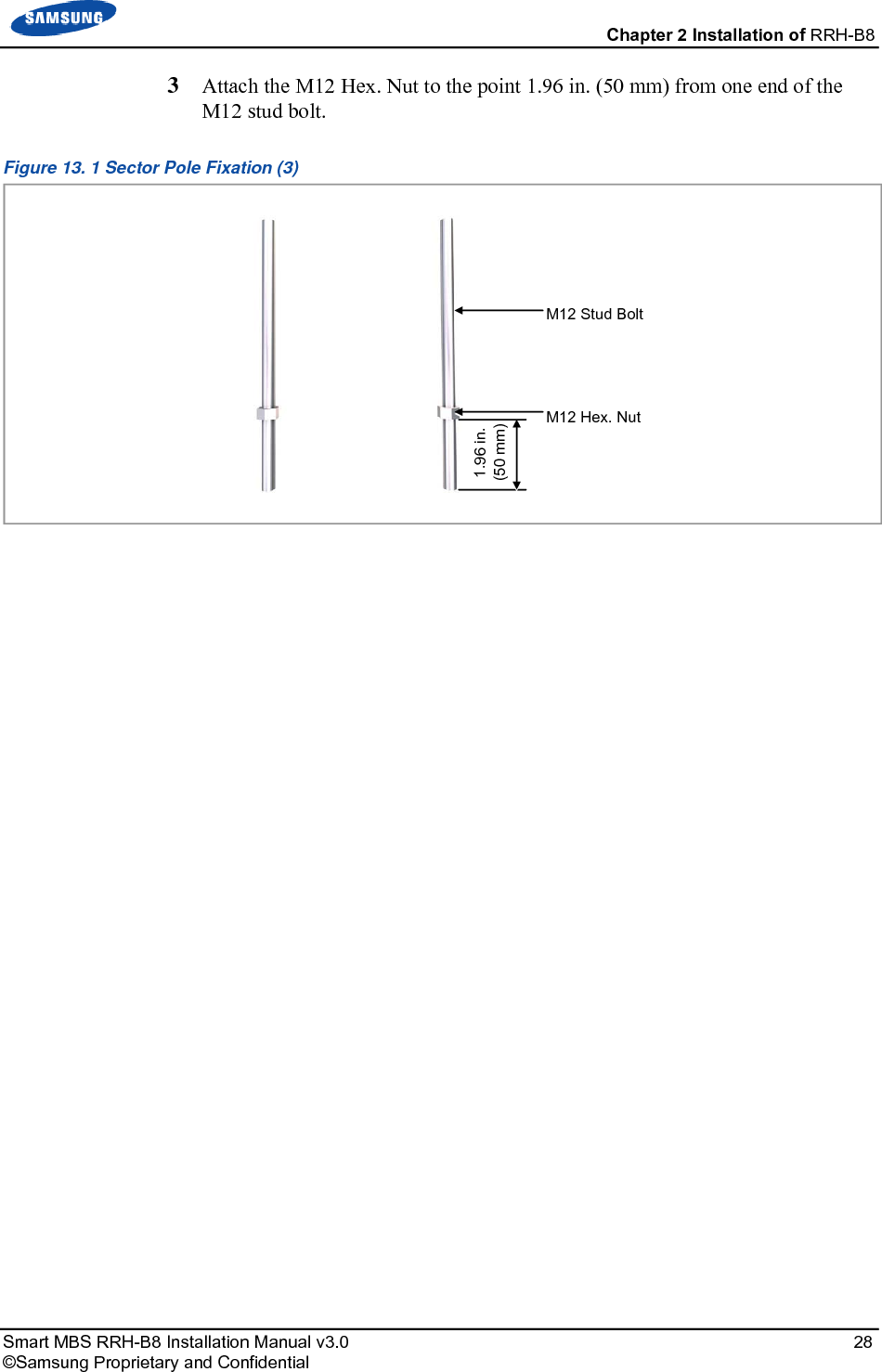
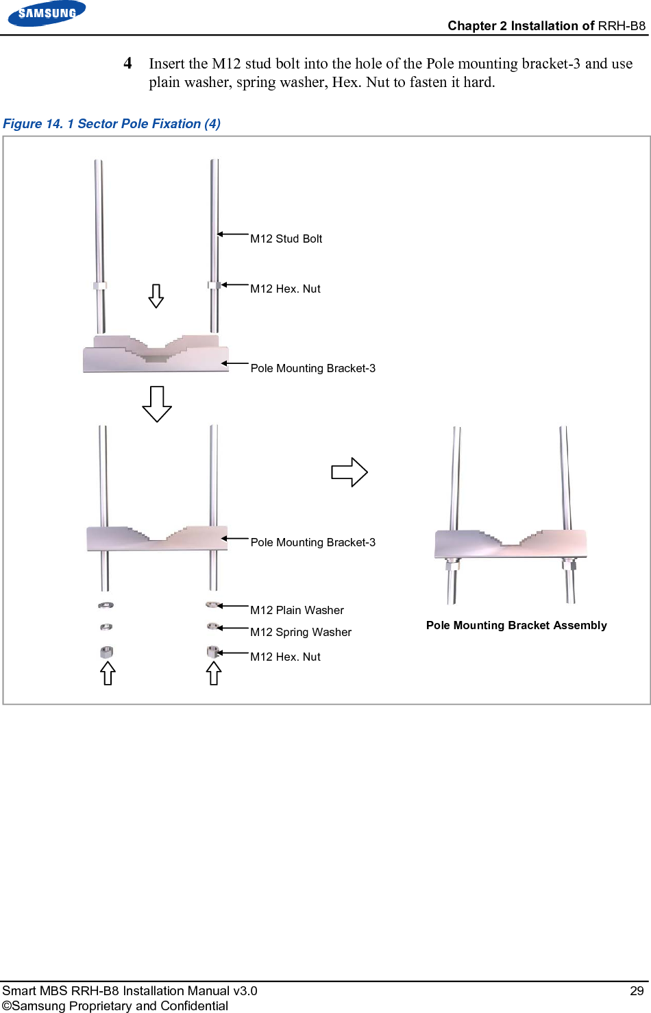
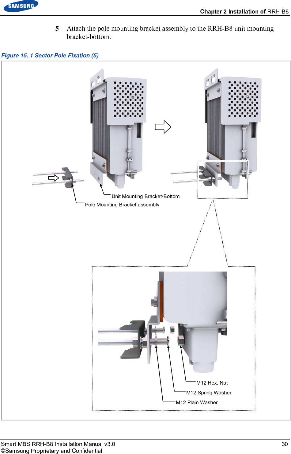
![Chapter 2 Installation of RRH-B8 Smart MBS RRH-B8 Installation Manual v3.0 18 ©Samsung Proprietary and Confidential Fixing the System Preparations For the system fixation, assemble the unit mounting brackets and finger guard first on the ground. Fixing Unit Mounting Bracket Fixing Unit Mounting Bracket There are two types of unit mounting brackets, for top and bottom. [Unit Mounting Bracket_Top] [Unit Mounting Bracket_Bottom] Unit Mounting Bracket_Top Unit Mounting Bracket_Bottom](https://usermanual.wiki/Samsung-Electronics-Co/SLS-BR02BQ.User-Manual-20151112-v1-SLS-BR02BQ-User-manual-rev02/User-Guide-2822460-Page-32.png)
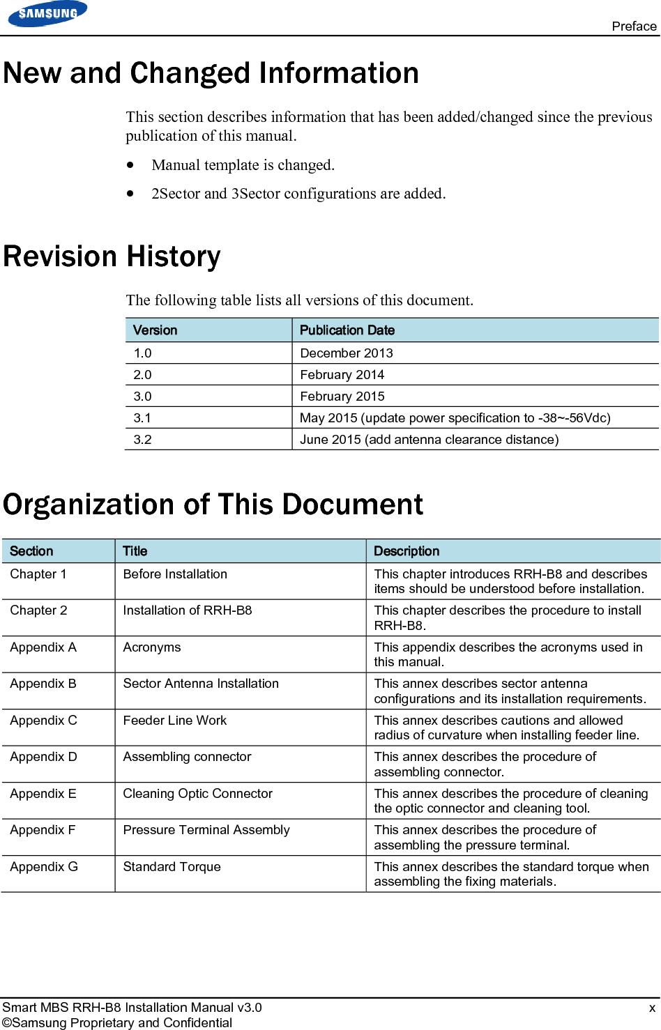
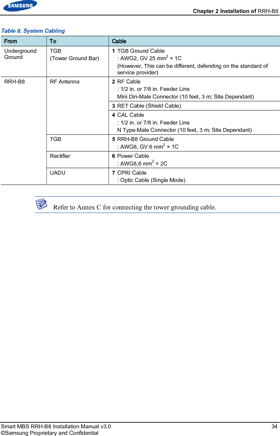
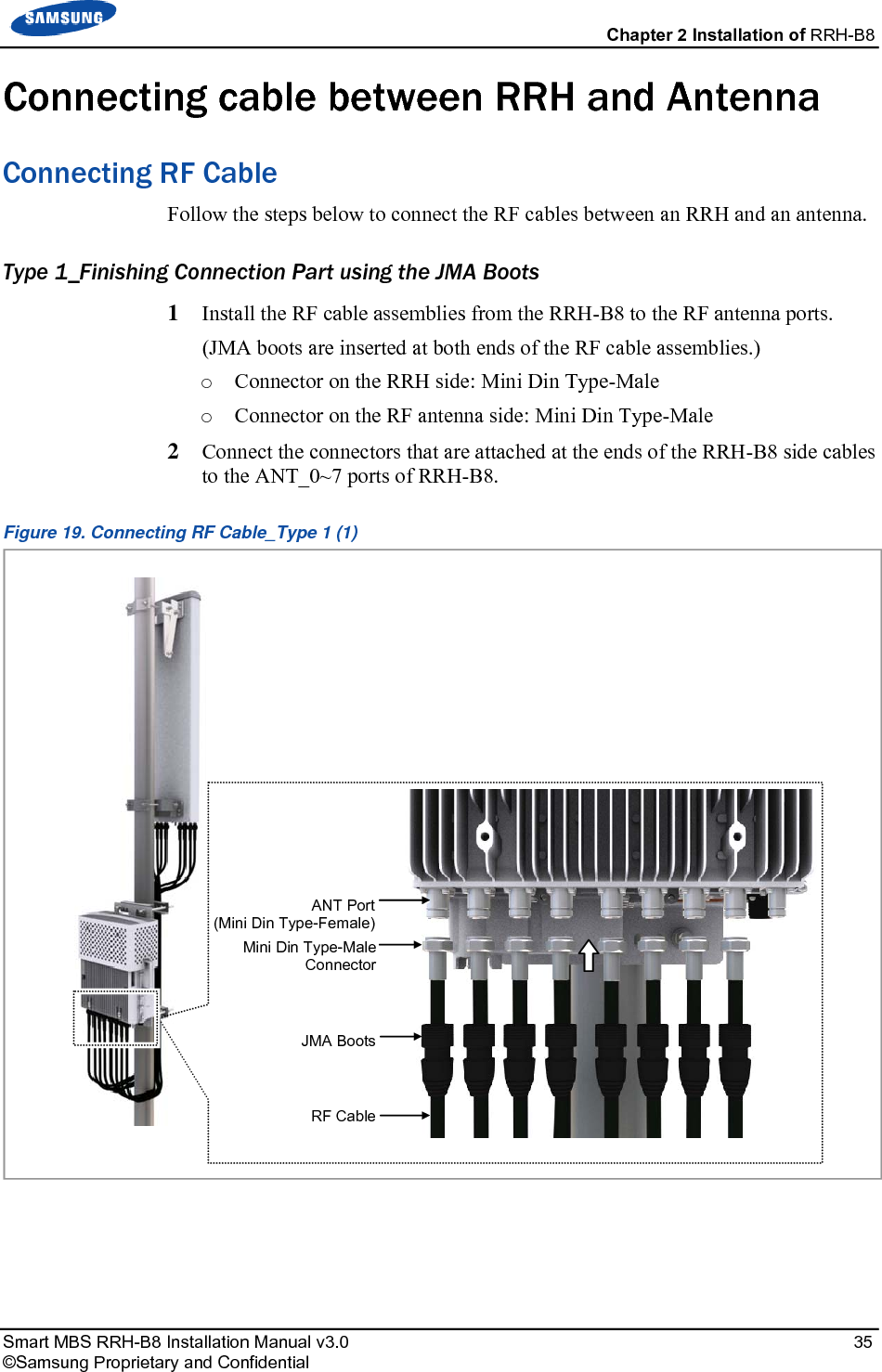
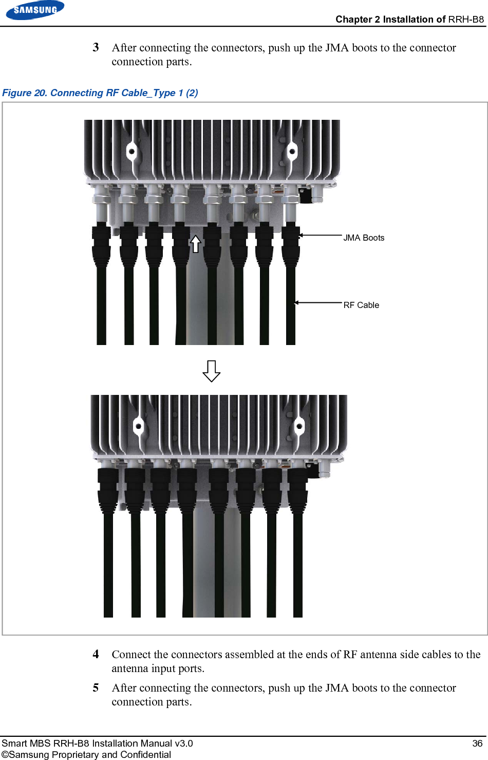
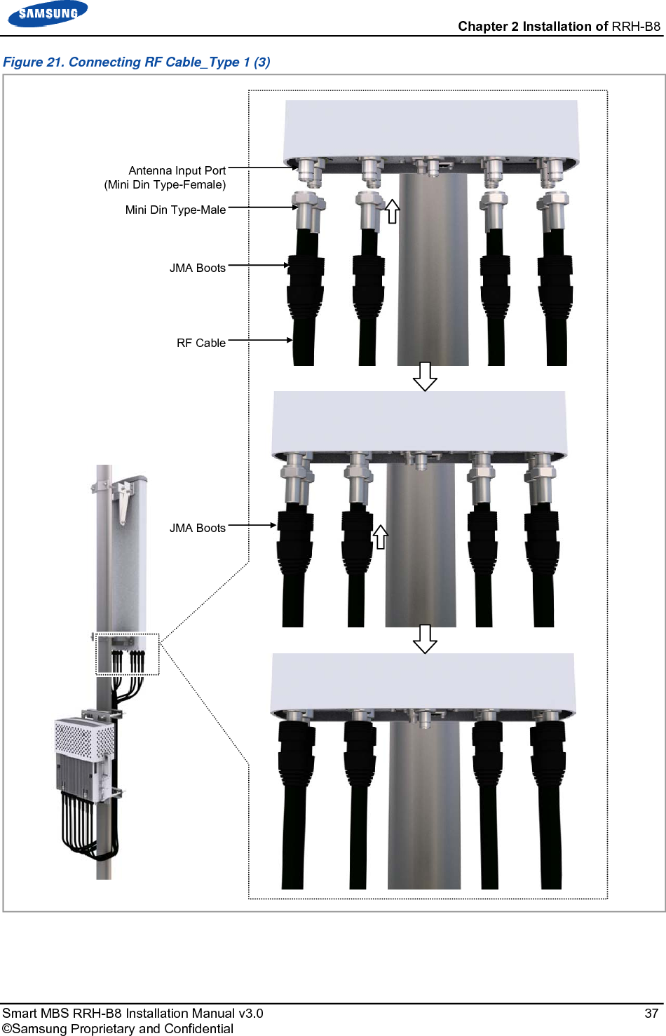
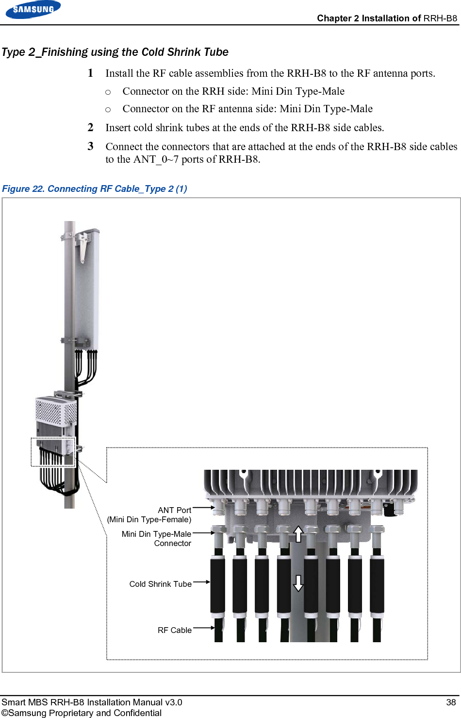
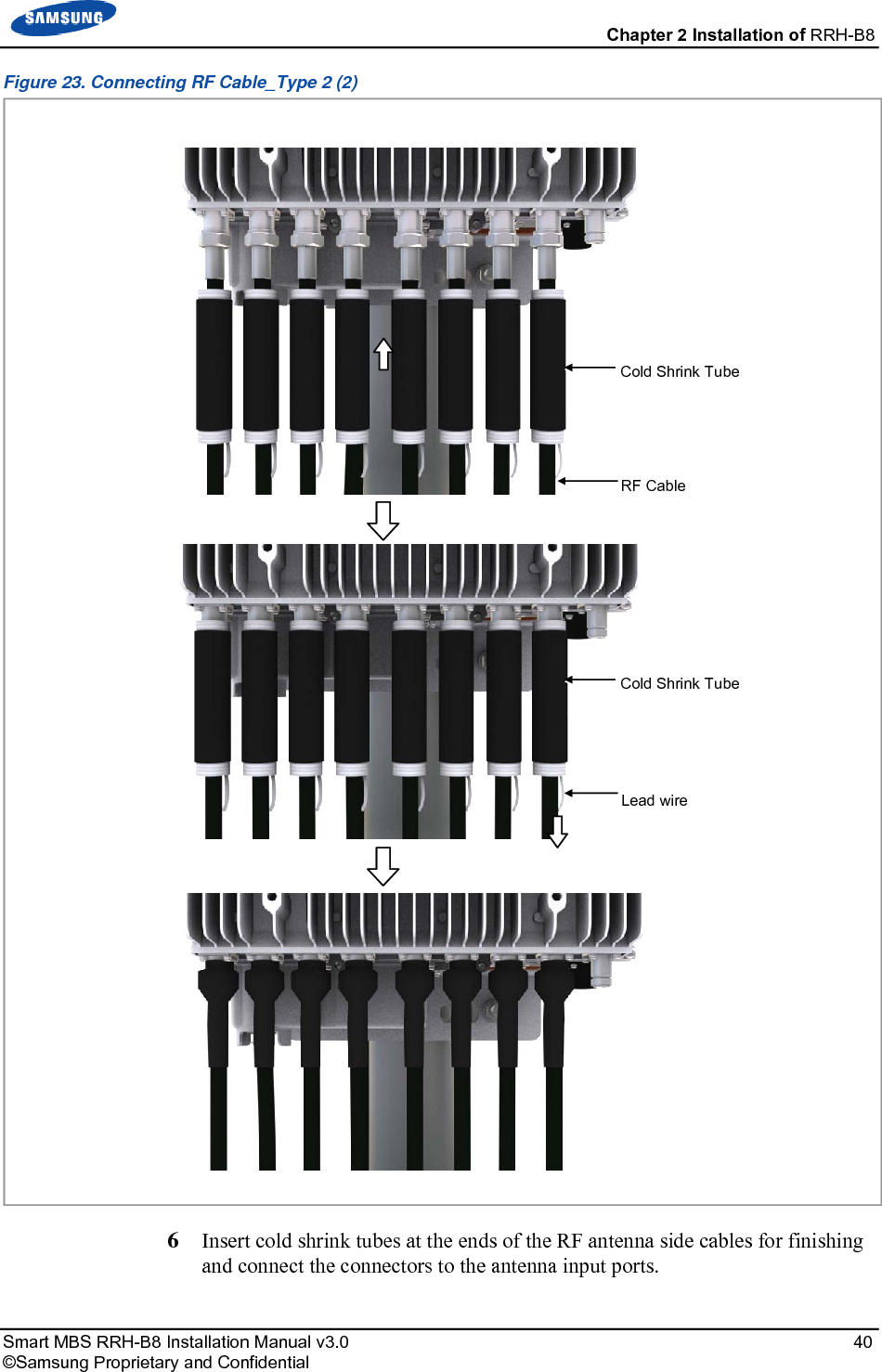
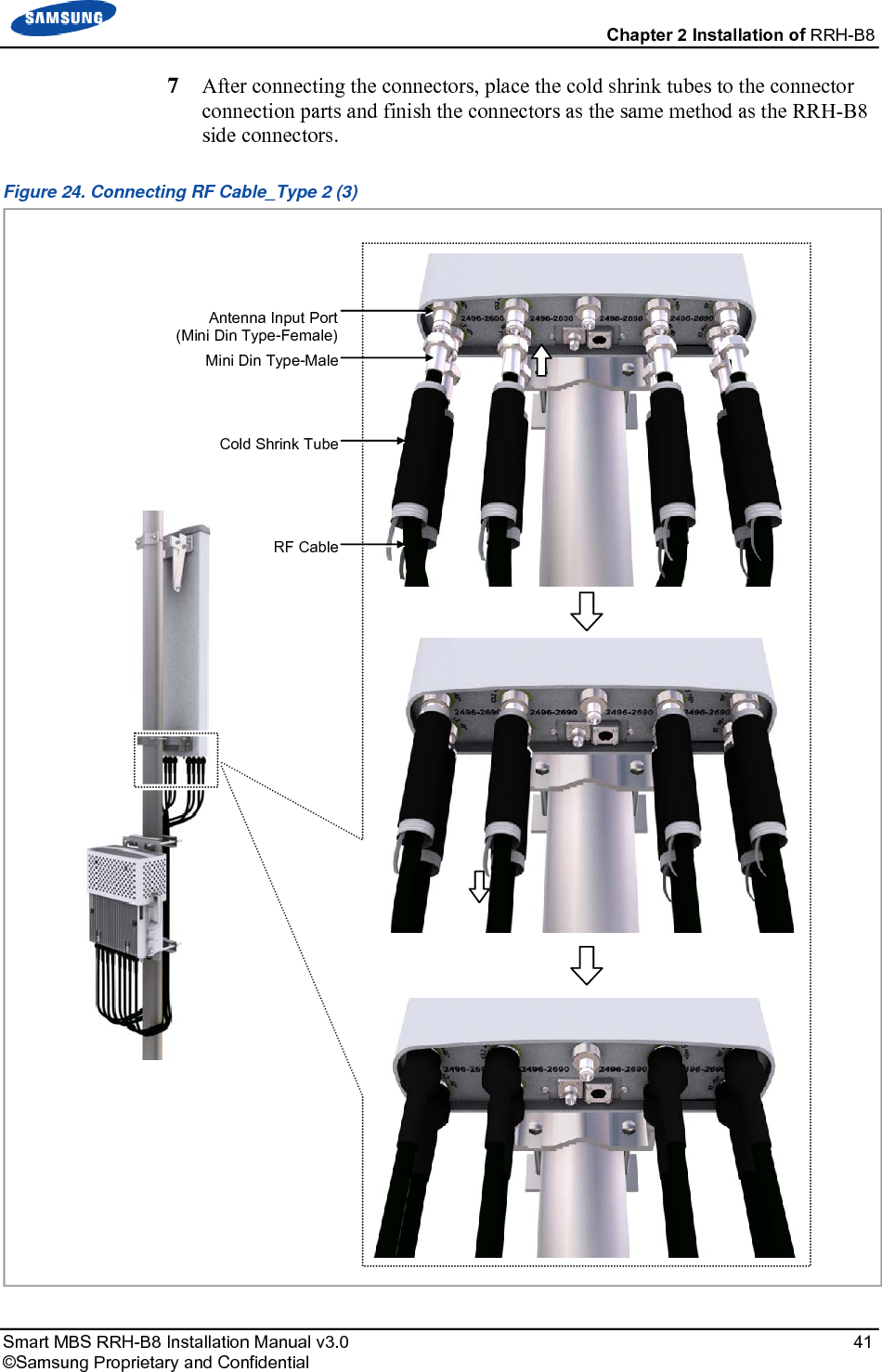
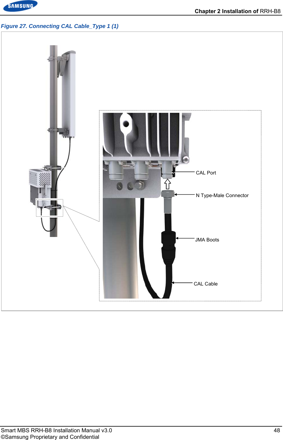
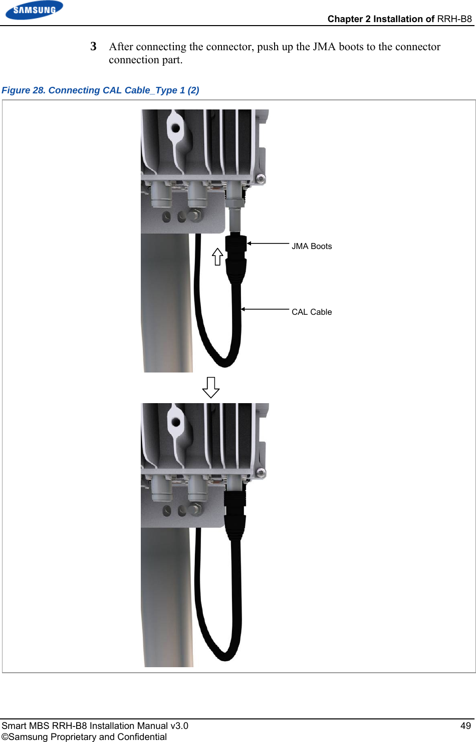
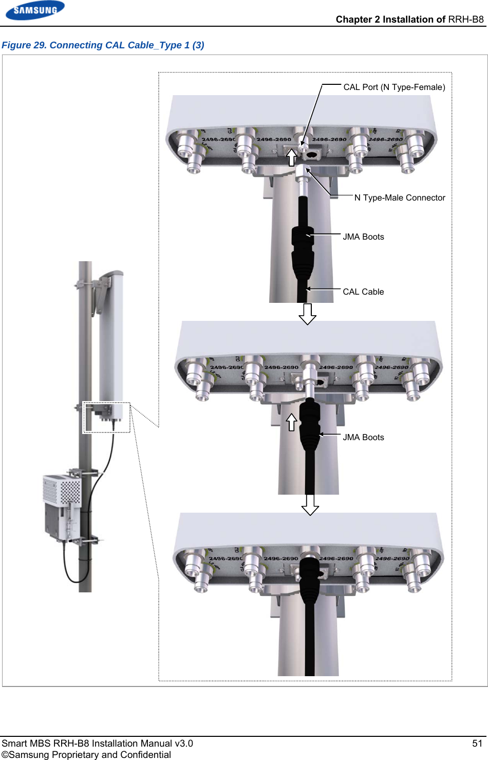
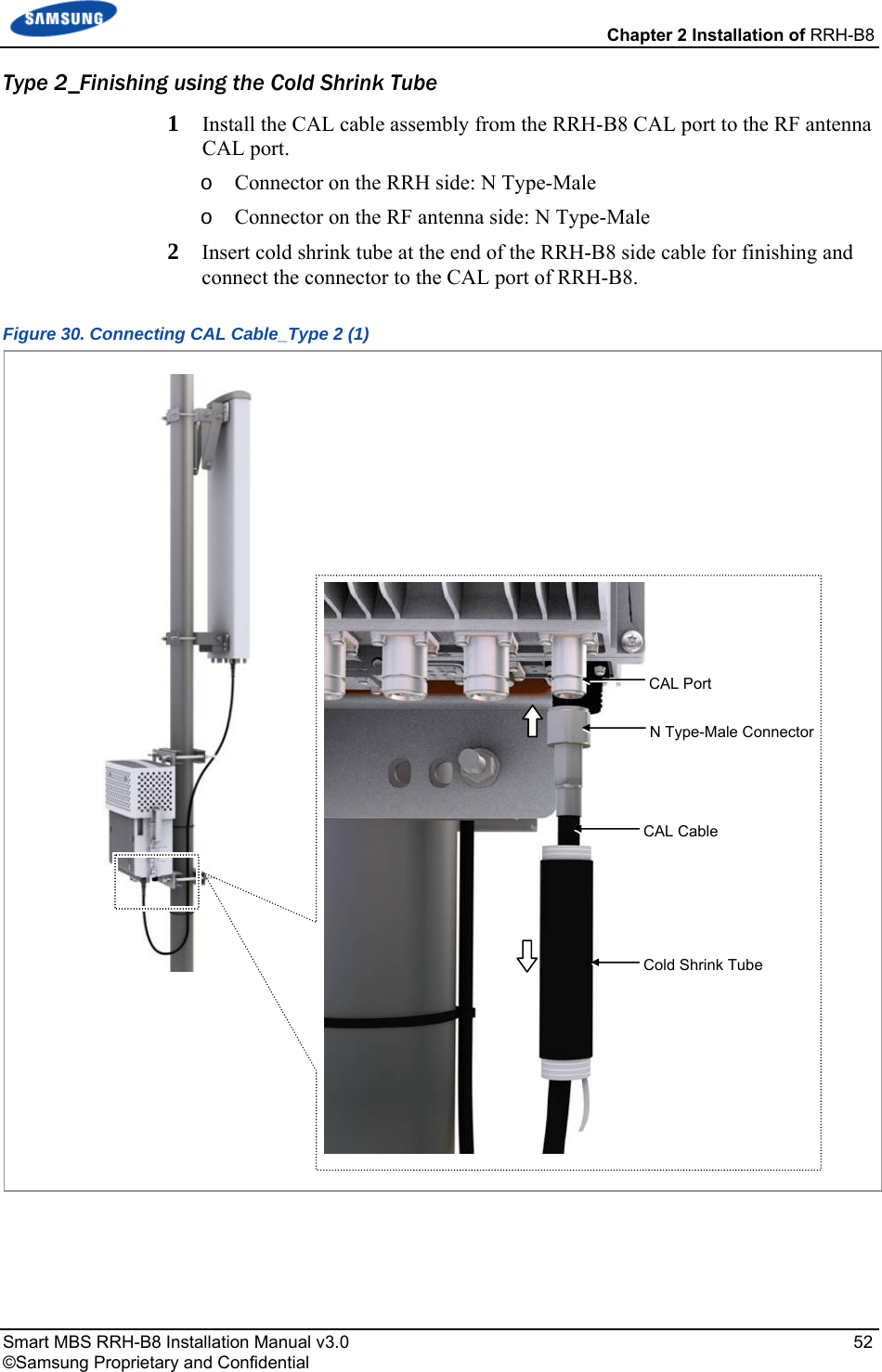
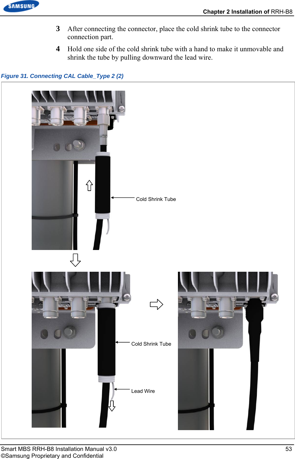
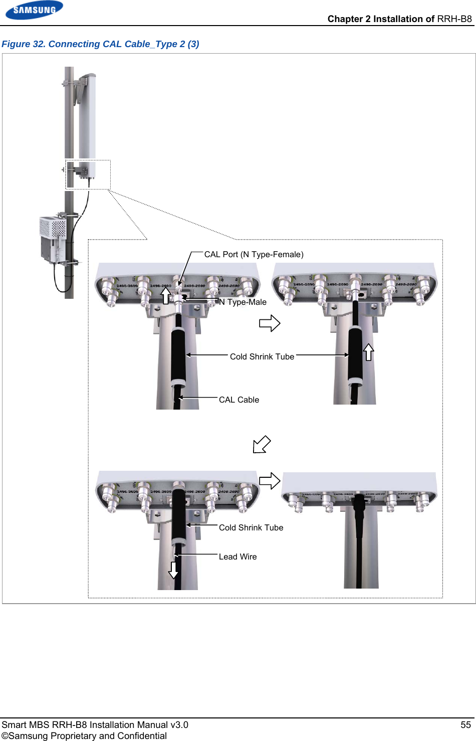
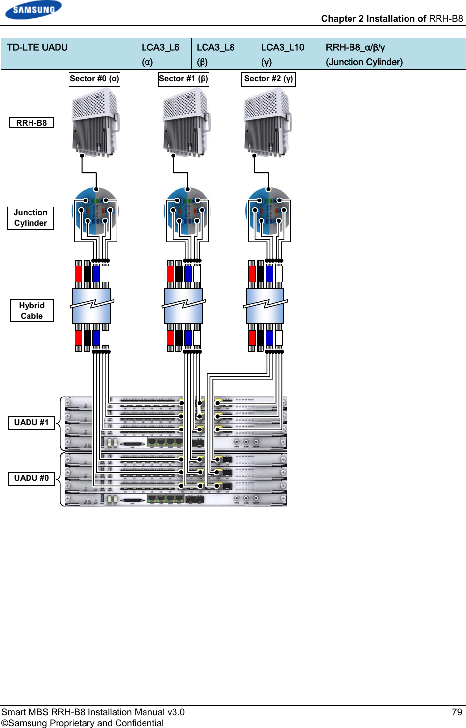
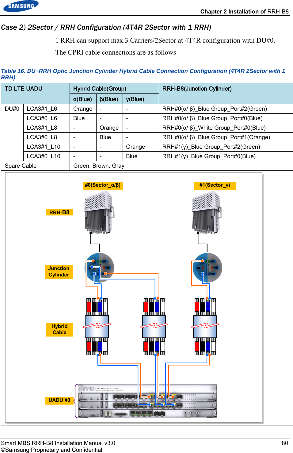
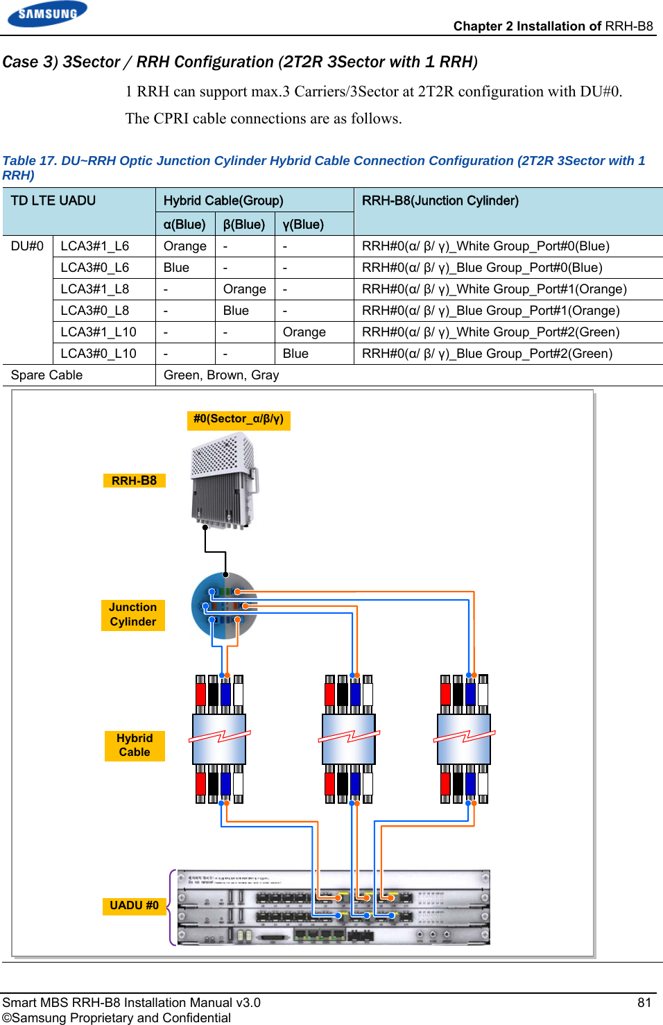
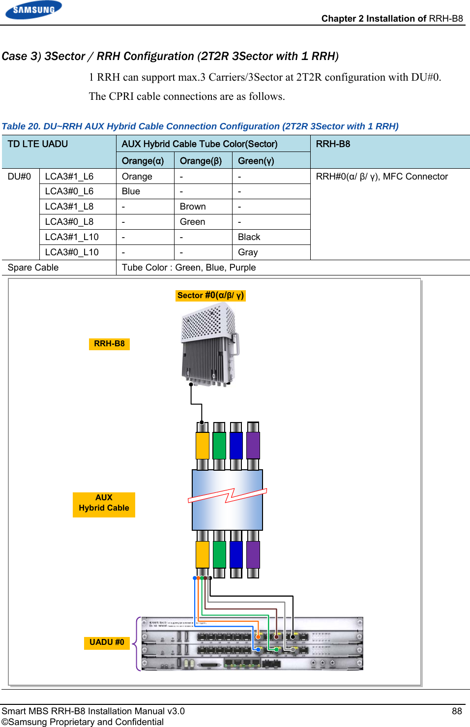
![Chapter 2 Installation of RRH-B8 Smart MBS RRH-B8 Installation Manual v3.0 33 ©Samsung Proprietary and Confidential Cabling The following shows the cables connected to RRH-B8. Figure 18. Cabling Diagram [RF Antenna] 1) TGB Ground Cable[TGB] Feeder Line Ground Cable (Ground Kit/7/8 in. Feeder Line or more) ※ TGB and Ground Kit are used in case of the 7/8 in. feeder line or more.[Rectifier] [UADU] 7) CPRI Cable 2) RF Cable 3) RET Cable 6) Power Cable 5) RRH-B8 Ground Cable 4) CAL Cable](https://usermanual.wiki/Samsung-Electronics-Co/SLS-BR02BQ.User-Manual-20151112-v1-SLS-BR02BQ-User-manual-rev02/User-Guide-2822460-Page-47.png)
![Chapter 2 Installation of RRH-B8 Smart MBS RRH-B8 Installation Manual v3.0 46 ©Samsung Proprietary and Confidential Figure 26. RET Cable Connector Table 13. RET Cable-Side Connector Pin Map Amphenol AISG Connector Male Function Female 1 +12 V Optional (N.C) 1 2 N.C 2 3 RS485 B 3 4 RS485 GND 4 5 RS485 A 5 6 +21 V 6 7 +21 V RTN 7 8 N.C 8 Make sure to turn off the breaker connected to the RRH-B8 power of the DU cabinet before connecting the RET cable between the antenna RET port and the RRH-B8 RET port. If you connect or disconnect the RET cable while the breaker is turned on, it may cause an electric short circuit resulting in damage to the RET function. When 21 VDC volts are applied, the current supplied to the RET from RRH-B8 must be 1 A or lower. The exterior of the RET connector must be made of metal without vent hole or other UL certified material. [RRH-B8-side Connector: AISG Male] [Antenna-side Connector: AISG Female] 6 8 1 4 2 5 3 7 8614 2 735](https://usermanual.wiki/Samsung-Electronics-Co/SLS-BR02BQ.User-Manual-20151112-v1-SLS-BR02BQ-User-manual-rev02/User-Guide-2822460-Page-60.png)
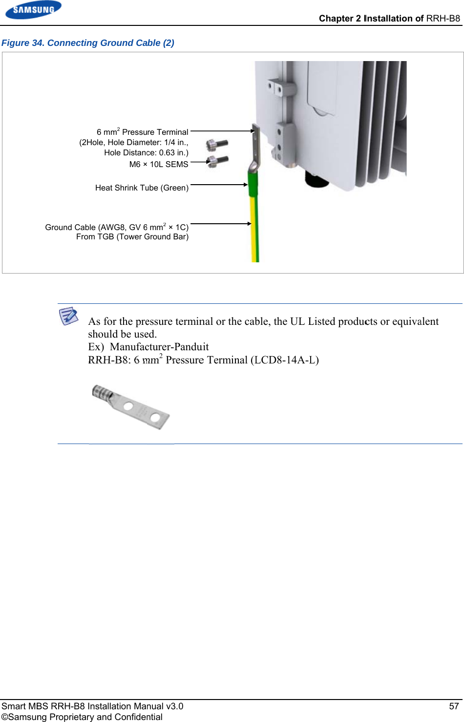
![Chapter 2 Installation of RRH-B8 Smart MBS RRH-B8 Installation Manual v3.0 56 ©Samsung Proprietary and Confidential Connecting Ground Cable Follow the steps below to connect the RRH-B8 ground cable. 1 Install one ground cable (AWG8, GV 6 mm2 × 1 C) from TGB to the ground terminal at the right of RRH-B8. Figure 33. Connecting Ground Cable (1) 2 Install the pressure terminal and the heat shrink tube at the end of the cable. o Pressure Terminal: 6 mm2, 2 hole, Hole Diameter: 1.4 in. (6.3 mm), Hole Distance: 0.63 in. (16 mm) 3 Place the pressure terminal at one end of the ground cable of RRH-B8 aligning with the fixing holes and fix it using M6 SEMS. (When being tighten by screw, apply 2.76~3.37 lbf.ft (38.16~46.64 kgf.cm) torque.) RRH-B8 Ground Cable [TGB]](https://usermanual.wiki/Samsung-Electronics-Co/SLS-BR02BQ.User-Manual-20151112-v1-SLS-BR02BQ-User-manual-rev02/User-Guide-2822460-Page-70.png)
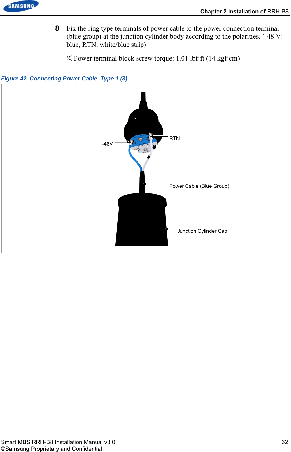
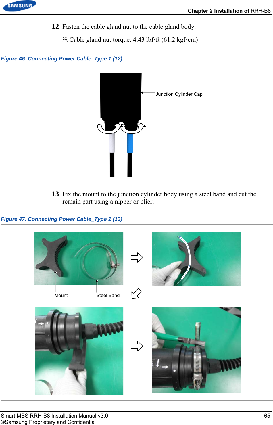

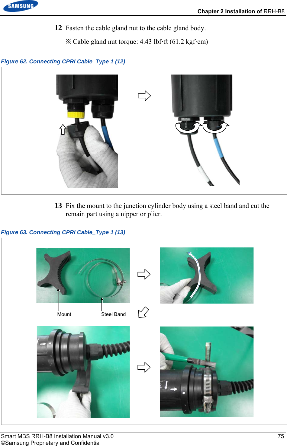
![Chapter 2 Installation of RRH-B8 Smart MBS RRH-B8 Installation Manual v3.0 69 ©Samsung Proprietary and Confidential Table 14. Power Connector Pin Map Connector Circular Connector 1: -48 V 2: RTN Cautions for the connecting a power cable to a connector are as follows: - Place the grooves of a cable side connector on the protrusions of a system side connector to fit into each other and connect them by turning a coupling nut on the top of the cable side connector. If the connectors are not aligned in a line, the connectors can be damaged when connecting the connectors. - Do not connect the power cable to the connector with excessive force as the connector may be damaged. - Do not forcefully pull the power cable or bend it beyond the allowed radius of curvature when fixing to the connector. To ensure stability in power supply, a circuit breaker must be installed on the power cable connected to the rectifier (or power distributor). Capacity of -48 VDC circuit breaker is 32 A. [Cable side Connector: JONHON, 003-00028953-01] [System side Connector: JONHON, 003-00028953-03] 1 1 2 2](https://usermanual.wiki/Samsung-Electronics-Co/SLS-BR02BQ.User-Manual-20151112-v1-SLS-BR02BQ-User-manual-rev02/User-Guide-2822460-Page-83.png)
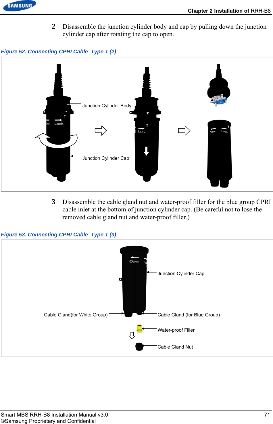
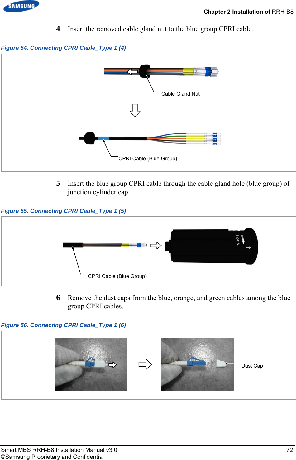
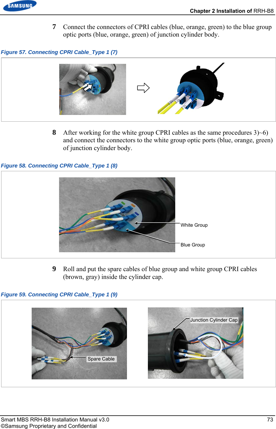
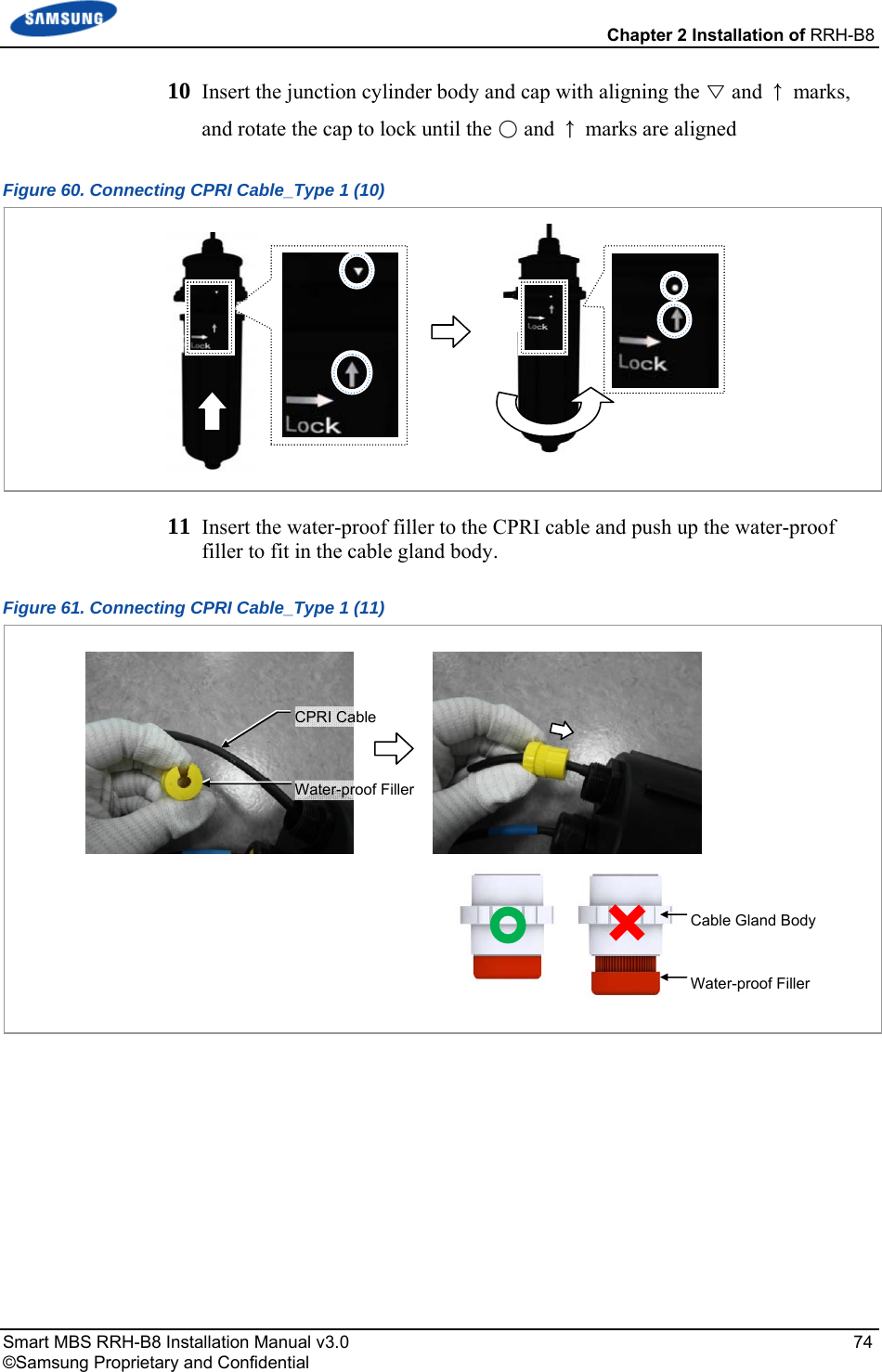
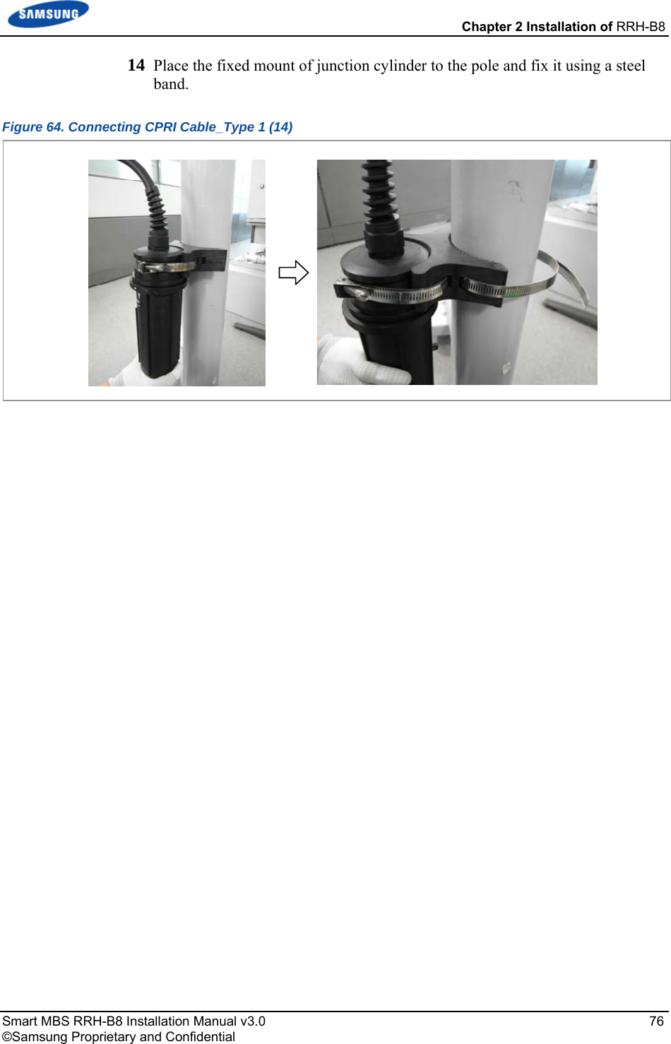
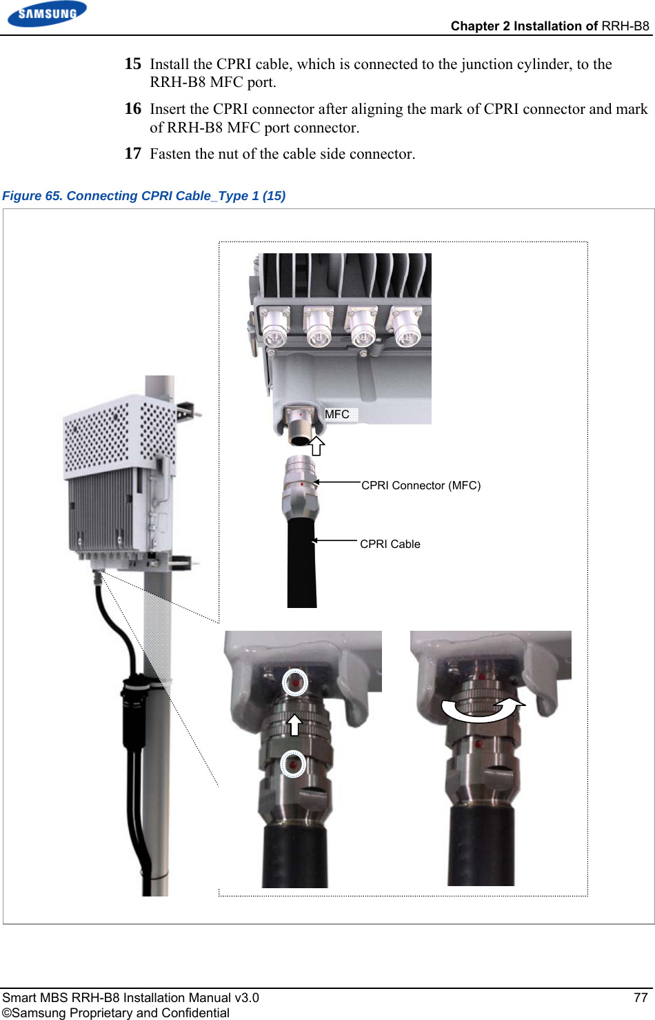
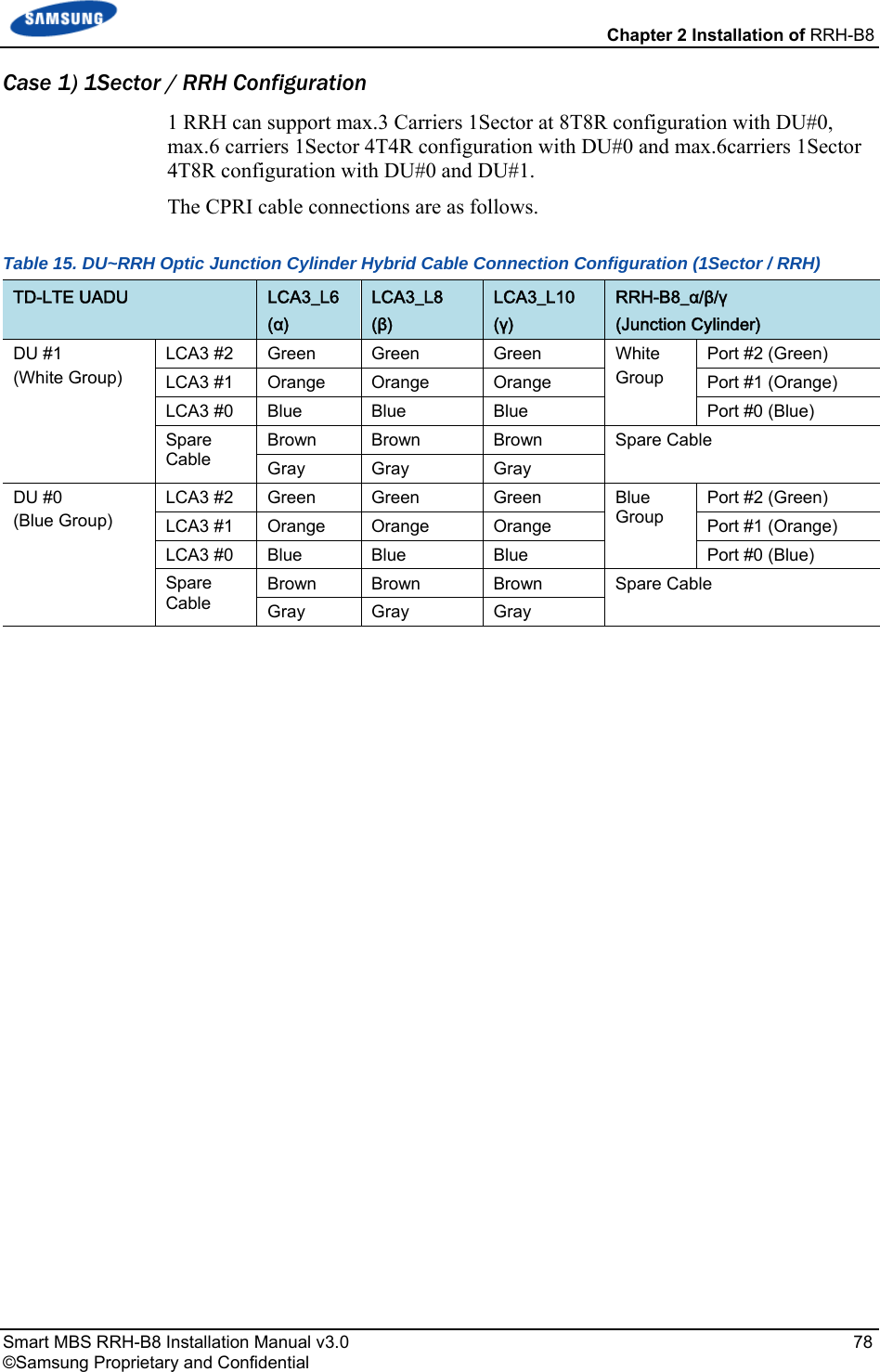
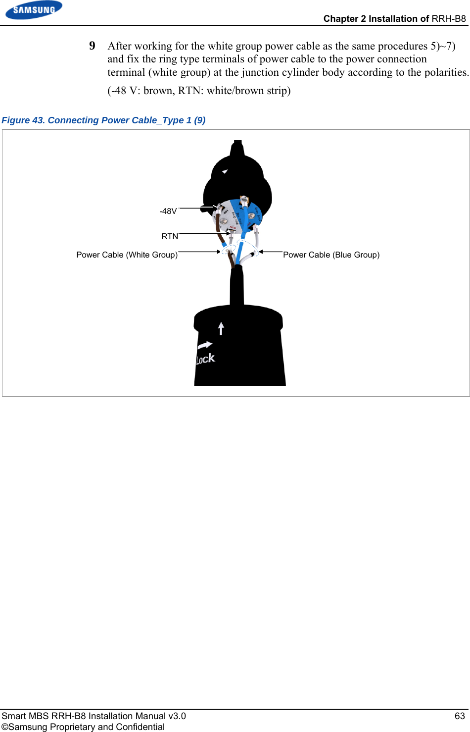
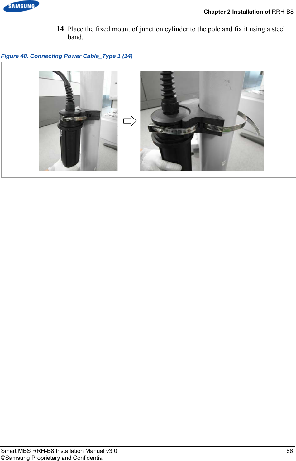
![Chapter 2 Installation of RRH-B8 Smart MBS RRH-B8 Installation Manual v3.0 83 ©Samsung Proprietary and Confidential Type 2_Using AUX Hybrid Cable 1 Install the AUX hybrid from the DU to the RRH-B8. 2 Insert the CPRI connector after aligning the mark of CPRI connector and mark of RRH-B8 MFC port connector. 3 Fasten the nut of the cable side connector. Figure 66. Connecting CPRI Cable_Type 2 [DU] CPRI Cable CPRI Connector (MFC) MFCCPRI Cable](https://usermanual.wiki/Samsung-Electronics-Co/SLS-BR02BQ.User-Manual-20151112-v1-SLS-BR02BQ-User-manual-rev02/User-Guide-2822460-Page-97.png)


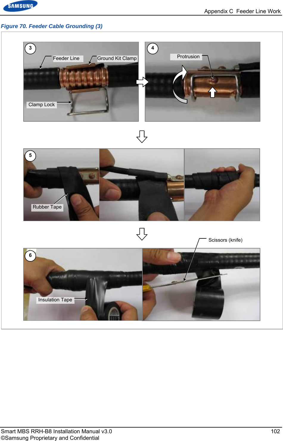
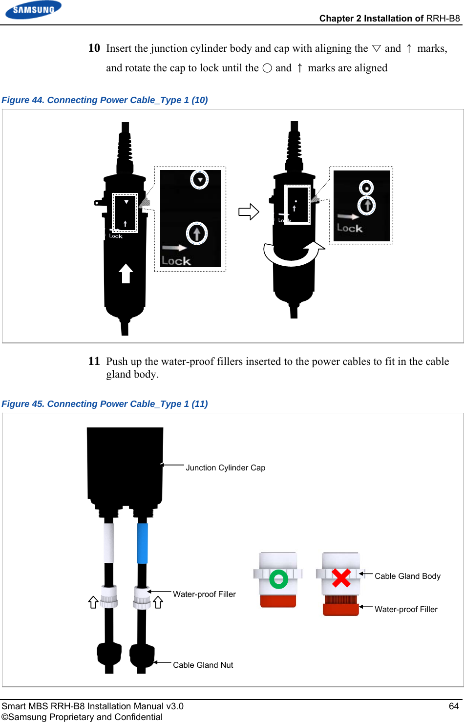
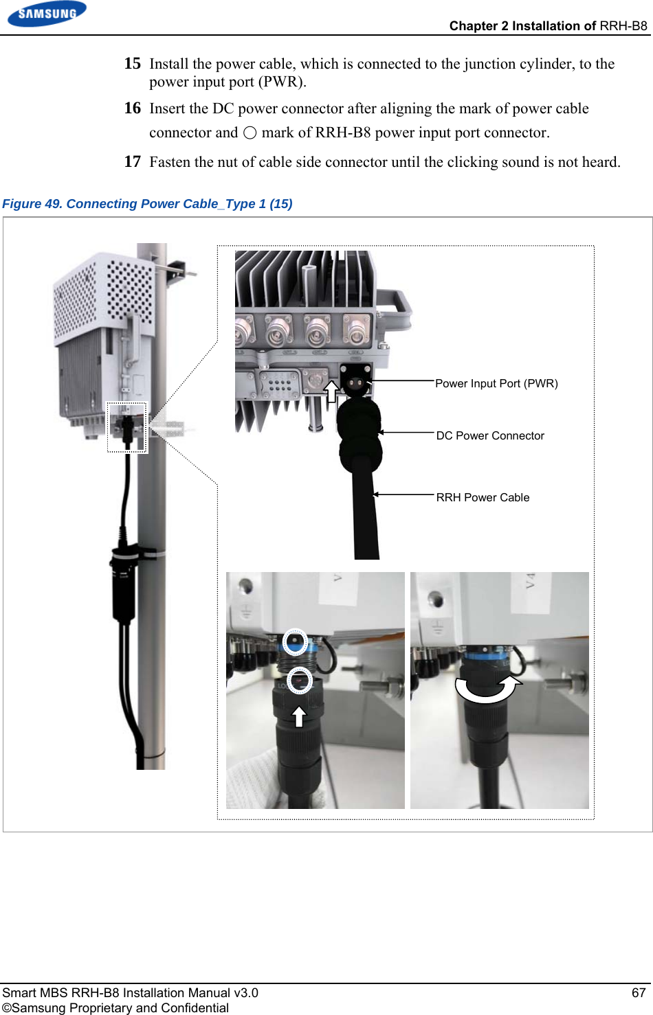
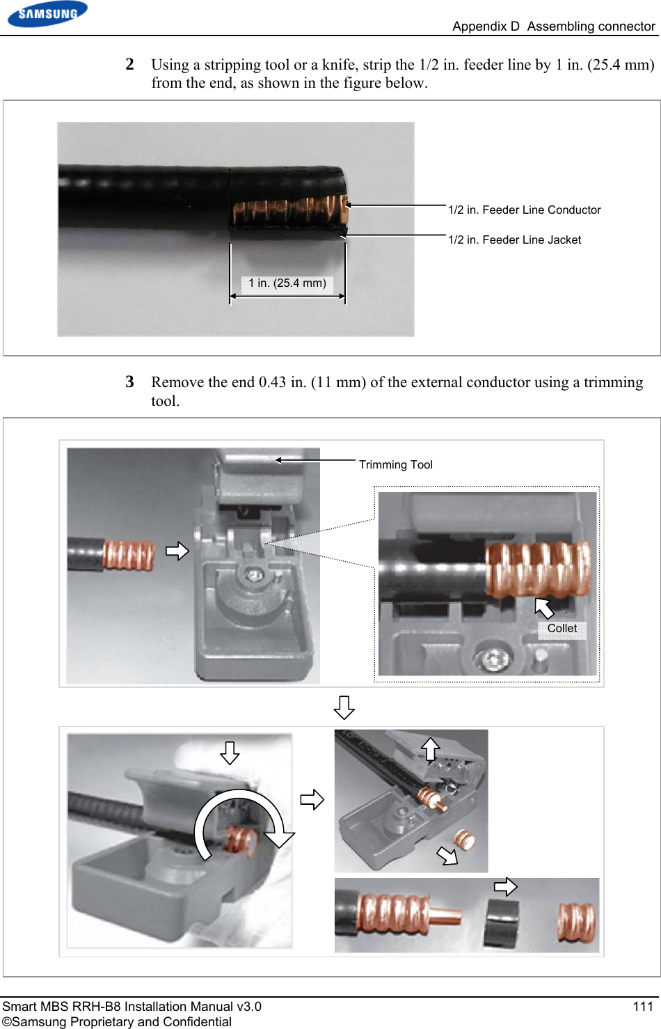
![Appendix C Feeder Line Work Smart MBS RRH-B8 Installation Manual v3.0 103 ©Samsung Proprietary and Confidential 7 Align the heat shrink tube, inserted when installing the feeder line, into the fixing part of the ground kit. o Heat shrink tube: Φ 1.65 in., 7.87 in (Φ 42 mm, 200 mm) 8 Shrink the heat shrink tube [jelly type, 7.87 in. (200 mm)] by heating gun. Figure 71. Feeder Cable Grounding (4) 7.87 in. (200 mm)Heating Gun Heat Shrink Tube Heat Shrink Tube7 8](https://usermanual.wiki/Samsung-Electronics-Co/SLS-BR02BQ.User-Manual-20151112-v1-SLS-BR02BQ-User-manual-rev02/User-Guide-2822460-Page-117.png)
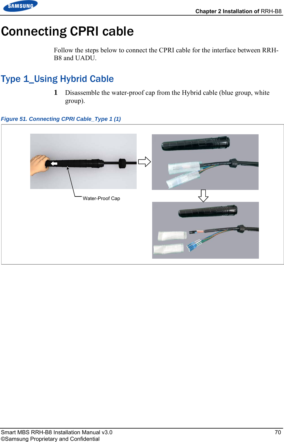
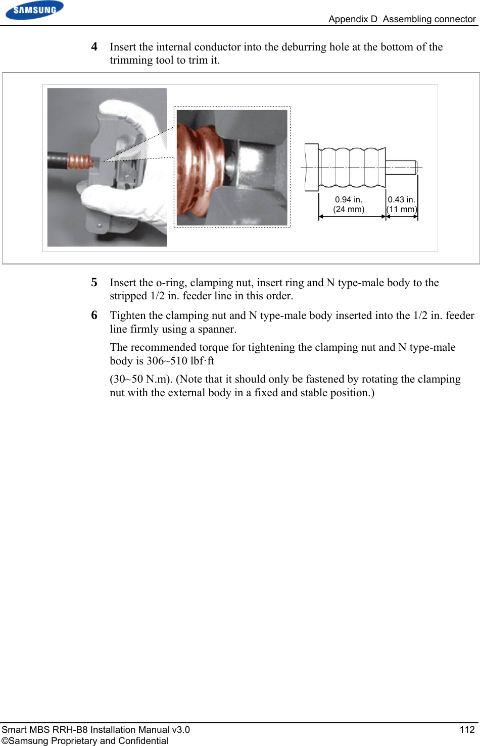
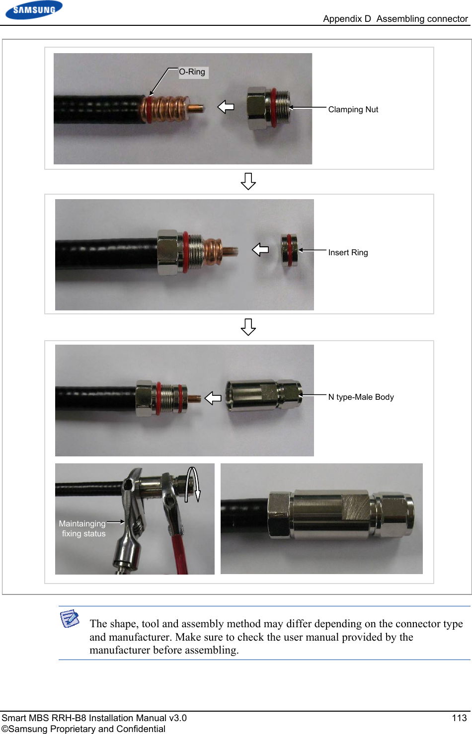
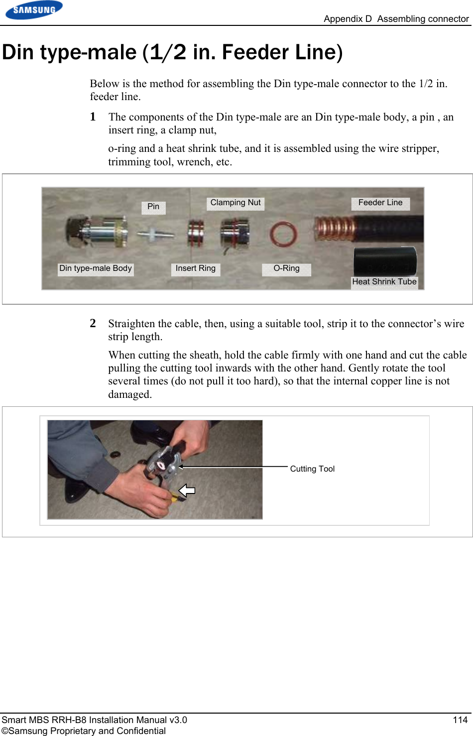
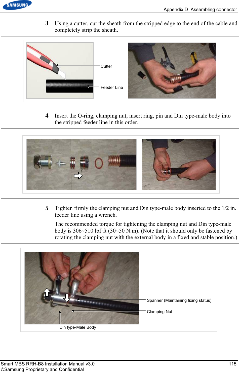
![Appendix D Assembling connector Smart MBS RRH-B8 Installation Manual v3.0 110 ©Samsung Proprietary and Confidential N type-male (1/2 in. feeder line) Below is the method for assembling the N-type-male connector to the 1/2 in. feeder line. 1 The components of the N type-male are an N type-male body, an insert ring, a clamp nut, O-ring, and a heat shrink tube, and it is assembled using the wire stripper, trimming tool, spanner, etc. Trimming Tool Heat Shrink Tube [1.1 in. (28 mm)] Insert RingN type-Male Body Clamping Nut 1/2 in. Feeder Line O-Ring](https://usermanual.wiki/Samsung-Electronics-Co/SLS-BR02BQ.User-Manual-20151112-v1-SLS-BR02BQ-User-manual-rev02/User-Guide-2822460-Page-124.png)

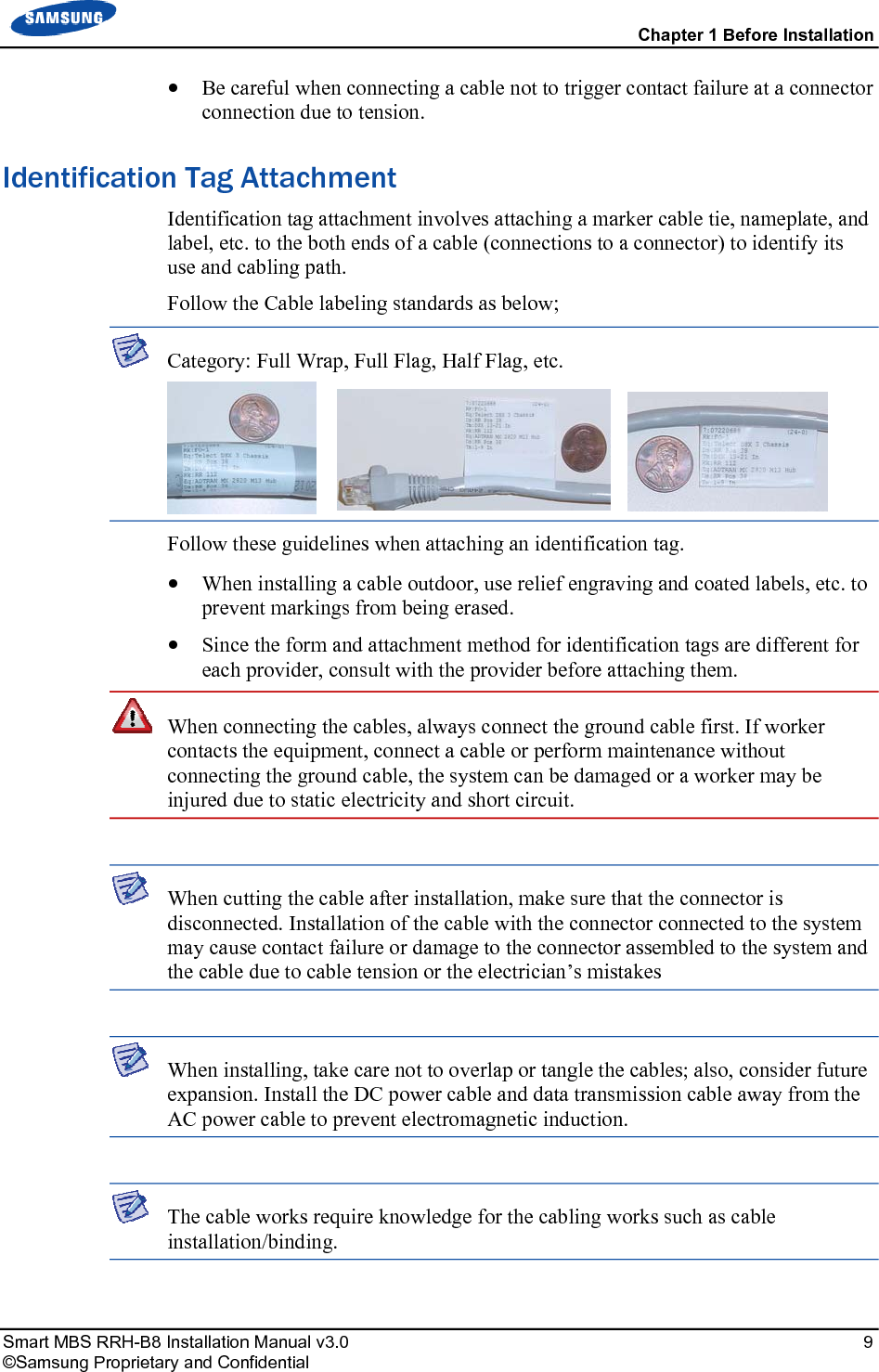
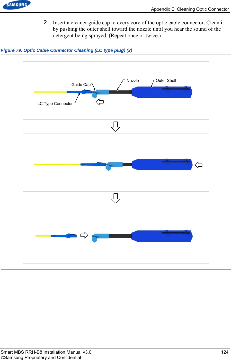
![Appendix E Cleaning Optic Connector Smart MBS RRH-B8 Installation Manual v3.0 120 ©Samsung Proprietary and Confidential IBCTM Brand Cleaner Method that uses IBCTM Brand Cleaner is as follows: IBCTM brand type cleaner (P/N 9393) Method that uses IBCTM Brand Cleaner (P/N 9393) for LC-LC and MU connector is as follows: Figure 75. Optic Connector Cleaner (IBCTM Brand Type Cleaner: P/N 9393) Outer Shell[Optic Connector Cleaner Configuration]Nozzle Guide CapLock Button (for Extend Nozzle)[Nozzle Extension] [In Case of LC type Connector (Plug)] Guide CapGuide Cap Cover [In Case of LC type Connector (Jack)] Guide CapLock Button (for Extend Nozzle)](https://usermanual.wiki/Samsung-Electronics-Co/SLS-BR02BQ.User-Manual-20151112-v1-SLS-BR02BQ-User-manual-rev02/User-Guide-2822460-Page-134.png)
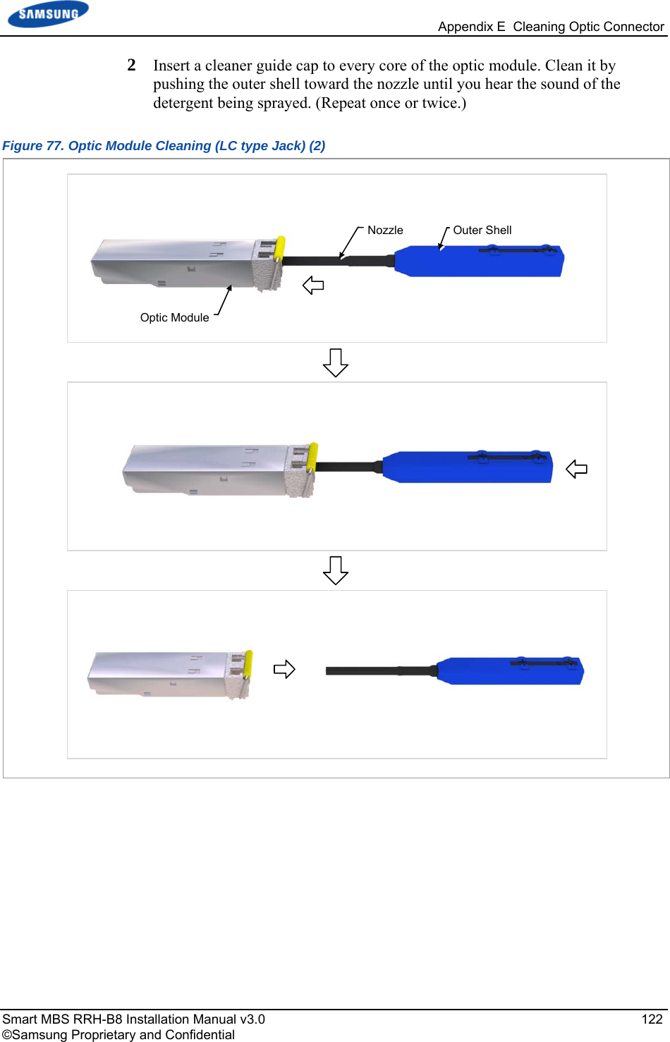
![Appendix E Cleaning Optic Connector Smart MBS RRH-B8 Installation Manual v3.0 121 ©Samsung Proprietary and Confidential Optic Module Cleaning (LC type Jack) 1 To clean the optic module, remove the guide cap from the cleaner (P/N: 9393). Figure 76. Optic Module Cleaning (LC type Jack) (1) Guide Cap Outer ShellNozzle [IBC Brand Cleaner: P/N 9393]](https://usermanual.wiki/Samsung-Electronics-Co/SLS-BR02BQ.User-Manual-20151112-v1-SLS-BR02BQ-User-manual-rev02/User-Guide-2822460-Page-135.png)
![Appendix E Cleaning Optic Connector Smart MBS RRH-B8 Installation Manual v3.0 123 ©Samsung Proprietary and Confidential Optic Cable Connector Cleaning (LC type plug) 1 To clean the optic cable connector, open the guide cap cover from the cleaner (P/N: 9393). Figure 78. Optic Cable Connector Cleaning (LC type plug) (1) Guide CapGuide Cap Cover Outer ShellNozzle [IBC Brand Cleaner: P/N 9393]](https://usermanual.wiki/Samsung-Electronics-Co/SLS-BR02BQ.User-Manual-20151112-v1-SLS-BR02BQ-User-manual-rev02/User-Guide-2822460-Page-137.png)
![Appendix E Cleaning Optic Connector Smart MBS RRH-B8 Installation Manual v3.0 125 ©Samsung Proprietary and Confidential Measuring the Optical Output and Connecting the Optic Connector 1 Check the optical output again using an optic power meter. 2 If the optical output measurement result meets the reference value, clean the connector again and connect it. If the measurement result does not meet the reference value, discard the cable, replace it with a new cable, and then clean the new one and connect it to the system. Figure 80. Measuring the Optical Output and Connecting the Optic Connector [Optic Powermeter] [LC/PC Plug]](https://usermanual.wiki/Samsung-Electronics-Co/SLS-BR02BQ.User-Manual-20151112-v1-SLS-BR02BQ-User-manual-rev02/User-Guide-2822460-Page-139.png)
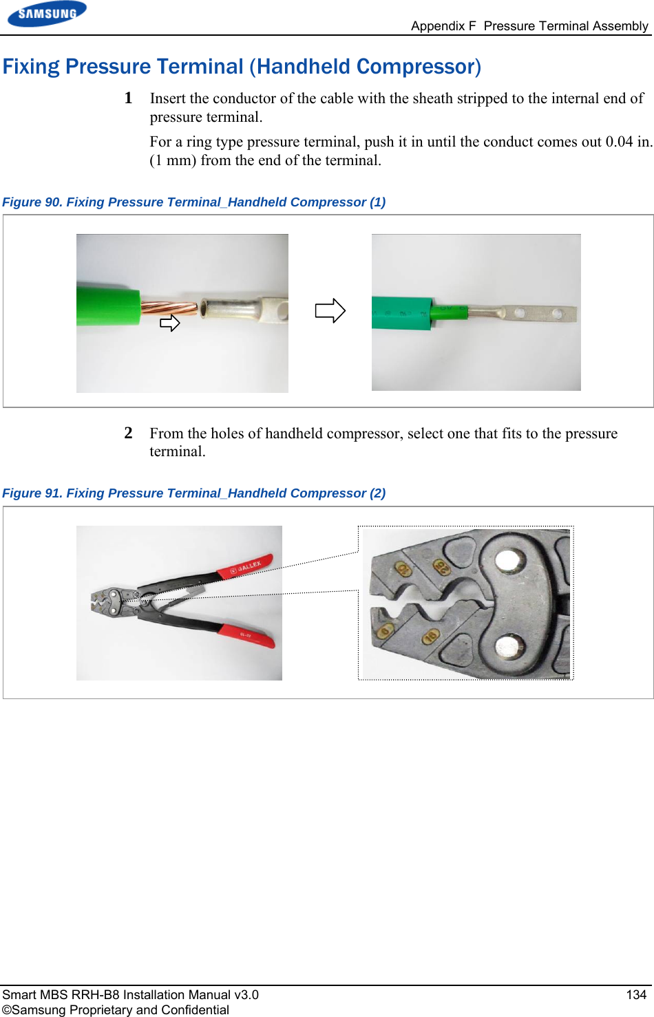
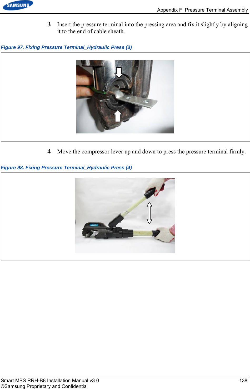
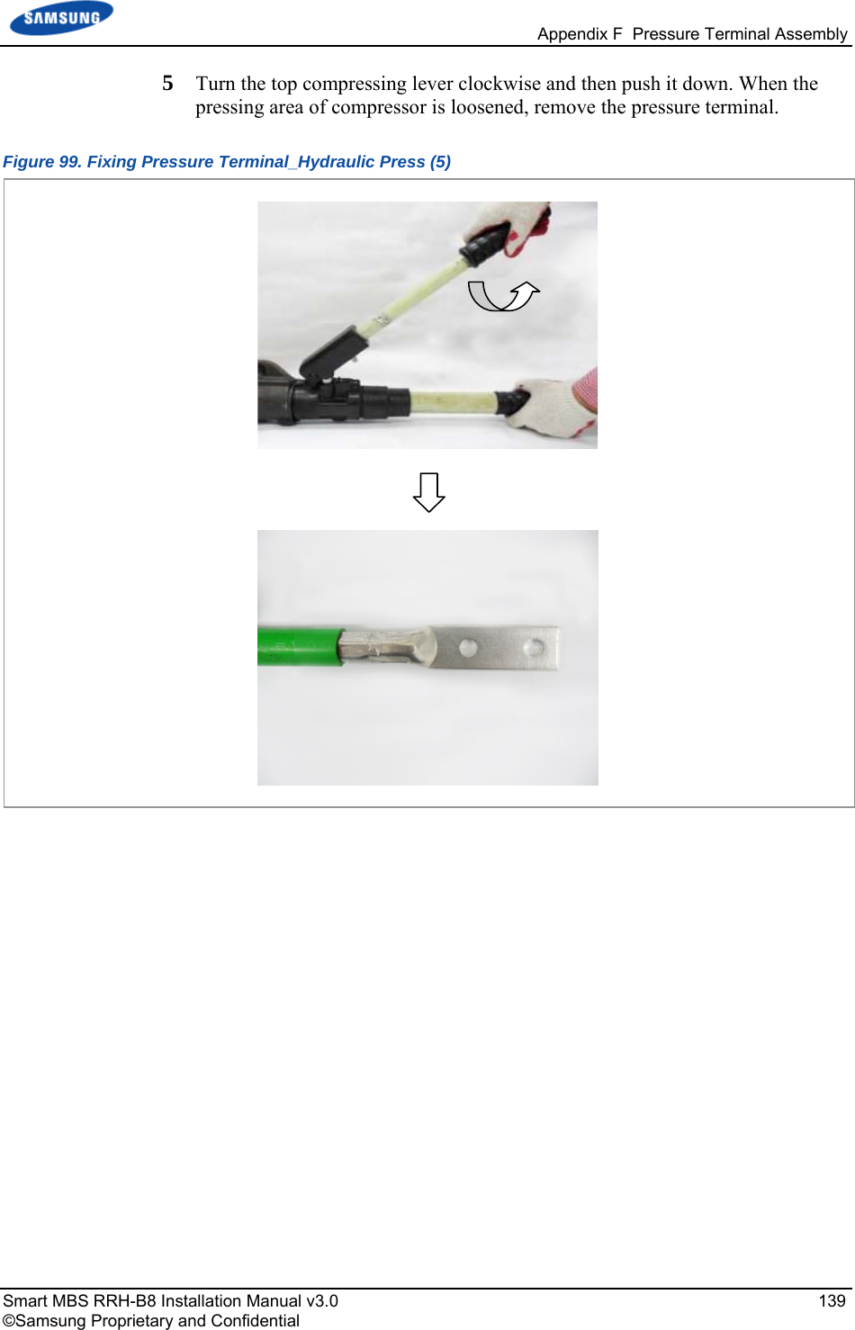
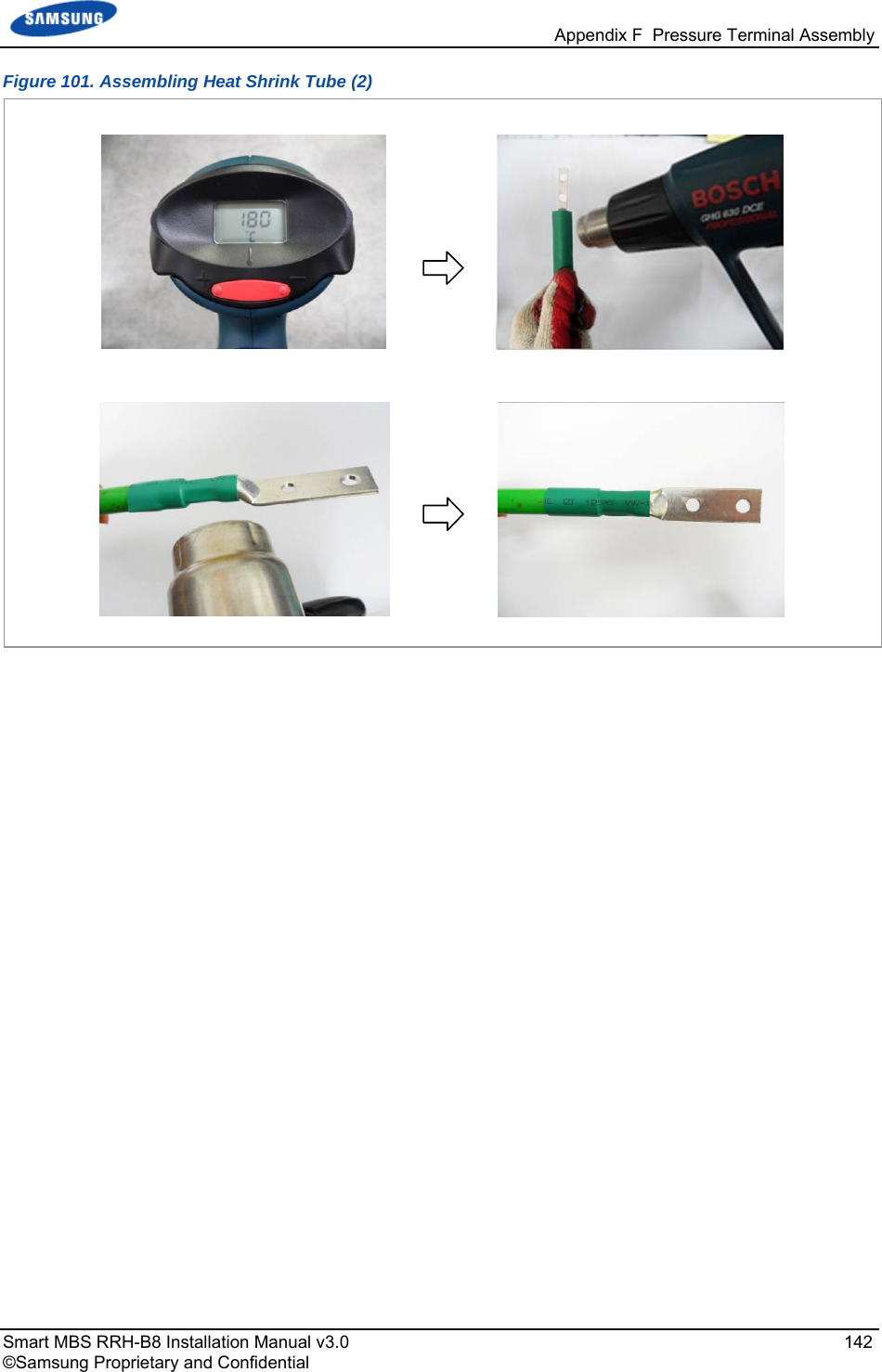
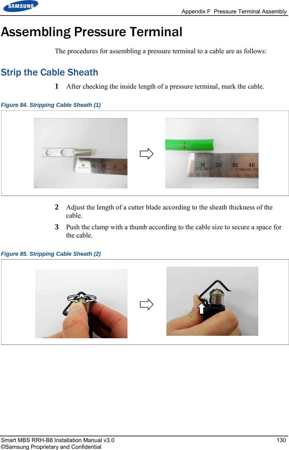
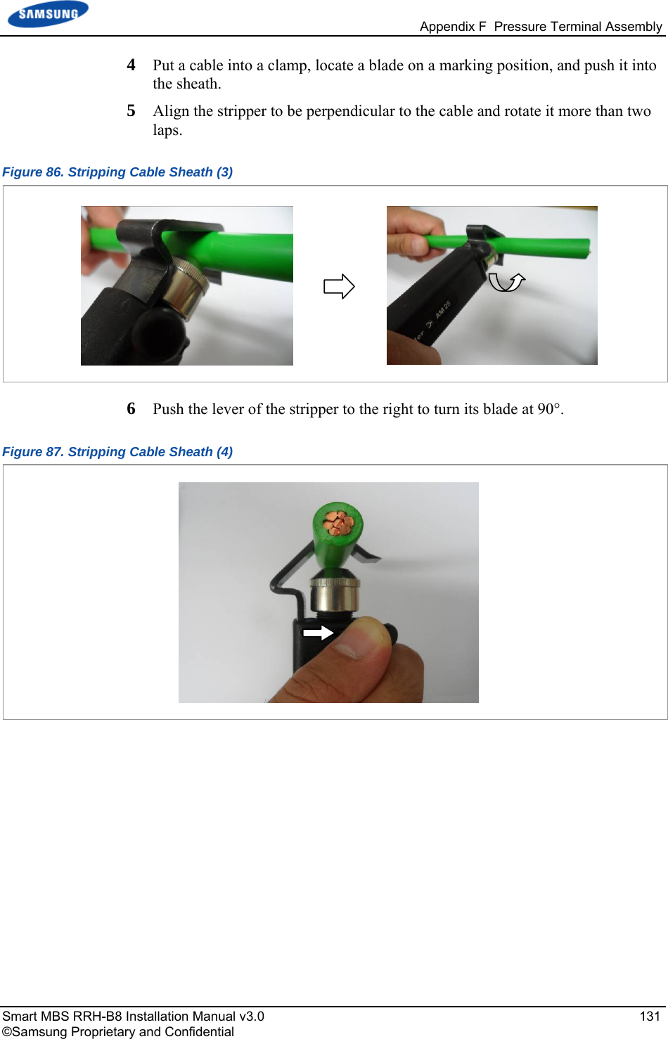
![Smart MBS RRH-B8 Installation Manual v3.0 126 ©Samsung Proprietary and Confidential Appendix F Pressure Terminal Assembly Preparations The followings must be prepared to connect a pressure terminal to a cable. Figure 81. Preparations [Cable Cutter] [Wire Stripper] [Handheld Compressor] [Hydraulic Press] [Heating Gun] [Marking Pen] [Cutter Blade] [Steel Ruler] [Scissors] [Cable] [Pressure Terminal][Heat Shrink Tube]](https://usermanual.wiki/Samsung-Electronics-Co/SLS-BR02BQ.User-Manual-20151112-v1-SLS-BR02BQ-User-manual-rev02/User-Guide-2822460-Page-140.png)
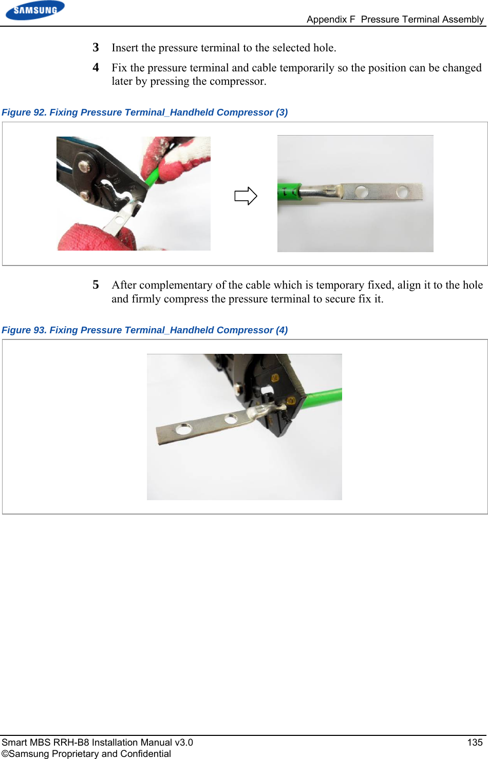
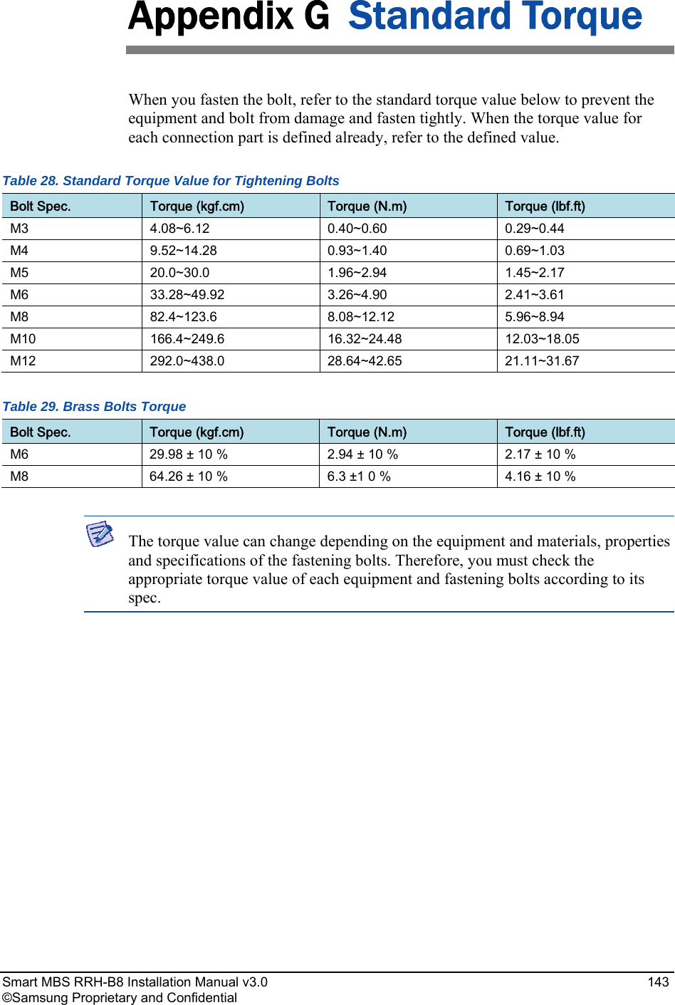
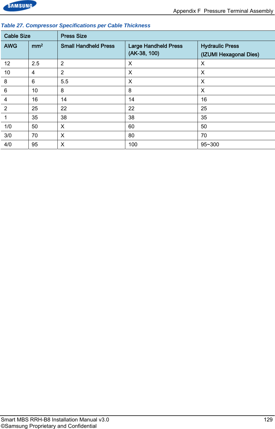
![Appendix F Pressure Terminal Assembly Smart MBS RRH-B8 Installation Manual v3.0 127 ©Samsung Proprietary and Confidential Pressure Reference Table The pressure reference table used to assemble a pressure terminal to a cable is shown below. Table 26. Pressure Reference Table for Pressure Terminal Category Copper tube length of a pressure terminal Number of pressure points In. mm Hand 0.43 in. or less 11 mm or less 1 Hand 0.47~0.59 in. 12~15 mm 2 Hand 0.63~0.91 in. 16~23 mm 3 Hand 0.94~1.26 in. 24~32 mm 4 Hand 1.3 in. or more 33 mm or more 5 Hydraulic 1.18 in. or less 30 mm or less 2 Hydraulic 1.22~1.85 in. 31~47 mm 3 Hydraulic 1.89~2.48 in. 48~63 mm 4 Hydraulic 2.52 in. or more 64 mm or more 5 Figure 82. Pressure Reference Drawing (Handheld Compressor) [1-spot] [2-spot] [3-spot] [4-spot] Unit: in. (mm) 0.43 (11) 0.18 (4.5) 0.47 (12) 0.59 (15) 0.63 (16) 0.91 (23) 0.94 in. (24) 1.26 (32) 0.63 (16) 0.18 (4.5) Copper Tube Starting Middle of Copper Tube Arbitrary Fixing Reference Points](https://usermanual.wiki/Samsung-Electronics-Co/SLS-BR02BQ.User-Manual-20151112-v1-SLS-BR02BQ-User-manual-rev02/User-Guide-2822460-Page-141.png)
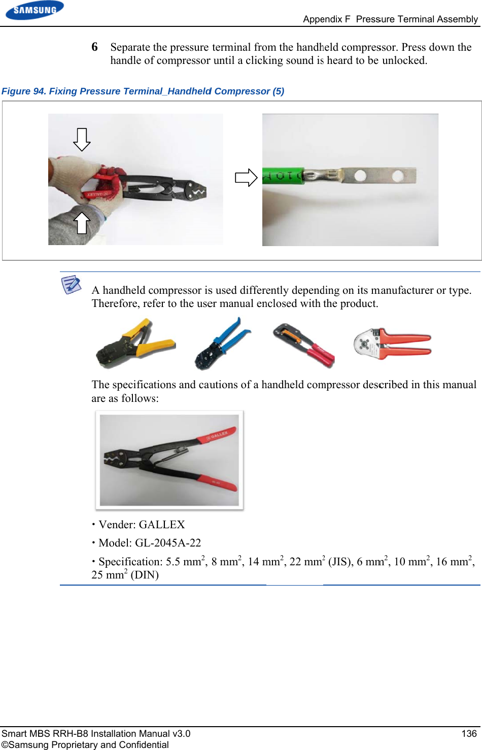
![Appendix F Pressure Terminal Assembly Smart MBS RRH-B8 Installation Manual v3.0 128 ©Samsung Proprietary and Confidential Figure 83. Pressure Reference Drawing (Hydraulic Press) Unit: in. (mm)[2-spot] [3-spot] [4-spot] 1.18 (30) [4-spot] Copper Tube Starting Duplicate Pressure Arbitrary Fixing Reference Points 0.53 (13.5) 1.22 (31) 0.53 (13.5) 1.22 (31) 1.85 (47) 1.89 (48) 2.48 (63) 2.52 (64)](https://usermanual.wiki/Samsung-Electronics-Co/SLS-BR02BQ.User-Manual-20151112-v1-SLS-BR02BQ-User-manual-rev02/User-Guide-2822460-Page-142.png)
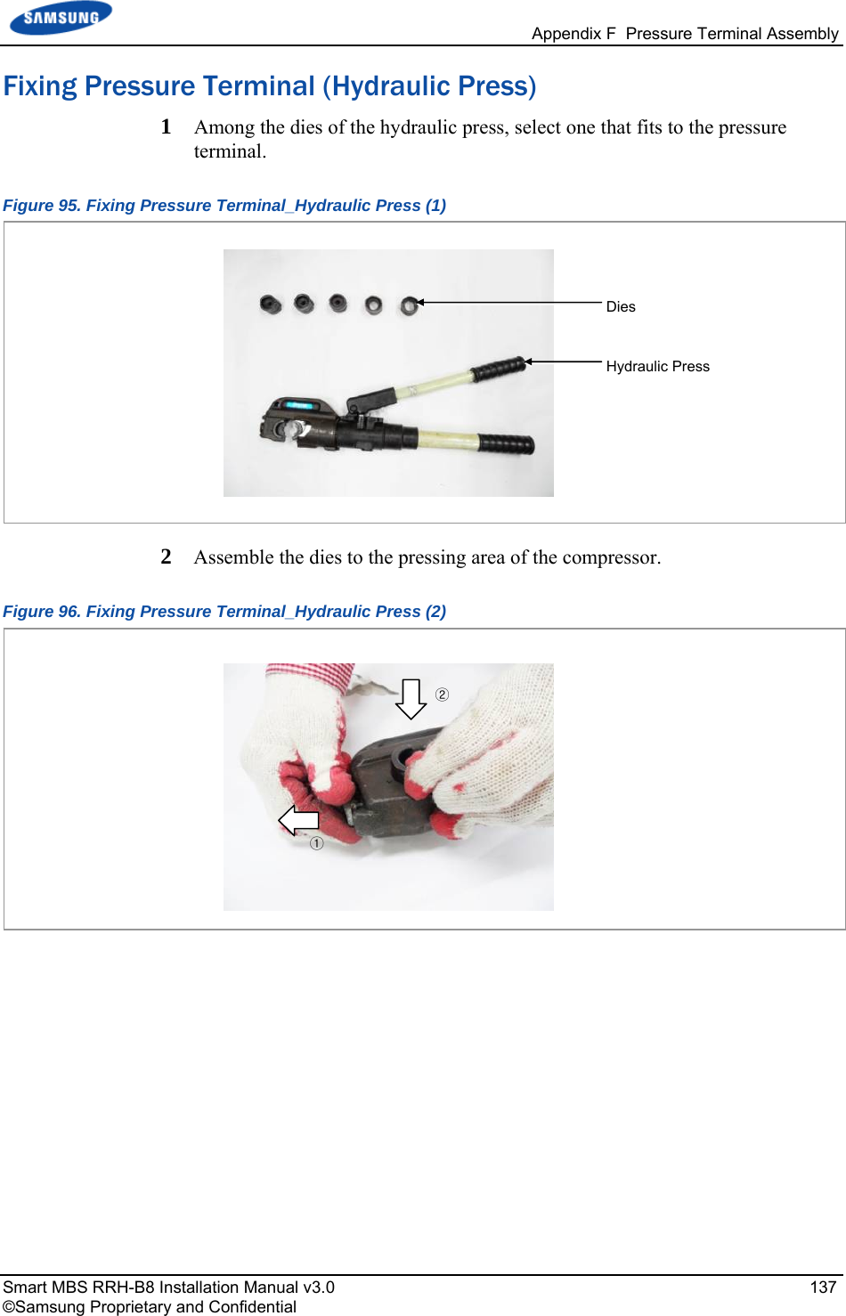
![Smart MB©Samsun BS RRH-B8 Inng Proprietary AT Tfo 0 - a - - nstallation May and ConfidenA wire strippTherefore, refThe specificafollows: Vender: WeModel: WeiSpecificatio0.18 in. (4.5 mTo prevent tadjust the lenMake sure tRotate the wnual v3.0 ntial er is used differ to the useations and caueidmuller idmuller-AMons: For outemm) clothingthe cutter blangth of cutterthat the cuttewire stripper [X] fferently deper manual enutions of a w M25 (Order Ner diameter 0g cutting depade of a wirer blade by cher blade goes perpendiculaAppepending on itnclosed with wire stripper No-90010800.24-0.94 in. (pth e stripper fromhecking the cinto the cabarly to the caendix F Pressts manufactuthe product. described in 000) (6-24 mm) Pm touching table sheath tle sheath comable. [O] sure Terminal urer or type. n this manualPVC clothingthe cable conthickness. mpletely. Assembly 133 are as g Up to nductor,](https://usermanual.wiki/Samsung-Electronics-Co/SLS-BR02BQ.User-Manual-20151112-v1-SLS-BR02BQ-User-manual-rev02/User-Guide-2822460-Page-147.png)