Sensys Gatso Netherlands
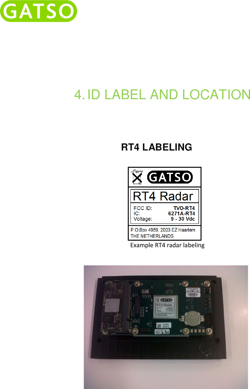
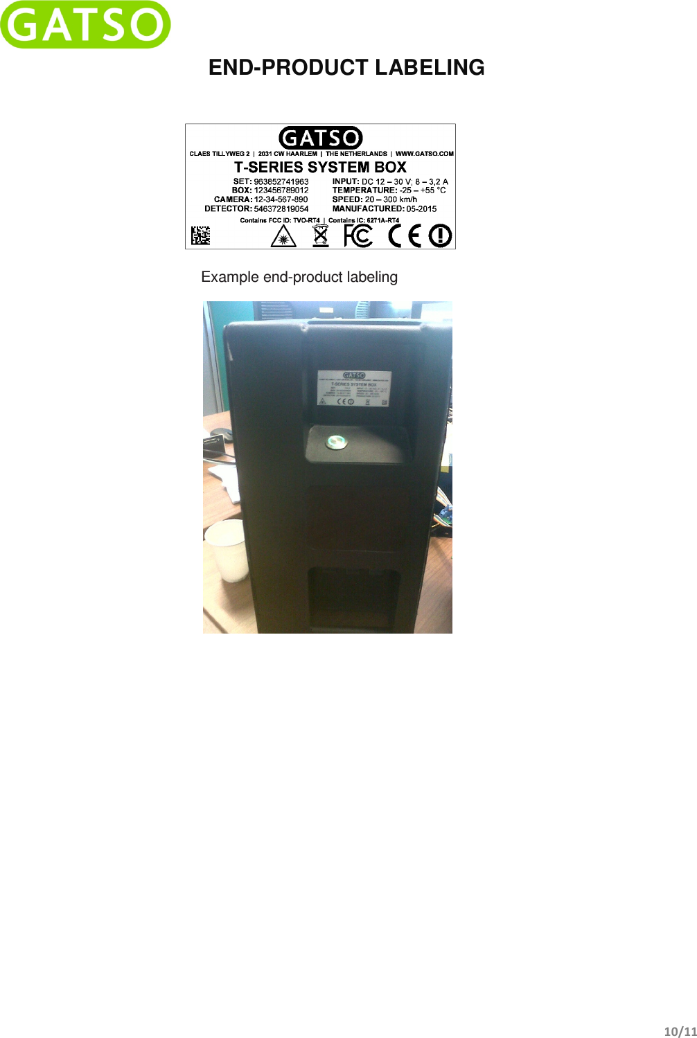
 RT4 RT4 User Manual DD 48 01 RT4 V12x

Gatsometer BV RT4 DD 48 01 RT4 V12x

UserManual.pdf

 USER MANUAL DD-48-01 RT4 RADAR      Gatsometer BV Claes Tillyweg 2 2031 CW, Haarlem P.O. Box 4959  Tel.: +31 (0) 23 525 50 50 Fax: +31 (0) 23 527 69 61 Mail: info@gatsometer.com
   2/11    DISCLAIMER   Copyright © 2015 - Gatsometer BV - The Netherlands   None  of  the materials provided on this technical manual may be  used,  reproduced  or  transmitted  in any form or by any means, electronic or mechanical, including recording or the use of any information storage and retrieval system, without written permission from Gatsometer BV. If you received this technical manual in  error,  please  notify  Gatsometer  BV  immediately.  The  confidential  nature  of  and/  or  privilege  in  the technical manual enclosed is not waived or lost as a result of a mistake or error in this technical manual.  Gatsometer BV accepts no liability whatsoever, whether it was caused by: 1. Accessing or other related actions to this manual. 2. Actions other than stated in this user manual  Gatsometer  BV  assumes  that  all  users  understand  risks  involved  within  this  user  manual  and/  or  its attached materials. All  components used can  be replaced by factory approved  equivalents. Drawings are subject to change without prior notice.  Translation disclaimer  The translation of this documents is done with the utmost care. However, Gatsometer B.V. does not accept any liability for the correctness and completeness of the compilation and content of this translation and the direct or indirect consequences of acting or failing to act based on these translations. It is not possible to derive any rights, of whatever nature, from the compilation and contents of the translations. In all cases, the original English document shall be decisive.   All  rights  reserved.  Compiled  by  Gatsometer  BV.    Please  contact info@gatsometer.com  for  more  information.  Gatsometer  follows  the  ROHS (Restriction of Hazardous Substances 2002/95/EC) and WEEE (Waste Electrical and Electronic Equipment) directives.  For the customers in Europe To  comply  with  European  directive  2002/96/EC  on  Waste  Electrical  and  Electronic Equipment (WEEE) this equipment must be recycled or disposed of properly. You can help preserve our environment by returning your used equipment to the distributor or the collection and recycling depot nearest to you.
   3/11  FCC and IC Declarations Compliance statement (part 15.19)  This device complies with part 15 of the FCC Rules and to RSS210 of Industry Canada. Operation is subject to the following two conditions: (1) this device may not cause harmful interference, and (2) this device must accept any interference received, including interference that may cause undesired operation. Le présent appareil est conforme aux CRN d’Industrie Canada applicables aux appareils radio exempts de licence. L’exploitation est authorisée aux deux conditions suivantes: (1) l’appareil ne doit pas produire de brouillage, et (2) l’utilisateur de l’appareil doit accepter tout brouillage radioélectrique subi, même si le brouillage est susceptible d’en compromettre le fonctionnement. INDUSTRY CANADA INFORMATION (additional) This device complies with RSS-210 of the Industry Canada Rules. This class B digital apparatus complies with Canadian ICES-003 This equipment should be installed and operated with a minimum distance of 20 cm between the radiator and your body. The final end-product must be labeled in a visible area with the following: “Contains IC: 6271A-RT4”. AVIS D’INDUSTRIE CANADA (supplémentaire): Cet appareil est conforme à la norme CNR-210 des règlements d’Industrie Canada. Cet appareil numérique de la classe B est conforme à la norme NMB-003 du Canada Avis d’Industrie Canada sur l’exposition aux Rayonnements: Cet équipement doit être installé et utilisé à une distance minimale de 20 cm entre le radiateur et votre corps. Le produit final final doit être étiqueté dans un endroit visible par le texte suivant: "Contains IC: 6271A-RT4". Warning (part 15.21) Changes or modifications not expressly approved by the party responsible for compliance could void the user’s authority to operate the equipment. This in particular is applicable for the antenna which has been delivered with the  RF Exposure (OET Bulletin 65) To comply with FCC RF exposure requirements for mobile transmitting devices, this transmitter should only be used or installed at locations where there is at least 20cm separation distance between the antenna and all persons. Information to the User (Part 15.105 (b)) Note: This equipment has been tested and found to comply with the limits for a Class B digital device, pursuant to part 15 of the FCC Rules. These limits are designed to provide reasonable protection against harmful interference in a residential installation. This equipment generates, uses and can radiate radio frequency energy and, if not installed and used in accordance with the instructions, may cause harmful interference to radio communications. However, there is no guarantee that interference will not occur in a particular installation. If this equipment does cause harmful interference to radio or television reception, which can be determined by turning the equipment off and on, the user is encouraged to try to correct the interference by one or more of the following measures: --Reorient or relocate the receiving antenna. --Increase the separation between the equipment and receiver. --Connect the equipment into an outlet on a circuit different from that to     which the receiver is connected. --Consult the dealer or an experienced radio/TV technician for help. Module integration instructions: This device is intended only for integration under the following conditions: (I).The antenna must be installed such that 20 cm is maintained between the antenna and users. (II). The transmitter module may not be co-located or operating in conjunction with any other transmitter or antenna. (III). The module shall be only used with the external antenna(s) that has been originally tested and certified with this module, custom design antennas may not be used without re-certification. As long the conditions above are met, further transmitter testing will not be required. However, the integrator is still responsible for testing the end-product (¨host¨) towards any additional compliance requirements required with this module installed (for example, digital device emissions, PC peripheral requirements, etc.). Validity of using the module certification: In the event that these conditions cannot be met, then the FCC authorization for this module in combination with the host equipment is no longer considered valid and the FCC ID of the module cannot be used on the final product. In these circumstances, the integrator will be responsible for re-evaluating the end-product (including this modular transmitter) and obtaining a separate FCC authorization. End product labeling: The final end-product must be labeled in a visible area with the following: “Contains FCC ID: TVO-RT4”. Information that must be placed in the end user manual: The integrator has to be aware not to provide information to the end user how to install or remove this RFmodule in the user's manual of the end-product which integrates this module. The end user manual of the final end-product shall include all required regulatory information/warning as shown in this manual.
   4/11  VERSION HISTORY REVISION  Status  Description  Date V0.1  Draft Initial version  12-05-2015 V1.0  Released  Released after review Ben van de Pavert  18-05-2015 V1.1  Released  Corrected  6271A-RT4 in FCC AND IC DECLARATIONS 02-06-2015 V1.2  Released  Corrected TVO-RT3 to RT4 in  FCC AND IC DECLARATIONS 09-06-2015
   5/11  TABLE OF CONTENTS FCC and IC Declarations .................................................................................................................................................... 3 Version History .................................................................................................................................................................. 4 Table of contents ............................................................................................................................................................... 5 1. Introduction .............................................................................................................................................................. 6 2. Command set ............................................................................................................................................................ 7 3. Power supply ............................................................................................................................................................. 8 4. ID label and location .................................................................................................................................................. 9 RT4 labeling ....................................................................................................................................................................... 9 End-Product labeling ....................................................................................................................................................... 10
   6/11  1. INTRODUCTION The RT4 antenna is designed as measurement and detection unit for Gatso System solutions. This tracking radar operates in the K-band and uses modulation to detect range and speed of several vehicles in the radar beam. As part of a system, the RT4 is connected by a single board to board connector. This connector provides power and control from the T-Series system to the RT4. The control interface is designed to operate with CANopen or ethernet UDP communication. The physical interface is performed by a CAN or Ethernet network. The T-Series  system is in command of the radar and it will perform the RF settings when the system becomes operational. In this manual, both power supply and control set will be described in the following paragraphs.
   7/11   2. COMMAND SET Operational commands to control the RF section of the radar can be summarized into 2 functions: 1. Switch RF section ON / OFF 2. Frequency bandwidth by configuring a start and stop frequency. When the RT4 is in normal mode the RF is switched on. In idle mode the RF is switched off. Frequency bandwidth is set by configuring a start and stop frequency. For FCC the start frequency is set to  24.082 and the stop frequency to 24.168MHz. These settings ensure that the transmitted frequencies do not exceed the allowed frequency range of FCC part 15.245.
   8/11   3. POWER SUPPLY The RT4  has a dedicated voltage regulator for internal accurate supply voltages. Power supply specification for the RT4: • Input power 9-30Vdc • Power consumption RF OFF, 320 mA typ. @ 12 Vdc • Power consumption RF ON, 370 mA typ. @ 12 Vdc
   4. ID LABEL AND LOCATIO                 ID LABEL AND LOCATION RT4 LABELING   Example RT4 radar labeling
   10/11  END-PRODUCT LABELING     Example end-product labeling
   11/11           VERSION: V1.2

Navigation menu