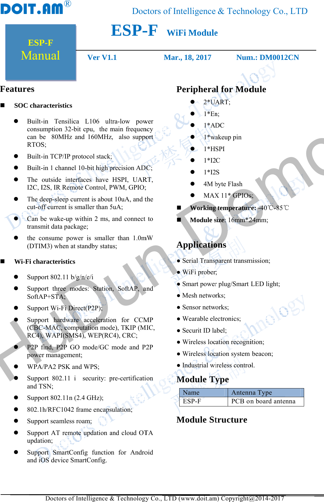
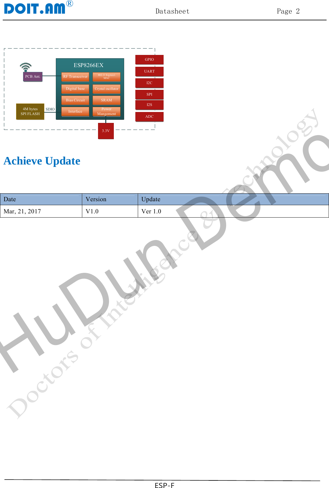
ShenZhen Doctors of Intelligence and Technology
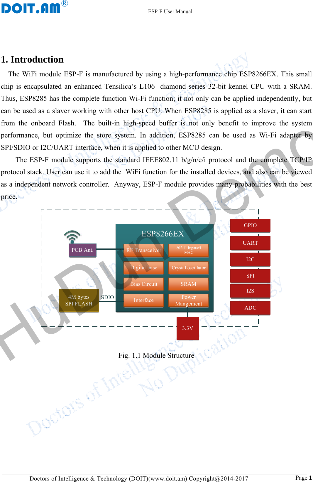
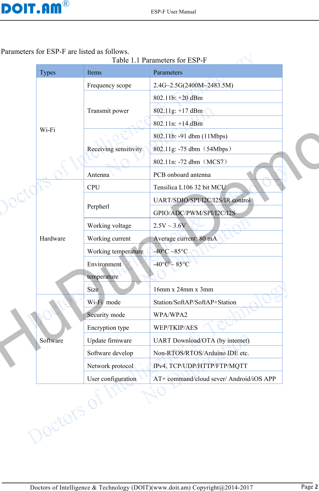
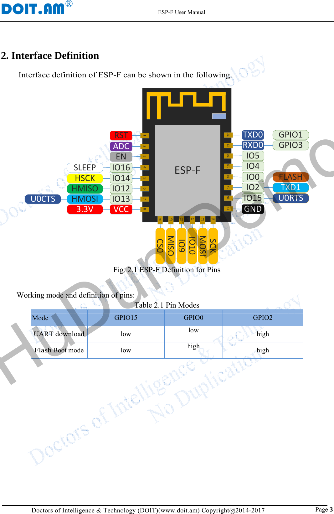
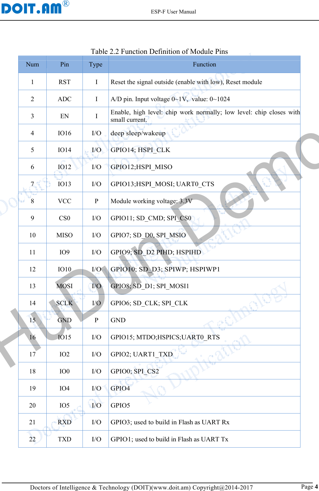
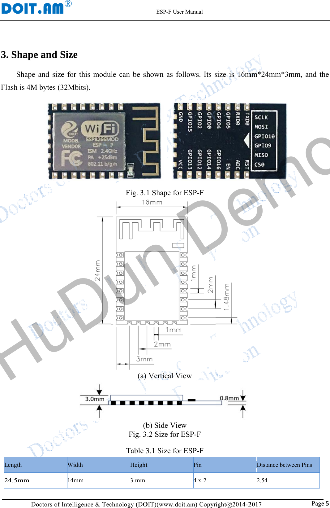
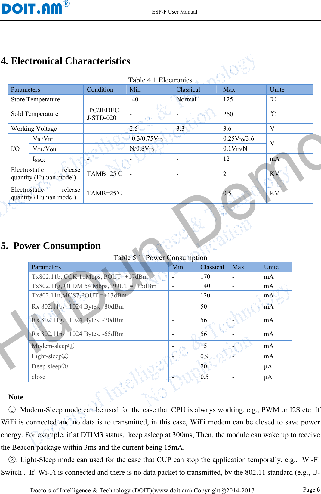
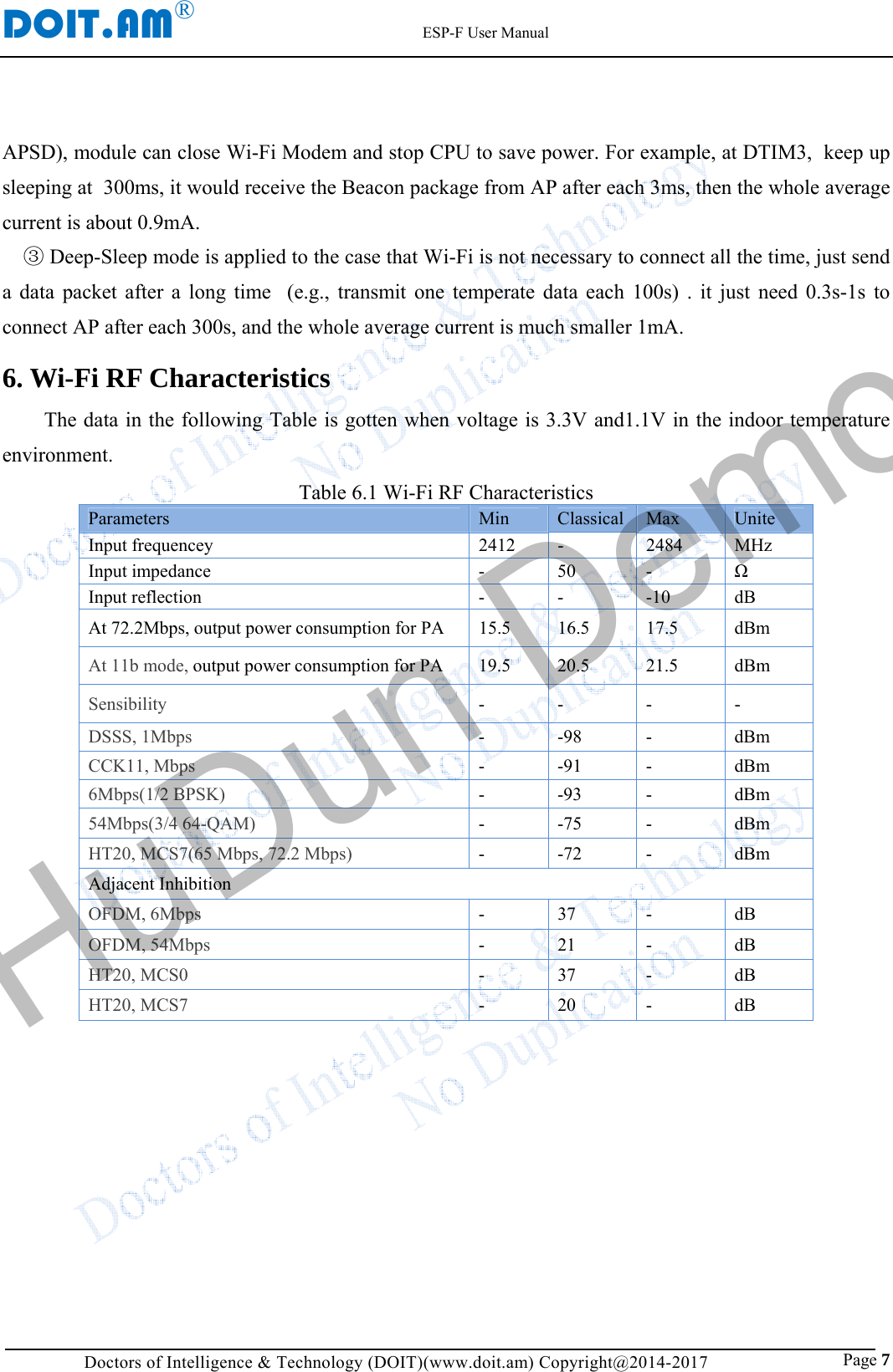
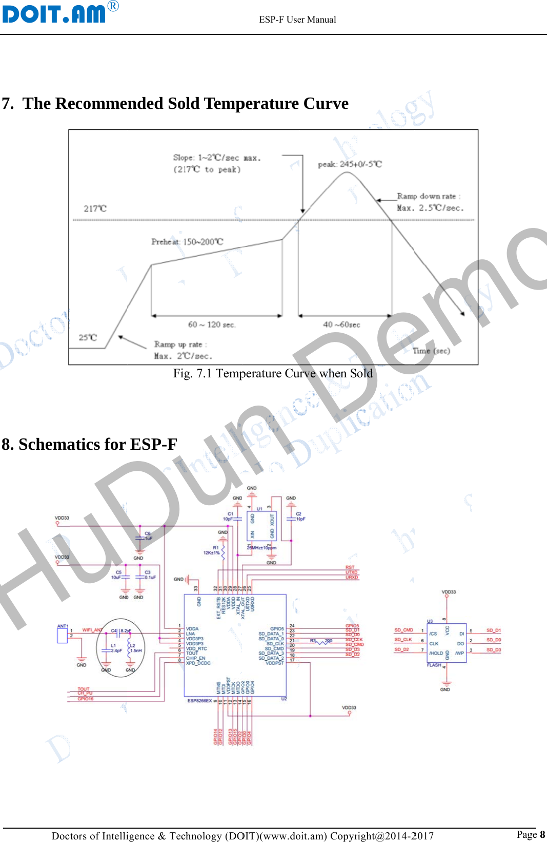
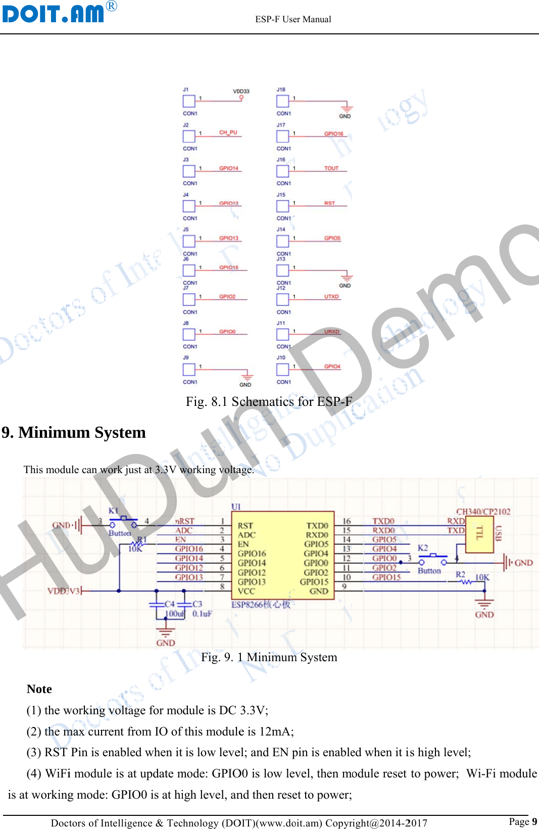
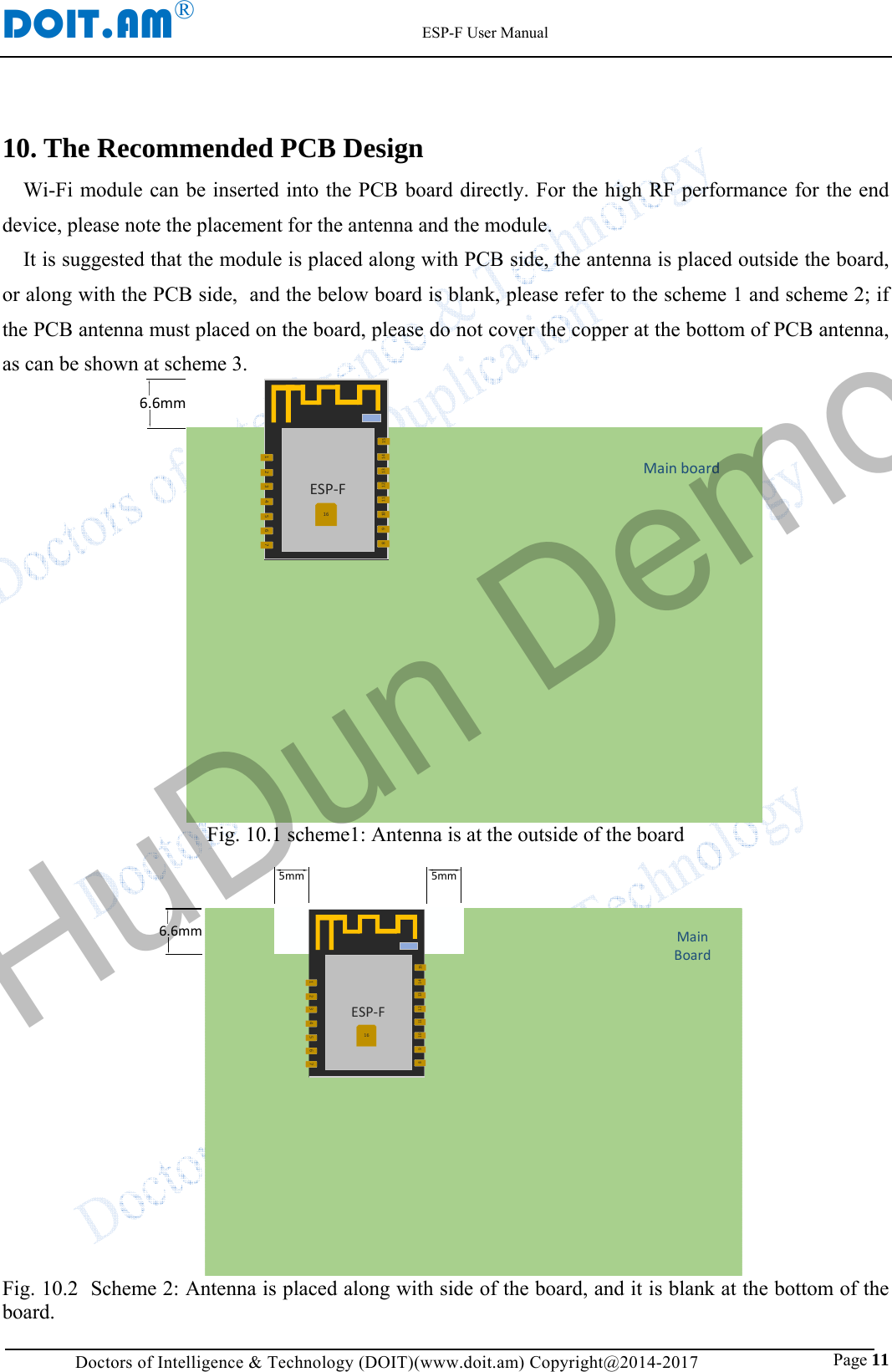
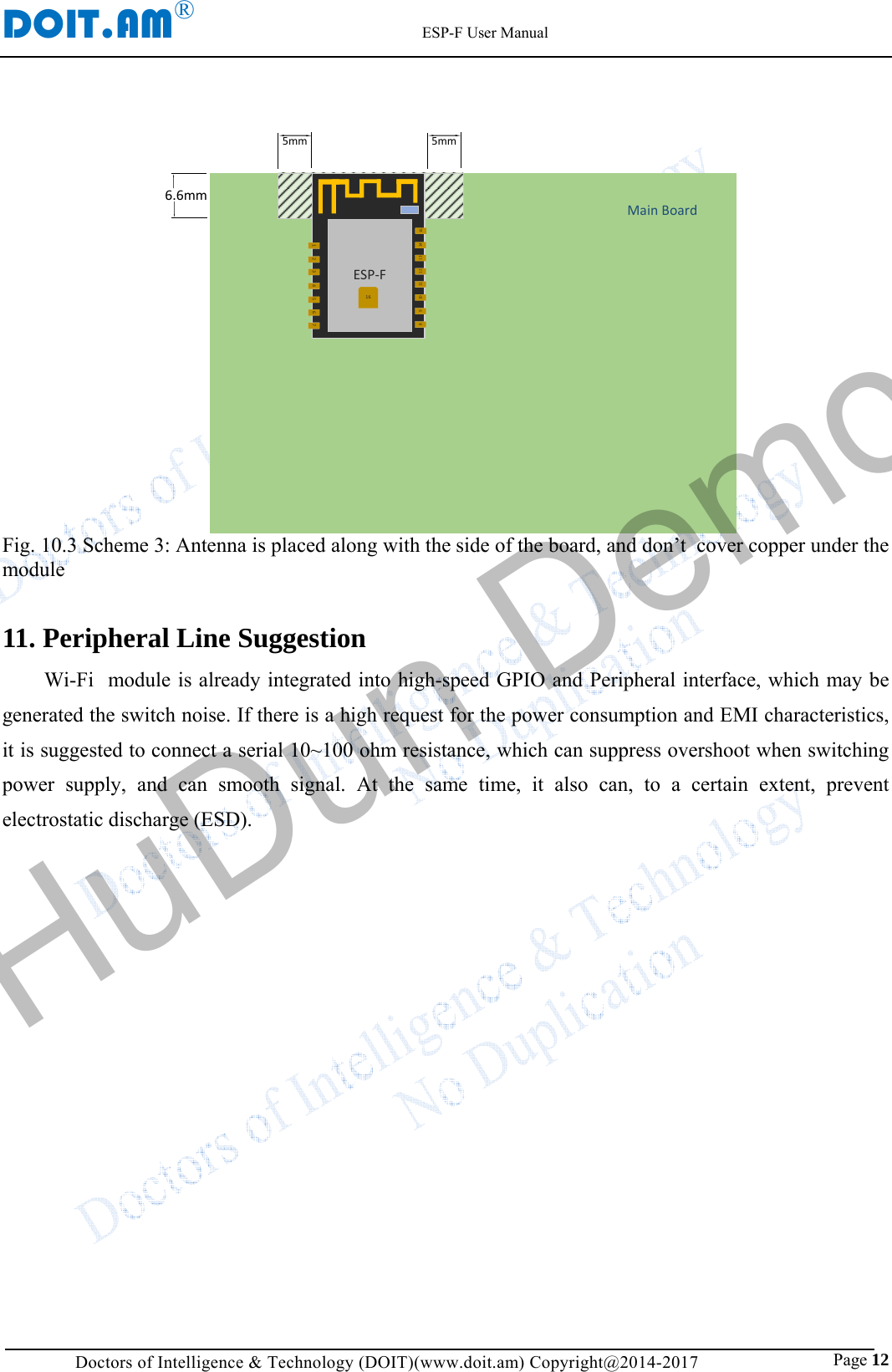
 ESP-F ESP-F WiFi Module User Manual UserManualForESP F doit V1 1

ShenZhen Doctors of Intelligence & Technology Ltd. ESP-F WiFi Module UserManualForESP F doit V1 1

User Manual

DFe  ESPManDOIT.               eatures SOC charBuilt-consucan bRTOSBuilt-Built-TheI2C, IThe dcut-ofCan btransmthe c(DTIMWi-Fi chaSuppoSuppoSoftASuppoSuppo(CBCRC4)P2P fpoweWPASuppoand TSuppo802.1SuppoSuppoupdatSuppoand iOP-Fnual AM®    Doctors of Iracteristics -in Tensilicaumption 32-bbe  80MHz aS; -in TCP/IP pr-in 1 channel outside interI2S, IR Remodeep-sleep cuff current is sbe wake-up wmit data packonsume powM3) when at aracteristics ort 802.11 b/gort three moAP+STA; ort Wi-Fi Dirort hardwareC-MAC, comp), WAPI(SMSfind, P2P GOer managemenA/PA2 PSK anort 802.11 i TSN; ort 802.11n (1h/RFC1042 fort seamless rort AT remottion; ort SmartCoOS device SmVer V1Intelligence &a L106 ultbit cpu,  the mand 160MHzrotocol stack;10-bit high prfaces have ote Control, Purrent is aboutsmaller than 5within 2 ms, kage; wer is smallestandby statug/n/e/i odes: Stationrect(P2P); e acceleratioputation modS4), WEP(RCO mode/GC nt; nd WPS;  security: p2.4 GHz); frame encapsroam;  te updation aonfig functionmartConfig. DocESP-.1& Technologytra-low powmain frequenz,  also suppo; precision ADHSPI, UARPWM, GPIO;t 10uA, and t5uA; and connect er than 1.0mus; n, SoftAP, aon for CCMde), TKIP (MC4), CRC; mode and P2pre-certificatisulation; and cloud OTn for Androctors of Int-F  WiF         Mar.,y Co., LTD (wer ncy ort C; RT, ; the to mW and MP MIC, 2P ion TA oid PA● ● ● ● ● ● ● ● ● ● MMtelligenceFi Module, 18, 2017   www.doit.amPeriphera 2*UA 1*En 1*AD 1*wa 1*H 1*I2 1*I2 4M b MAX Working Module sApplicatioSerial TranspWiFi proberSmart powerMesh netwoSensor netwWearable eleSecurit ID laWireless locWireless locIndustrial wiModule TyName ESP-F Module St& Technoe           Numm) Copyright@al for ModART; n; DC akeup pin SPI C S byte Flash X 11* GPIOsg temperatursize: 16mm*2ons parent transm; r plug/Smart rks; orks; ectronics; abel;  ation recogniation system ireless controype AntennPCB ontructure ology Co.m.: DM0012@2014-2017 dule s; re: -40℃-85℃24mm; mission;   LED light;   ition; beacon;  ol. na Type n board ante, LTD2CN ℃ nna HuDun Demo
DOIT.AM®                      Datasheet                       Page 2 ESP-F ESP8266EX802.11 b/g/n/e/iMACInterfaceSRAMPower MangementRF TransceiverDigital baseCrystal oscillatorBias CircuitPCB Ant.4M bytes SPI FLASHSDIO3.3VGPIOUARTI2CSPIADCI2S Achieve Update   Date  Version  Update Mar, 21, 2017  V1.0  Ver 1.0                     HuDun Demo
DOIT.AM® Doctors of Intelligence & Technology Co. Ltd (www.doit.am) Copyright@2014-2017 Context  Figures ................................................................................................................................... 4Table ...................................................................................................................................... 41. Introduction ....................................................................................................................... 12. Interface Definition ........................................................................................................... 33. Shape and Size ................................................................................................................... 54. Electronical Characteristics ............................................................................................... 6 5.  Power Consumption ......................................................................................................... 6 6. Wi-Fi RF Characteristics ................................................................................................... 7 7.  The Recommended Sold Temperature Curve .................................................................. 88. Schematics for ESP-F ........................................................................................................ 89. Minimum System .............................................................................................................. 910. The Recommended PCB Design ................................................................................... 1111. Peripheral Line Suggestion ........................................................................................... 12Appendix. ............................................................................................................................ 13   HuDun Demo
DOIT.AM® Doctors of Intelligence & Technology Co. Ltd (www.doit.am) Copyright@2014-2017 Figures  Fig. 1.1 Module Structure ..................................................................................................................................................... 1 Fig. 2.1 ESP-F Definition for Pins ........................................................................................................................................ 3 Fig. 3.1 Shape for ESP-F ....................................................................................................................................................... 5Fig. 3.2 Size for ESP-F ......................................................................................................................................................... 5 Fig. 7.1 Temperature Curve when Sold ................................................................................................................................ 8 Fig. 9. 1 Minimum System .................................................................................................................................................... 9 Fig. 10.1 scheme1: Antenna is at the outside of the board .................................................................................................. 11Fig. 10.2  Scheme 2: Antenna is placed along with side of the board, and it is blank at the bottom of the board. ............. 11Fig. 10.3 Scheme 3: Antenna is placed along with the side of the board, and don’t  cover copper under the module........ 12Table Table 1.1 Parameters for ESP-F ............................................................................................................................................ 2 Table 2.1 Pin Modes ............................................................................................................................................................. 3Table 2.2 Function Definition of Module Pins ...................................................................................................................... 4 Table 3.1 Size for ESP-F ....................................................................................................................................................... 5 Table 4.1 Electronics ............................................................................................................................................................. 6 Table 5.1  Power Consumption ............................................................................................................................................. 6 Table 6.1 Wi-Fi RF Characteristics ....................................................................................................................................... 7     HuDun Demo
DOIT.AM®                                                          ESP-F User Manual Doctors of Intelligence & Technology (DOIT)(www.doit.am) Copyright@2014-2017                               Page 1 1. Introduction The WiFi module ESP-F is manufactured by using a high-performance chip ESP8266EX. This small chip is encapsulated an enhanced Tensilica’s L106  diamond series 32-bit kennel CPU with a SRAM. Thus, ESP8285 has the complete function Wi-Fi function; it not only can be applied independently, but can be used as a slaver working with other host CPU. When ESP8285 is applied as a slaver, it can start from the onboard Flash.  The built-in high-speed buffer is not only benefit to improve the system performance, but optimize the store system. In addition, ESP8285 can be used as Wi-Fi adapter by SPI/SDIO or I2C/UART interface, when it is applied to other MCU design. The ESP-F module supports the standard IEEE802.11 b/g/n/e/i protocol and the complete TCP/IP protocol stack. User can use it to add the  WiFi function for the installed devices, and also can be viewed as a independent network controller.  Anyway, ESP-F module provides many probabilities with the best price.  ESP8266EX802.11 b/g/n/e/iMACInterfaceSRAMPower MangementRF TransceiverDigital base Crystal oscillatorBias CircuitPCB Ant.4M bytes SPI FLASHSDIO3.3VGPIOUARTI2CSPIADCI2S  Fig. 1.1 Module Structure HuDun Demo
DOIT.AM®                                                          ESP-F User Manual Doctors of Intelligence & Technology (DOIT)(www.doit.am) Copyright@2014-2017                               Page 2 Parameters for ESP-F are listed as follows. Table 1.1 Parameters for ESP-F Types  Items  Parameters Wi-Fi Frequency scope  2.4G~2.5G(2400M~2483.5M) Transmit power 802.11b: +20 dBm 802.11g: +17 dBm 802.11n: +14 dBm Receiving sensitivity 802.11b: -91 dbm (11Mbps) 802.11g: -75 dbm(54Mbps) 802.11n: -72 dbm(MCS7) Antenna PCB onboard antenna Hardware CPU  Tensilica L106 32 bit MCU Perpherl UART/SDIO/SPI/I2C/I2S/IR control GPIO/ADC/PWM/SPI/I2C/I2S Working voltage  2.5V ~ 3.6V Working current  Average current: 80 mA Working temperature  -40°C ~85°C Environment temperature -40°C ~ 85°C Size  16mm x 24mm x 3mm Software Wi-Fi  mode  Station/SoftAP/SoftAP+Station Security mode  WPA/WPA2 Encryption type  WEP/TKIP/AES Update firmware  UART Download/OTA (by internet) Software develop  Non-RTOS/RTOS/Arduino IDE etc. Network protocol  IPv4, TCP/UDP/HTTP/FTP/MQTT User configuration  AT+ command/cloud sever/ Android/iOS APP        HuDun Demo
DOIT.AM®                                                          ESP-F User Manual Doctors of Intelligence & Technology (DOIT)(www.doit.am) Copyright@2014-2017                               Page 3 2. Interface Definition   Interface definition of ESP-F can be shown in the following.  1 2 43 5 6 7 815 16 1817 19 20 21 22910 1211 13 14ESP-FRSTADCENIO14IO12IO13VCCIO16TXD0RXD0IO5IO0IO2IO15GNDIO4GPIO1GPIO3FLASHTXD1U0RTSHSCKHMISOHMOSI3.3VU0CTSSLEEPCS0MISOIO9IO10MOSISCK Fig. 2.1 ESP-F Definition for Pins  Working mode and definition of pins: Table 2.1 Pin Modes Mode  GPIO15  GPIO0  GPIO2 UART download low low  high Flash Boot mode low high  high HuDun Demo
DOIT.AM®                                                          ESP-F User Manual Doctors of Intelligence & Technology (DOIT)(www.doit.am) Copyright@2014-2017                               Page 4 Table 2.2 Function Definition of Module Pins Num  Pin  Type  Function 1 RST I  Reset the signal outside (enable with low), Reset module 2  ADC  I  A/D pin. Input voltage 0~1V,  value: 0~1024 3 EN I  Enable, high level: chip work normally; low level: chip closes with small current. 4 IO16 I/O deep sleep/wakeup 5 IO14 I/O GPIO14; HSPI_CLK 6 IO12 I/O GPIO12;HSPI_MISO 7 IO13 I/O GPIO13;HSPI_MOSI; UART0_CTS 8  VCC  P  Module working voltage: 3.3V 9 CS0 I/O  GPIO11; SD_CMD; SPI_CS0 10 MISO I/O  GPIO7; SD_D0, SPI_MSIO 11 IO9 I/O  GPIO9; SD_D2 PIHD; HSPIHD 12 IO10 I/O GPIO10; SD_D3; SPIWP; HSPIWP1 13 MOSI I/O GPIO8; SD_D1; SPI_MOSI1 14 SCLK I/O  GPIO6; SD_CLK; SPI_CLK 15 GND P GND 16 IO15 I/O GPIO15; MTDO;HSPICS;UART0_RTS 17 IO2 I/O GPIO2; UART1_TXD 18 IO0 I/O GPIO0; SPI_CS2 19 IO4 I/O GPIO4 20 IO5 I/O GPIO5 21 RXD I/O  GPIO3; used to build in Flash as UART Rx 22 TXD I/O GPIO1; used to build in Flash as UART Tx     HuDun Demo
D3. Fla   L2DOIT.Doct. Shape aShape anash is 4M b Length 4.5mm AM®    tors of Intelliand Sizend size for bytes (32MbWid14m                        igence & Tece this modulbits). dth mm                         chnology (DOle can be shFig. 3.(a)(bFig. 3Table 3Height3 mm      ESP-F UseOIT)(www.dohown as fo    1 Shape for Vertical Vb) Side Vie3.2 Size for 3.1 Size fort  er Manual oit.am) Copyrollows. Its sr ESP-F iew w ESP-F r ESP-F Pin 4 x 2 right@2014-2size is 16m 2017               mm*24mm* Distance be2.54                 Pag3mm, and  etween Pins ge 5 the HuDun Demo
DOIT.AM®                                                          ESP-F User Manual Doctors of Intelligence & Technology (DOIT)(www.doit.am) Copyright@2014-2017                               Page 6 4. Electronical Characteristics  Table 4.1 Electronics Parameters  Condition  Min  Classical  Max  Unite Store Temperature  -  -40  Normal  125  ℃ Sold Temperature  IPC/JEDEC J-STD-020  - - 260 ℃ Working Voltage -  2.5 3.3 3.6 V I/O VIL/VIH -  -0.3/0.75VIO -  0.25VIO/3.6  V VOL/VOH -  N/0.8VIO -  0.1VIO/N IMAX - - - 12 mA Electrostatic release quantity (Human model)  TAMB=25℃ - - 2 KV Electrostatic release quantity (Human model)  TAMB=25℃ - - 0.5 KV     5.  Power Consumption Table 5.1  Power Consumption Parameters  Min  Classical Max  Unite Tx802.11b, CCK 11Mbps, POUT=+17dBm -  170 -  mA Tx802.11g, OFDM 54 Mbps, POUT =+15dBm -  140  -  mA Tx802.11n,MCS7,POUT =+13dBm - 120 - mA Rx 802.11b,1024 Bytes, -80dBm - 50 -  mA Rx 802.11g,1024 Bytes, -70dBm  - 56 -  mA Rx 802.11n,1024 Bytes, -65dBm  - 56 -  mA Modem-sleep① - 15 -  mA Light-sleep② - 0.9 -  mA Deep-sleep③ - 20 -  μA close  - 0.5 -  μA  Note ①: Modem-Sleep mode can be used for the case that CPU is always working, e.g., PWM or I2S etc. If WiFi is connected and no data is to transmitted, in this case, WiFi modem can be closed to save power energy. For example, if at DTIM3 status,  keep asleep at 300ms, Then, the module can wake up to receive the Beacon package within 3ms and the current being 15mA. ②: Light-Sleep mode can used for the case that CUP can stop the application temporally, e.g.,  Wi-Fi Switch .  If  Wi-Fi is connected and there is no data packet to transmitted, by the 802.11 standard (e.g., U-HuDun Demo
DOIT.AM®                                                          ESP-F User Manual Doctors of Intelligence & Technology (DOIT)(www.doit.am) Copyright@2014-2017                               Page 7 APSD), module can close Wi-Fi Modem and stop CPU to save power. For example, at DTIM3,  keep up sleeping at  300ms, it would receive the Beacon package from AP after each 3ms, then the whole average current is about 0.9mA. ③ Deep-Sleep mode is applied to the case that Wi-Fi is not necessary to connect all the time, just send a data packet after a long time  (e.g., transmit one temperate data each 100s) . it just need 0.3s-1s to connect AP after each 300s, and the whole average current is much smaller 1mA. 6. Wi-Fi RF Characteristics The data in the following Table is gotten when voltage is 3.3V and1.1V in the indoor temperature environment.   Table 6.1 Wi-Fi RF Characteristics Parameters  Min  Classical Max  Unite Input frequencey  2412  -  2484  MHz Input impedance  -  50  -  Ω Input reflection  -  -  -10  dB At 72.2Mbps, output power consumption for PA  15.5  16.5  17.5  dBm At 11b mode, output power consumption for PA 19.5 20.5  21.5  dBm Sensibility  - -  -  - DSSS, 1Mbps  - -98 -  dBm CCK11, Mbps  - -91 -  dBm 6Mbps(1/2 BPSK)  - -93 -  dBm 54Mbps(3/4 64-QAM)  - -75 -  dBm HT20, MCS7(65 Mbps, 72.2 Mbps)  - -72 -  dBm Adjacent Inhibition OFDM, 6Mbps  - 37 -  dB OFDM, 54Mbps  - 21 -  dB HT20, MCS0  - 37 -  dB HT20, MCS7  - 20 -  dB    HuDun Demo
D7.    8. DOIT.Doct.  The Re. SchemaAM®    tors of Intelliecommeatics for                         igence & Tecnded SoFigESP-F                         chnology (DOld Tempg. 7.1 Temp      ESP-F UseOIT)(www.doperature perature Curer Manual oit.am) CopyrCurverve when Sright@2014-2old 2017                               Pag  ge 8 HuDun Demo
D9.  isDOIT.Doct. MinimuThis moduNote (1) the w(2) the m(3) RST (4) WiFis at workingAM®    tors of Intellium Systeule can work jworking voltmax current Pin is enabi module is g mode: GP                        igence & Tecem just at 3.3V wtage for mofrom IO of bled when itat update mPIO0 is at hi                        chnology (DOFig. 8.1 Sworking voltaFig. 9. 1dule is DC fthis moduleis low levemode: GPIOigh level, an      ESP-F UseOIT)(www.dochematics age. 1 Minimum3.3V; e is 12mA;el; and EN pO0 is low levnd then reseer Manual oit.am) Copyrfor ESP-Fm System pin is enablevel, then met to power;right@2014-2  ed when it iodule reset  2017               is high levelto power;                  Pagl; Wi-Fi modge 9  dule HuDun Demo
DOIT.AM®                                                          ESP-F User Manual Doctors of Intelligence & Technology (DOIT)(www.doit.am) Copyright@2014-2017                               Page 10 (5) Wi-Fi module is connected to RXD of the other MCU, and TXD is connected to RXD of the other MCU.   HuDun Demo
DOIT.AM®                                                          ESP-F User Manual Doctors of Intelligence & Technology (DOIT)(www.doit.am) Copyright@2014-2017                               Page 11 10. The Recommended PCB Design Wi-Fi module can be inserted into the PCB board directly. For the high RF performance for the end device, please note the placement for the antenna and the module.      It is suggested that the module is placed along with PCB side, the antenna is placed outside the board, or along with the PCB side,  and the below board is blank, please refer to the scheme 1 and scheme 2; if the PCB antenna must placed on the board, please do not cover the copper at the bottom of PCB antenna, as can be shown at scheme 3. Mainboard6.6mm810911 12 13 14ESP-F15161 2 43 5 6 7 Fig. 10.1 scheme1: Antenna is at the outside of the board  MainBoard5mm6.6mm5mm810911 12 13 14ESP-F15161 2 43 5 6 7 Fig. 10.2  Scheme 2: Antenna is placed along with side of the board, and it is blank at the bottom of the board.  HuDun Demo
DOIT.AM®                                                          ESP-F User Manual Doctors of Intelligence & Technology (DOIT)(www.doit.am) Copyright@2014-2017                               Page 12 MainBoard5mm6.6mm5mm810911 12 13 14ESP-F15161 2 43 5 6 7 Fig. 10.3 Scheme 3: Antenna is placed along with the side of the board, and don’t  cover copper under the module  11. Peripheral Line Suggestion Wi-Fi  module is already integrated into high-speed GPIO and Peripheral interface, which may be generated the switch noise. If there is a high request for the power consumption and EMI characteristics, it is suggested to connect a serial 10~100 ohm resistance, which can suppress overshoot when switching power supply, and can smooth signal. At the same time, it also can, to a certain extent, prevent electrostatic discharge (ESD).   HuDun Demo
DDnomepreresanlicTAtheDOIT.DoctoDisclaimThe informotice. Documentserchantabiliesented by sponsibilityny patent ricensing, wheThe Wi-Fi aAll the mene property oAM®ors of Intelligmer anmation in this are proviity, suitableany propoy, including ights. This ether expreslliance markntioned branof their respgence & Technd Cois article, inided by the for any pasal, specifithe use of tdocument ss or implieks shall be nd names, tpective ownehnology (DOIopyrighncluding thehe current varticular purcation, or sthe informain this, byed license.owned by thtrademarks ers, and herNoticBemanuTechncontereminDoctotry thmanuis comthis mto pro ESP-F UseIT)(www.doitht Note URL for version wirpose or nosample menation within y estoppel he Wi-Fi aland registereby declarece ecause of tual may hnology Cents of thinders. Thors of Inteheir best toual, but it mpletely manual, anovide any er Manual t.am) Copyrigtice reference, ithout any on-infringemntioned elsethis documor otherwilliance. ered trademe. the produchange. Co., LTD s manual his manuaelligence &o provide does not right and nd informexpress oght@2014-20if there is aguarantee ment guaranewhere. Thment produceise, grant aarks presenct update Doctors Keeps thein the absal is use& Technothe accuraensure thanational, mation andor implied 017  any change,responsibilntees, and ahis documened by the inany intellecnted in this or other rof Intee right tosence of aed only aology Co., ate informat the manall the std advice dguarantee Page without prlity, includiany guarantent has no anfringementctual propedocument reasons, thelligence change tany notice as a guidLTD woumation in thnual contetatements do not mees. e 14 rior ing ees any t of erty are his & the or de, uld his ent in ean HuDun Demo
This device complies with part 15 of the FCC Rules. Operation is subject to the following two conditions:(1) this device may not cause harmful interference, and (2) this device must accept any interference received,including interference that may cause undesired operation.Any changes or modifications not expressly approved by the party responsible for compliancecould void the user's authority to operate the equipment.NOTE: This equipment has been tested and found to comply with the limits for a Class B digital device,pursuant to Part 15 of the FCC Rules. These limits are designed to provide reasonable protection againstharmful interference in a residential installation. This equipment generates, uses and can radiate radio frequencyenergy and, if not installed and used in accordance with the instructions, may cause harmful interference toradio communications. However, there is no guarantee that interference will not occur in a particularinstallation.If this equipment does cause harmful interference to radio or television reception,which can be determined by turning the equipment off and on, the user is encouraged to try to correct theinterference by one or more of the following measures:-- Reorient or relocate the receiving antenna.-- Increase the separation between the equipment and receiver.-- Connect the equipment into an outlet on a circuit differentfrom that to which the receiver is connected.-- Consult the dealer or an experienced radio/TV technician for help.The device has been evaluated to meet general RF exposure requirement. The device can be used in portable exposure condition without restriction.FCC ID: 2AL3B-ESP-F

Navigation menu