ShenZhen Foscam Intelligent Technology FI9821W Indoor HD Pan/Tilt Wireless IP Camera User Manual 1
ShenZhen Foscam Intelligent Technology Co., Ltd. Indoor HD Pan/Tilt Wireless IP Camera 1
UserManual.wiki
>
ShenZhen Foscam Intelligent Technology
>
FI9821W User Manual
User Manual
Navigation menu
Upload a User Manual
Namespaces
Wiki Guide
HTML
PDF
Info
Views
User Manual
Discussion / Help
Navigation
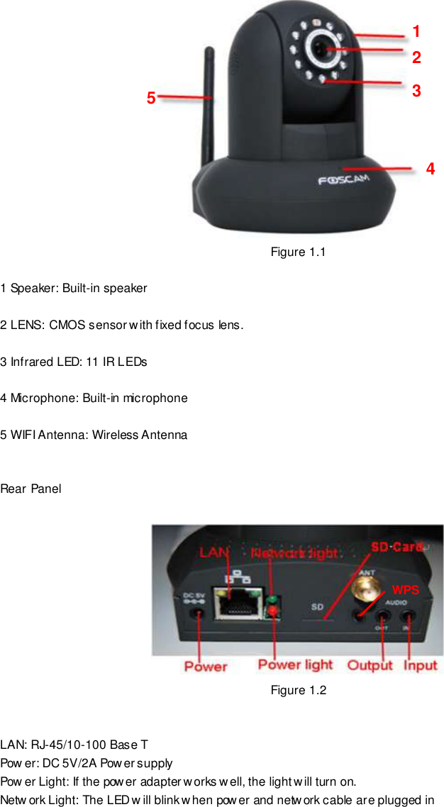
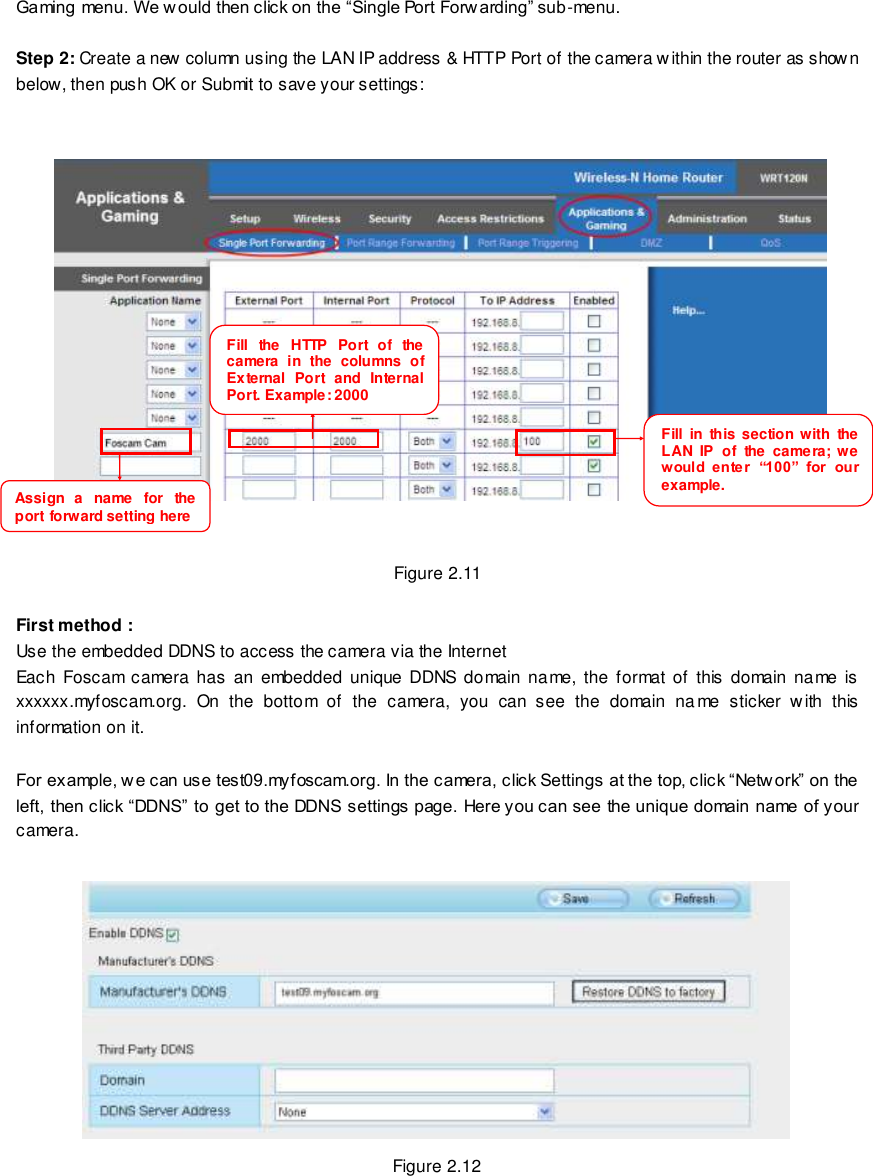
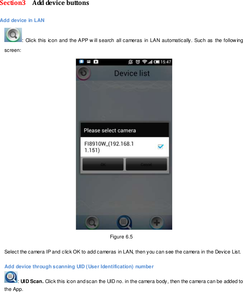
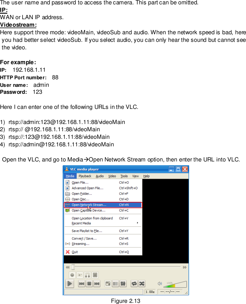
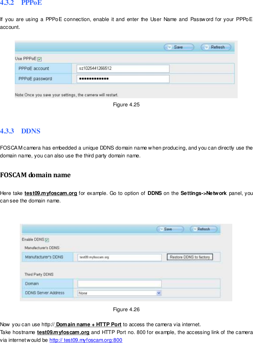
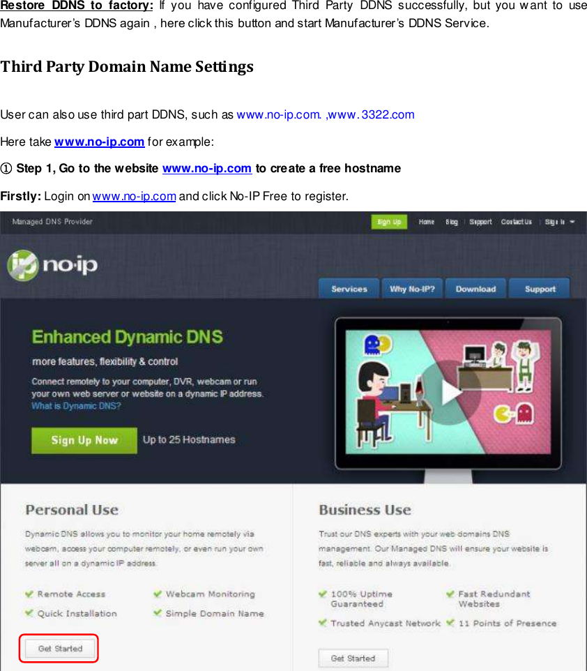
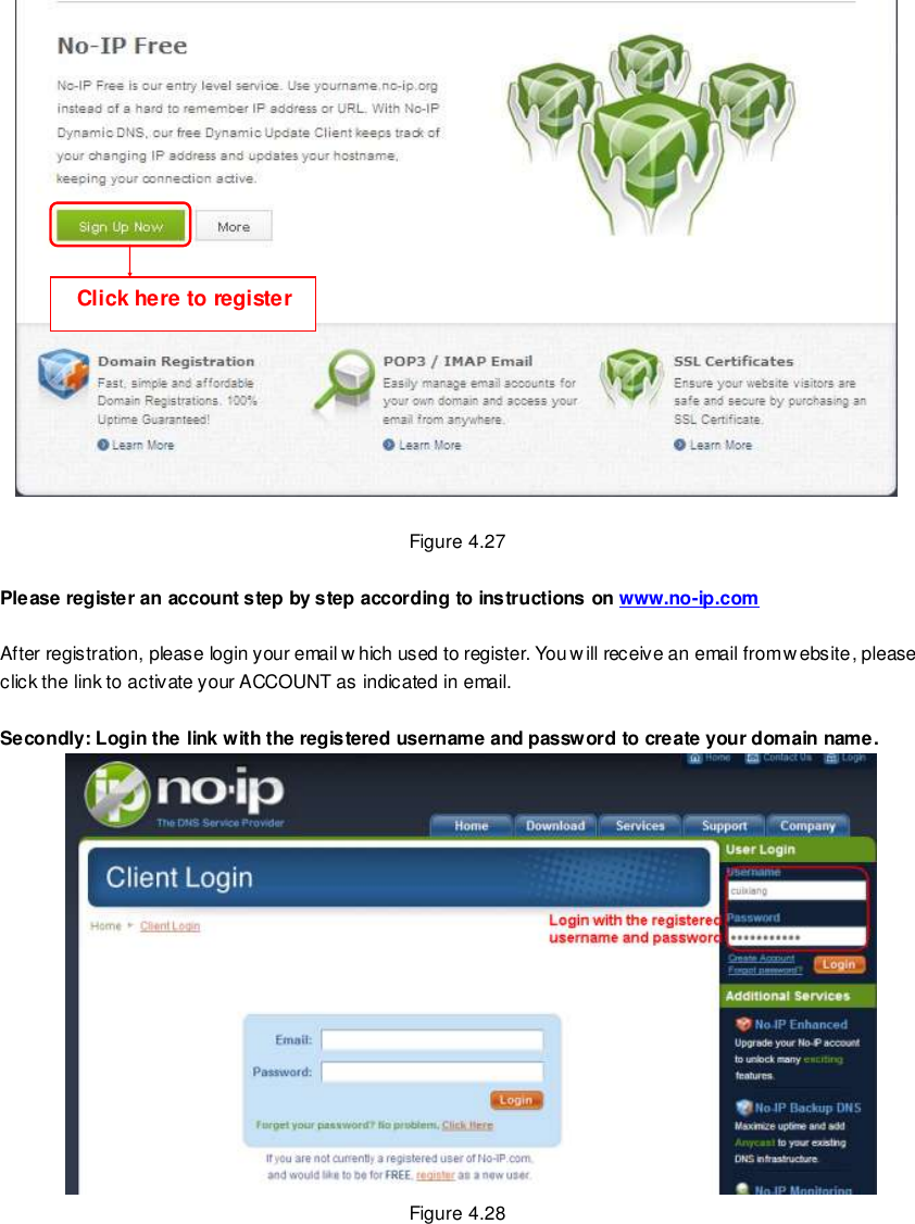
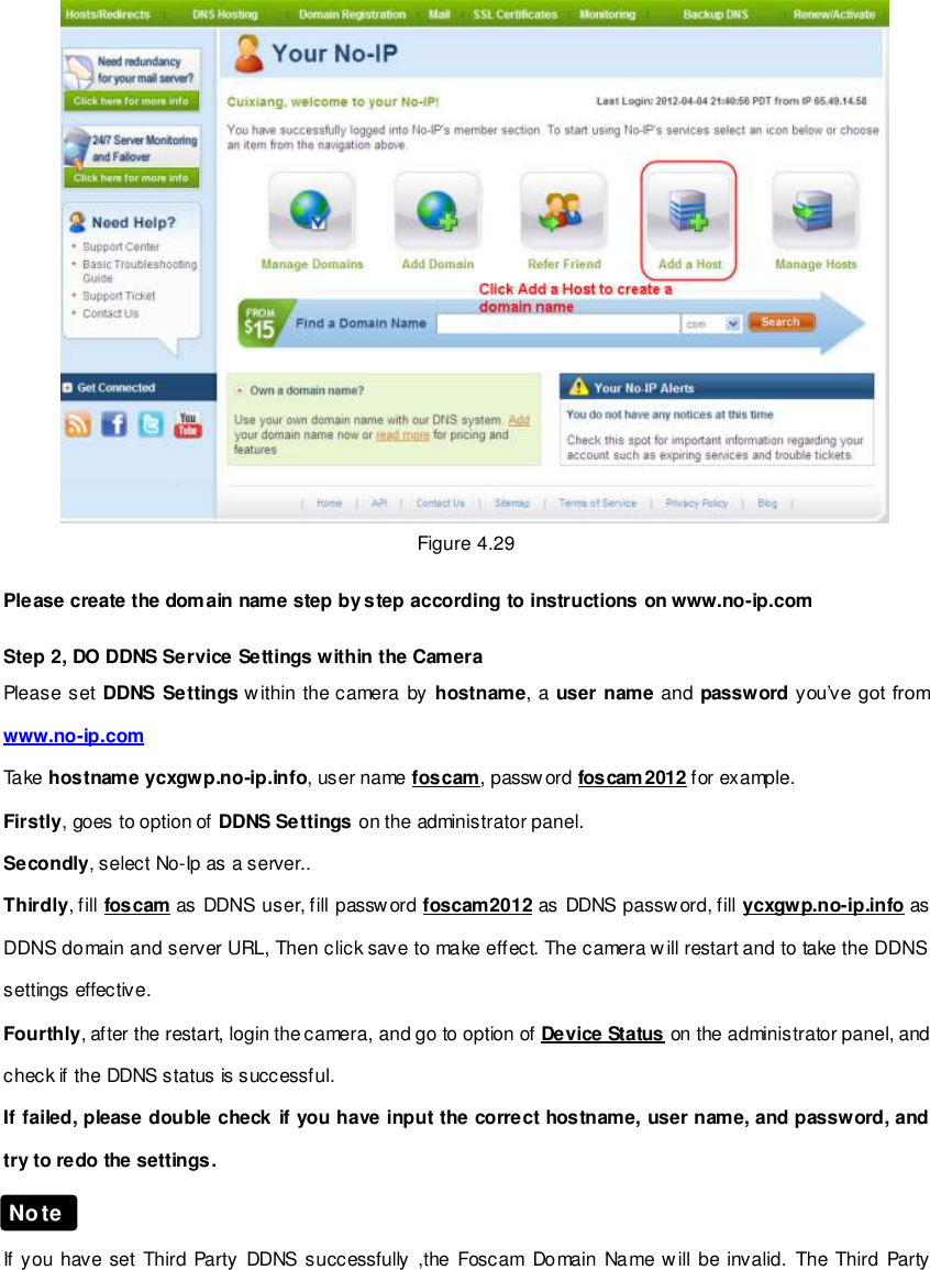
![14 wwwwwwww..ffoossccaamm..ccoomm SShheennzzhheenn FFoossccaamm IInntteelllliiggeenntt TTeecchhnnoollooggyy CCoo..,, LLiimmiitteedd TTeell:: 8866 775555 22667744 55666688 FFaaxx:: 8866 775555 22667744 55116688 14 Now you can use “http://Domain name + HTTP Port” to access the camera via the Internet. Take hostname test09.myfoscam.org and HTTP Port of 2000 for example, the URL link to access the camera via the Internet would be http:// test09.myfoscam.org:2000. Second method : Use the Third party DDNS to access the camera via the Internet Step 1 Please go to the third party DDNS website(such as www.no-ip.com) to create a free hostname. Step 2 DO DDNS Service Settings within the Camera Please set DDNS Settings w ithin the camera by hostname, a user name and password you’ve got from www.no-ip.com Take hostname ycxgwp.no-ip.info, user name foscam, password foscam2012 for example. Firstly, goes to option of DDNS Settings on the administrator panel. Secondly, select No-Ip as a server. Thirdly, fill foscam as DDNS user, fill password foscam2012 as DDNS password, fill ycxgwp.no-ip.info as DDNS domain and server URL, Then click save to make effect. The camera will restart and to take the DDNS settings effective. Fourthly, after the restart, login the camera, and go to option of Device Status on the administrator panel, and check if the DDNS status is successful. If failed, please double check if you have input the correct hostname, user name, and password, and try to redo the settings. If you have set Third Party DDNS successfully ,the Foscam Domain Name will be invalid. The Third Party DDNS and the Foscam Domain Name cannot w ork at the same time, the last time you configured will take effect. 2.3 Using the VLC player This camera supports RTSP streaming, here you can view the camera using VLC player. RTSP URL rtsp:// [user name][:password]@IP:HTTP port number/videosream The part in the square brackets may be omitted. user name & password: Note](https://usermanual.wiki/ShenZhen-Foscam-Intelligent-Technology/FI9821W/User-Guide-2028448-Page-15.png)
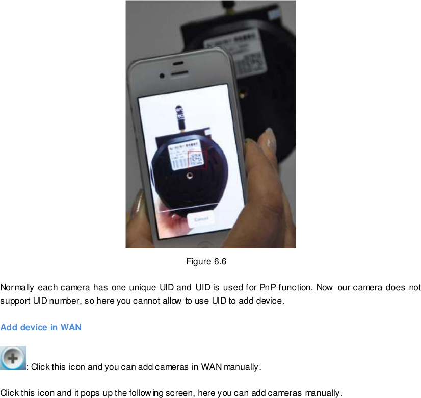
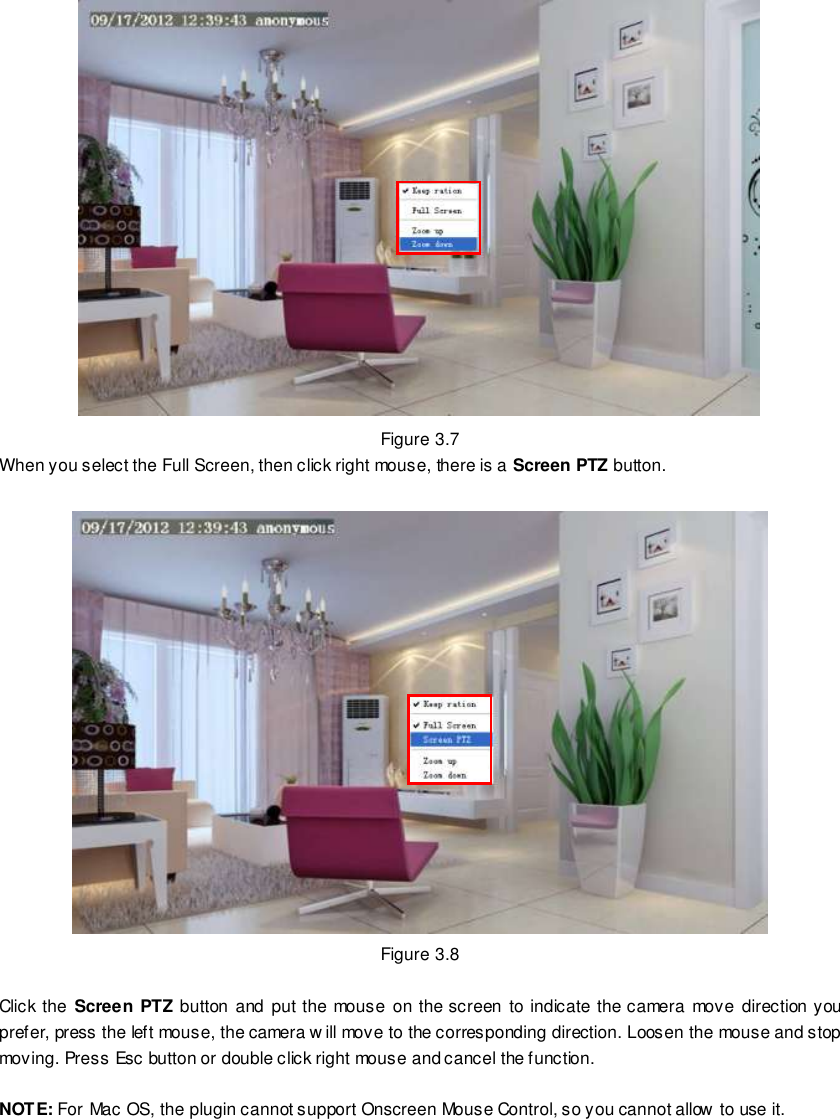
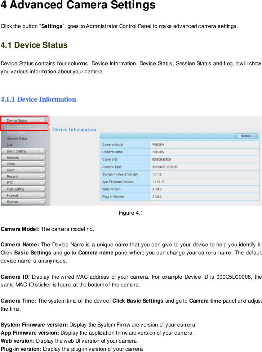
![26 wwwwwwww..ffoossccaamm..ccoomm SShheennzzhheenn FFoossccaamm IInntteelllliiggeenntt TTeecchhnnoollooggyy CCoo..,, LLiimmiitteedd TTeell:: 8866 775555 22667744 55666688 FFaaxx:: 8866 775555 22667744 55116688 26 Onscreen Mouse Control Right click the mouse and you can adjust the screen ration, full screen and Zoom up. Figure 3.6 Keep ration: Select it and the camera w ill adjust the size of live window based on the the computer monitor automatically. Sometimes there is a black border around the video, please select Keep ration to get a better visual quality . Full Screen: Select it and Click it to make full-screen, press ESC and exit full-screen. Zoom up: First Method: Here is a convenient and fast solution to Zoom up/down screen by Clicking Video Screen and adjusting Mouse pulley, or by press the CTRL key and click the mouse left button. Second Method: Click it and the live view w ill be digital zoomed up, then click Zoom Dow n and the live view back to original size. 批注 [A1]:](https://usermanual.wiki/ShenZhen-Foscam-Intelligent-Technology/FI9821W/User-Guide-2028448-Page-27.png)
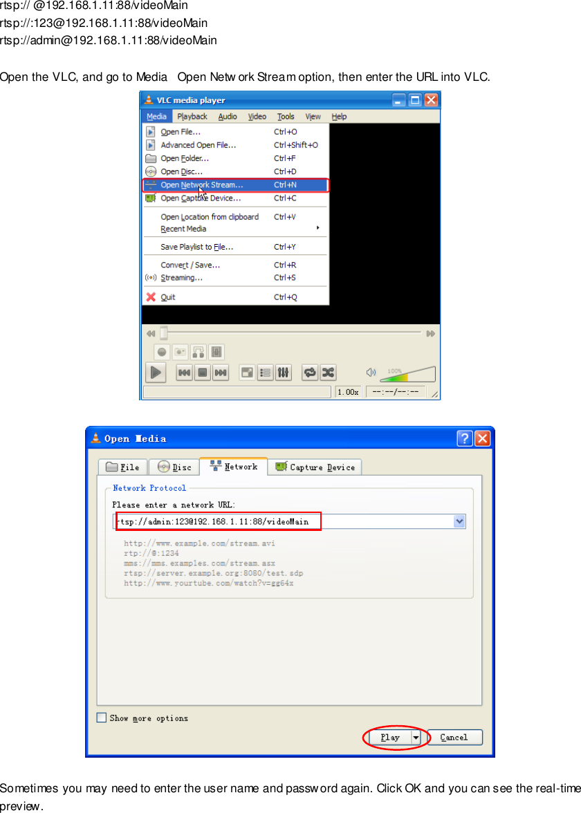
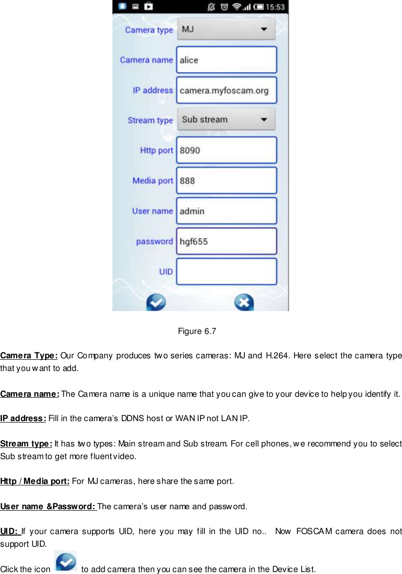
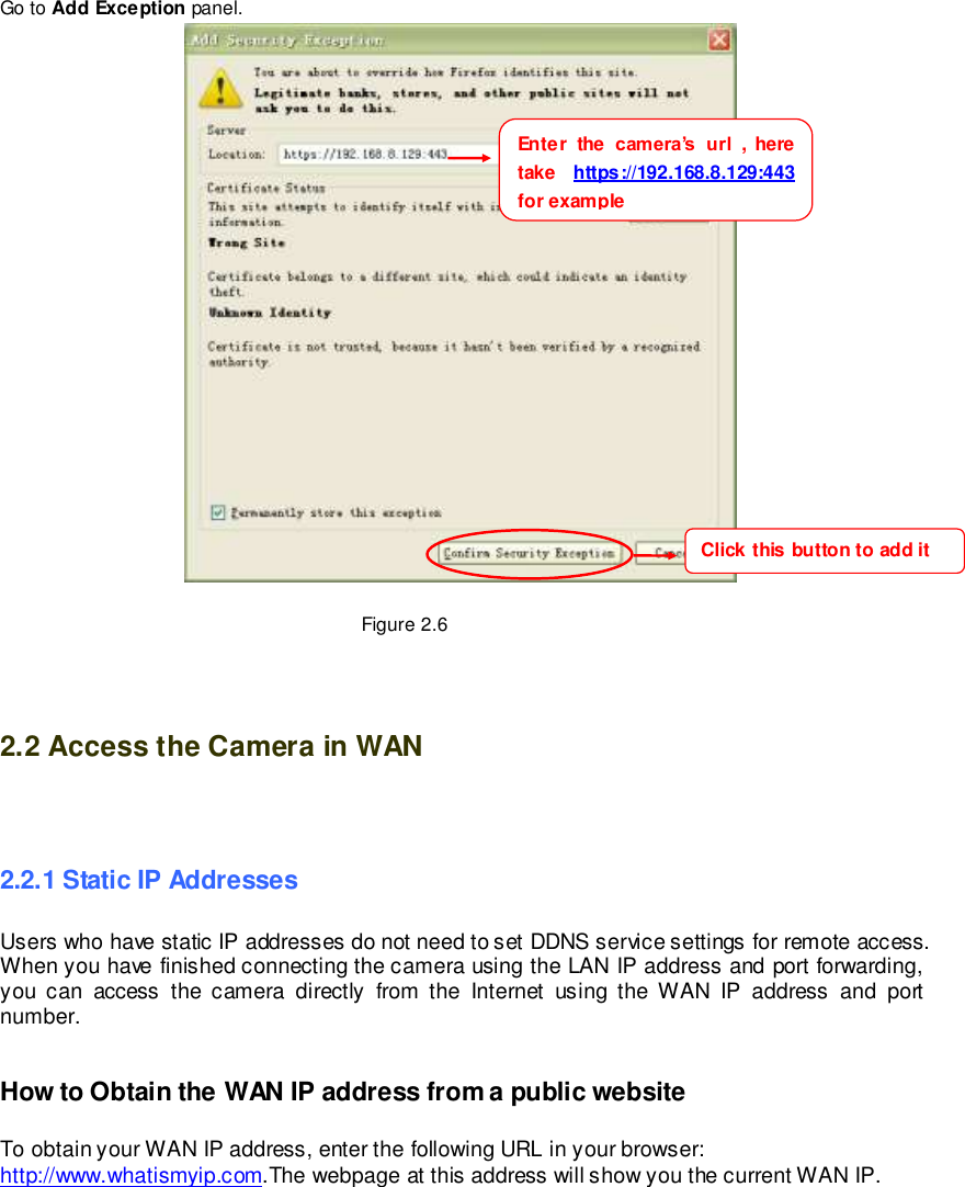
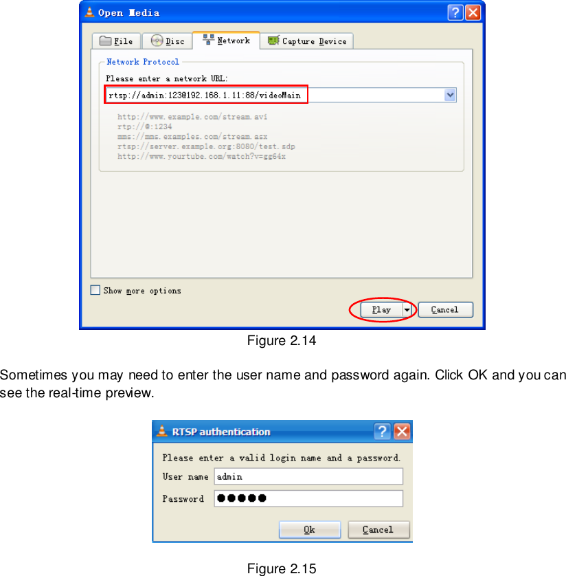
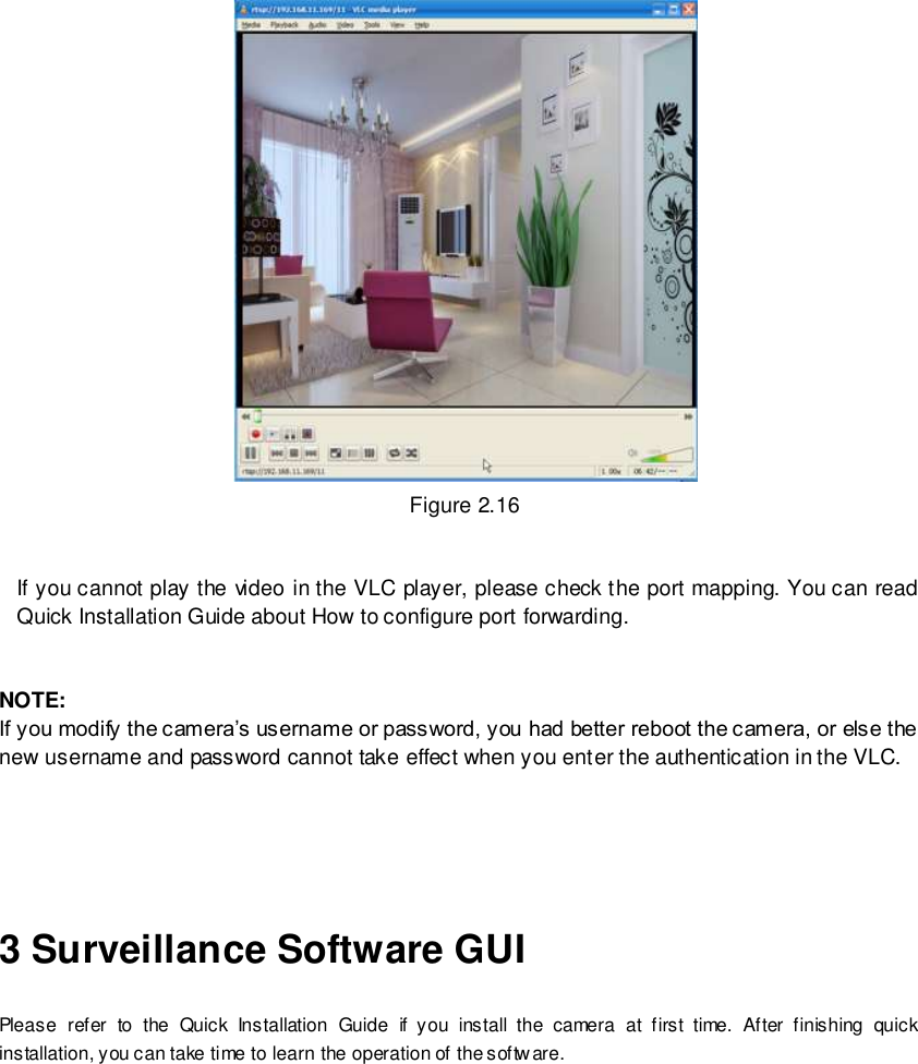
![56 wwwwwwww..ffoossccaamm..ccoomm SShheennzzhheenn FFoossccaamm IInntteelllliiggeenntt TTeecchhnnoollooggyy CCoo..,, LLiimmiitteedd TTeell:: 8866 775555 22667744 55666688 FFaaxx:: 8866 775555 22667744 55116688 56 Go to Add Exception panel. RTSP function RTSP URL rtsp:// [user name][:password]@IP:HTTP port number/videosream The part in the square brackets may be omitted. user name & password: The user name and password to access the camera. This part can be omitted. IP: WAN or LAN IP address. Videostream: Here support three mode: videoMain, videoSub and audio. When the network speed is bad, here you had better select videoSub. If you select audio, you can only hear the sound but cannot see the video. For example: IP: 192.168.1.11 HTTP Port number: 88 User name: admin Password: 123 Here I can enter one of the following URLs in the VLC. rtsp://admin:123@192.168.1.11:88/videoMain Enter the camera’s url , here take https://192.168.8.129:443 for example Click this button to add it](https://usermanual.wiki/ShenZhen-Foscam-Intelligent-Technology/FI9821W/User-Guide-2028448-Page-57.png)