Signal Communications SCNF-040113 TeleEye III+ Network Camera User Manual
Signal Communications Limited TeleEye III+ Network Camera
UserManual.wiki
>
Signal Communications
>
SCNF 040113 User Manual
User Manual
Navigation menu
Upload a User Manual
Namespaces
Wiki Guide
HTML
PDF
Info
Views
User Manual
Discussion / Help
Navigation
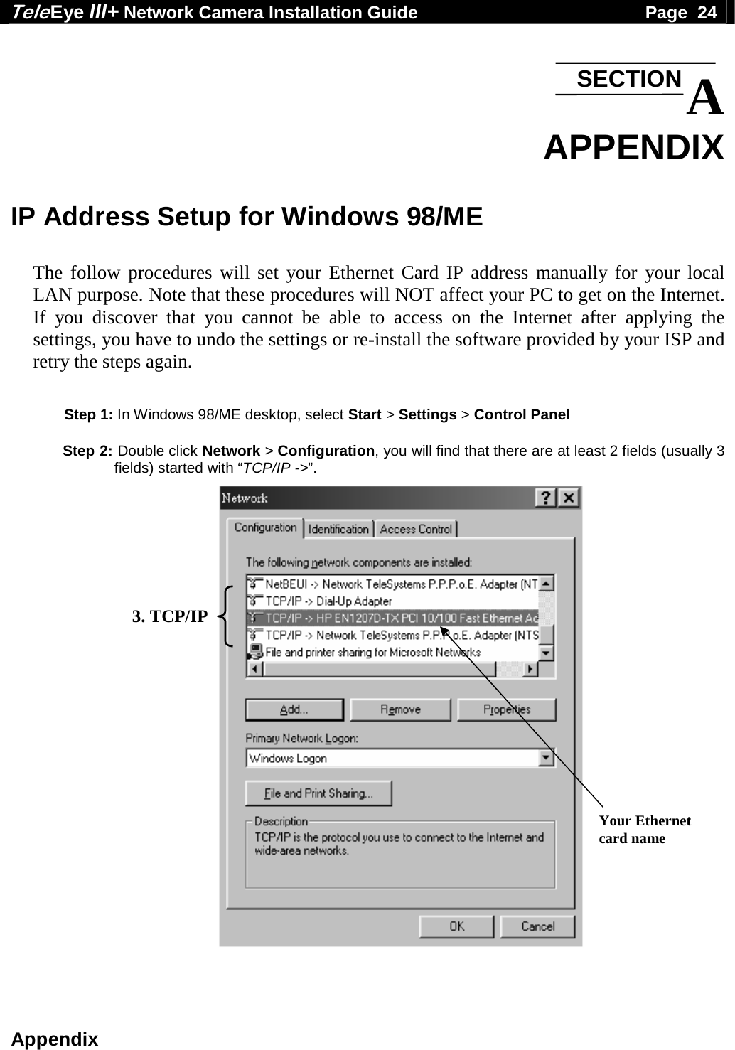
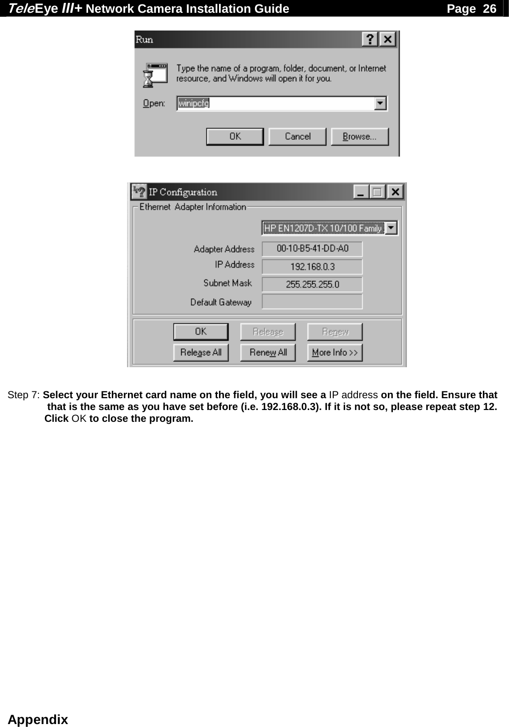
![Tele Eye III+ Network Camera Installation Guide Page 25 Appendix Two of them are very important for setup. One of them is used for your local intranet (the field may contain the name of your Ethernet card), the other one is used for your broadband Internet connection. An example is shown in the following figure. TCP/IP-> HP EN1207D-TX PCI 10/100 Fast Ethernet Adaptor Used for Intranet (local network) TCP/IP-> Network TeleSystems P.P.P.o.E Adaptor Broadband Internet Access (Point-to-Point Protocol over Ethernet) Note that the name of these two TCP/IP adaptors may be different on your computer. You have to identify the purpose of each corresponding adaptor. Step 3: Choose TCP/IP->[Your Ethernet card name] > Click Properties > IP address, enter an IP address “192.168.0.3” and subnet mask “255.255.255.0” Step 4: Click OK and OK and reboot the computer. Step 5: After booting, ensure that the computer can still be connected to the Internet. Step 6: You have to confirm the IP address has been correctly set on your computer. On your windows, click start > run, type “winipcfg” at Open field and pressed OK button, then you will see a IP Configuration program shown as figure.](https://usermanual.wiki/Signal-Communications/SCNF-040113/User-Guide-453578-Page-30.png)