Smart Modular Technologies 901782 Bluetooth RS232 DTE adapter User Manual 11 1 Exposure to Radio Frequency Radiation
Smart Modular Technologies Bluetooth RS232 DTE adapter 11 1 Exposure to Radio Frequency Radiation
UserManual.wiki
>
Smart Modular Technologies
>
901782 User Manual
Users Manual
Navigation menu
Upload a User Manual
Namespaces
Wiki Guide
HTML
PDF
Info
Views
User Manual
Discussion / Help
Navigation
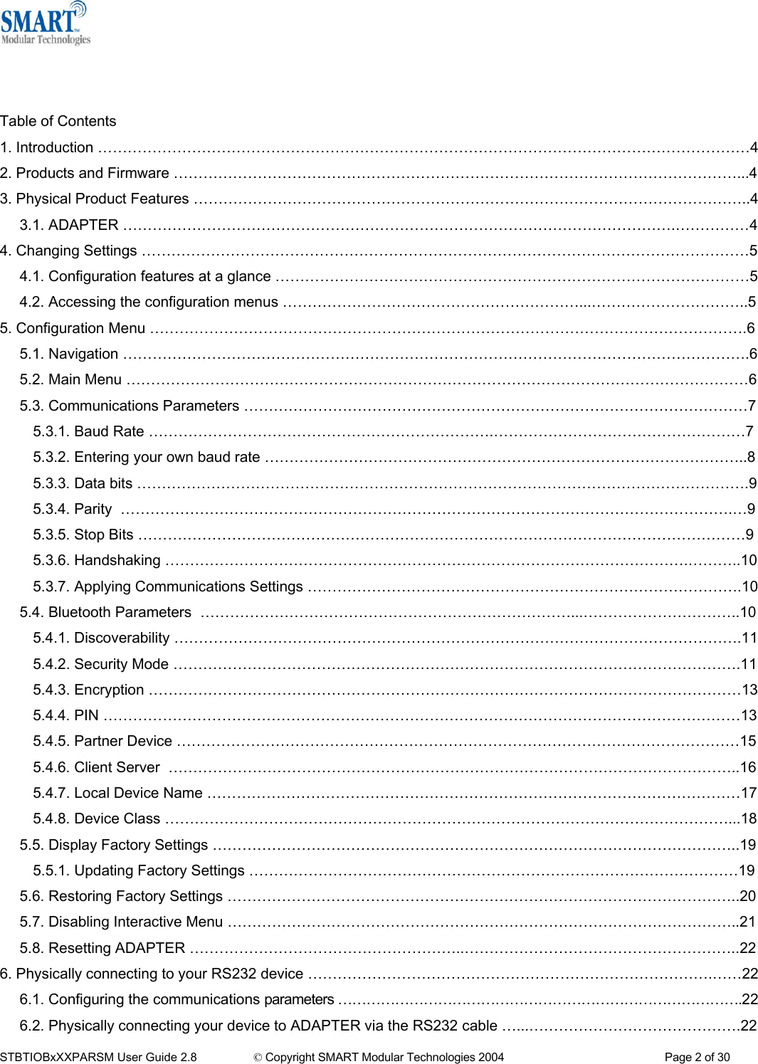
![5. Configuration Menu 5.1. Navigation As a general principle, from any menu screen hitting the “Enter” key refreshes the current menu and hitting 0 returns the user to the previous menu. Menu selection is performed by pressing the number on your keyboard that corresponds to the number listed on the menu item you wish to view/configure. Reminder: The configuration menu is not available while a radio (Bluetooth) connection is established. 5.2. Main Menu ======================================== ============== MAIN MENU =============== ============== Version 3.02 ================ ======================================== Key [1] - Modify COMM Settings Key [2] - Modify Bluetooth Settings Key [3] - Display Current Settings Key [4] - Restore Factory Settings Key [5] - Disable Interactive Menu Key [6] - Upgrade DFU STBTIOBxXXPARSM User Guide 2.8 © Copyright SMART Modular Technologies 2004 Page 6 of 30](https://usermanual.wiki/Smart-Modular-Technologies/901782/User-Guide-446564-Page-6.png)
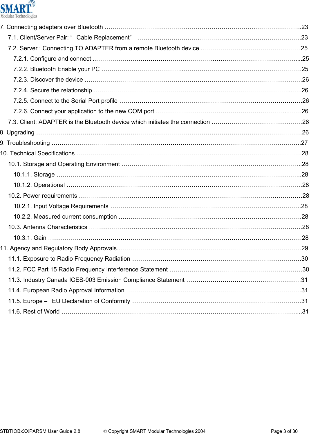
![5.3. Communications Parameters Selecting option 1 from the “Main Menu” menu displays the Communications settings menu. It is from this menu that all available serial port settings can be changed. The available options are detailed below. ================================================= Modify COMM Settings ============ ========================================Key [0] - MAIN MENU Key [1] - Set Baud Rate Key [2] - Set Parity Key [3] - Set Stop Bits Key [4] - Apply COMM Settings Key [4] - 115200 Key [5] - 57600 Key [6] - 38400 Key [7] - 19200 Key [8] - 9600 Key [9] - 4800 Key [a] - 2400 Key [b] - 1200 The factory set communications parameters for your ADAPTER are as follows… ====================================================== MAIN MENU ============================== Version 3.02 =======================================================Key [1] - Modify COMM Settings Key [2] - Modify Bluetooth Settings Key [3] - Display Current Settings Key [4] - Restore Factory Settings Key [5] - Disable Interactive Menu Key [6] - Upgrade DFU Key [c] - 300 Key [d] – Enter your own baud rate Baud rate: 115200 (actual 115168) - applied Baud Rate: 115,200 Data Bits: 8 (non-configurable) Parity: None Stop Bits: 1 Flow Control Hardware You can alter these settings by using the configuration menu options shown below. 5.3.1. Baud Rate Select option 1 to access the baud rate menu below) to change baud rate. ====================================================== Set Baud Rate =============== Key [0] – PREVIOUS MENU Key [1] - 921600 Key [2] - 460800 Key [3] - 230400 Any changes made in this menu will be remembered when leaving, and will be applied by selecting option 4 “Apply COMM Settings” From the previous ”Modify COMM Settings” menu. Selecting any other option will store the appropriate configuration selection. A range of popular pre-set baud rates is offered in this menu along with an option for you to set your own. Due to some technical limitations, it is not possible for the product to achieve all of these baud rates exactly, although most of them are available within 1%. Normal RS232 operation is not affected by such small differences in data rates unless long streams of continuous data are being used. The actual baud rate achieved will be displayed next to your selection. STBTIOBxXXPARSM User Guide 2.8 © Copyright SMART Modular Technologies 2004 Page 7 of 30](https://usermanual.wiki/Smart-Modular-Technologies/901782/User-Guide-446564-Page-7.png)
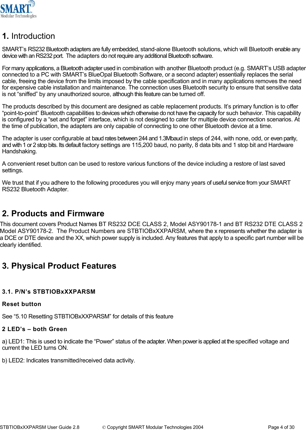
![5.3.2. Entering your own baud rate =================================================== Set Baud Rate ==============Key [0] – PREVIOUS MENU Key [1] - 921600 Key [2] - 460800 Key [3] - 230400 Key [4] - 115200 Key [5] - 57600 Key [6] - 38400 Key [7] - 19200 Key [8] - 9600 Key [9] - 4800 Key [a] - 2400 Key [b] - 1200 Key [c] - 300 Key [d] – Enter your own baud rate Baud rate: 115200 (actual 115168) - applied Selecting option (d) from the “Set Baud Rate” Menu allows the user to configure the product to operate at any baud rate the user desires between 244 baud and 1.3M baud. The adapter will calculate the nearest actual baud rate it is able to achieve and display it next to your selection, as shown in the configuration menu’s below. Enter the new baud rate: Enter the baud rate value you want, followed by hitting the return (ENTER) key. The value you enter must be between 244 and 1382400 otherwise an error will be shown. You will be given a further opportunity to enter a valid value. Enter the new baud rate: 12345676 Error: The baud rate must be 7 digits or less Enter the new baud rate: Entering a valid number here such as shown left results in your selection being accepted and your baud rate selection being displayed at the bottom of the menu. Selecting 0 immediately returns you to the previous menu storing any changes you have made; selecting any other option will store the appropriate configuration selection. As shown below, your configuration selection will not actually be applied at this point. Enter the new baud rate: 15000 The Menu identifies this new selection as being unapplied. To apply this selection, select the “Apply COMM Settings” from the previous menu. This can be reached by selecting option “0”. Unapplied settings are discarded during a re-boot of the adapter. STBTIOBxXXPARSM User Guide 2.8 © Copyright SMART Modular Technologies 2004 Page 8 of 30](https://usermanual.wiki/Smart-Modular-Technologies/901782/User-Guide-446564-Page-8.png)
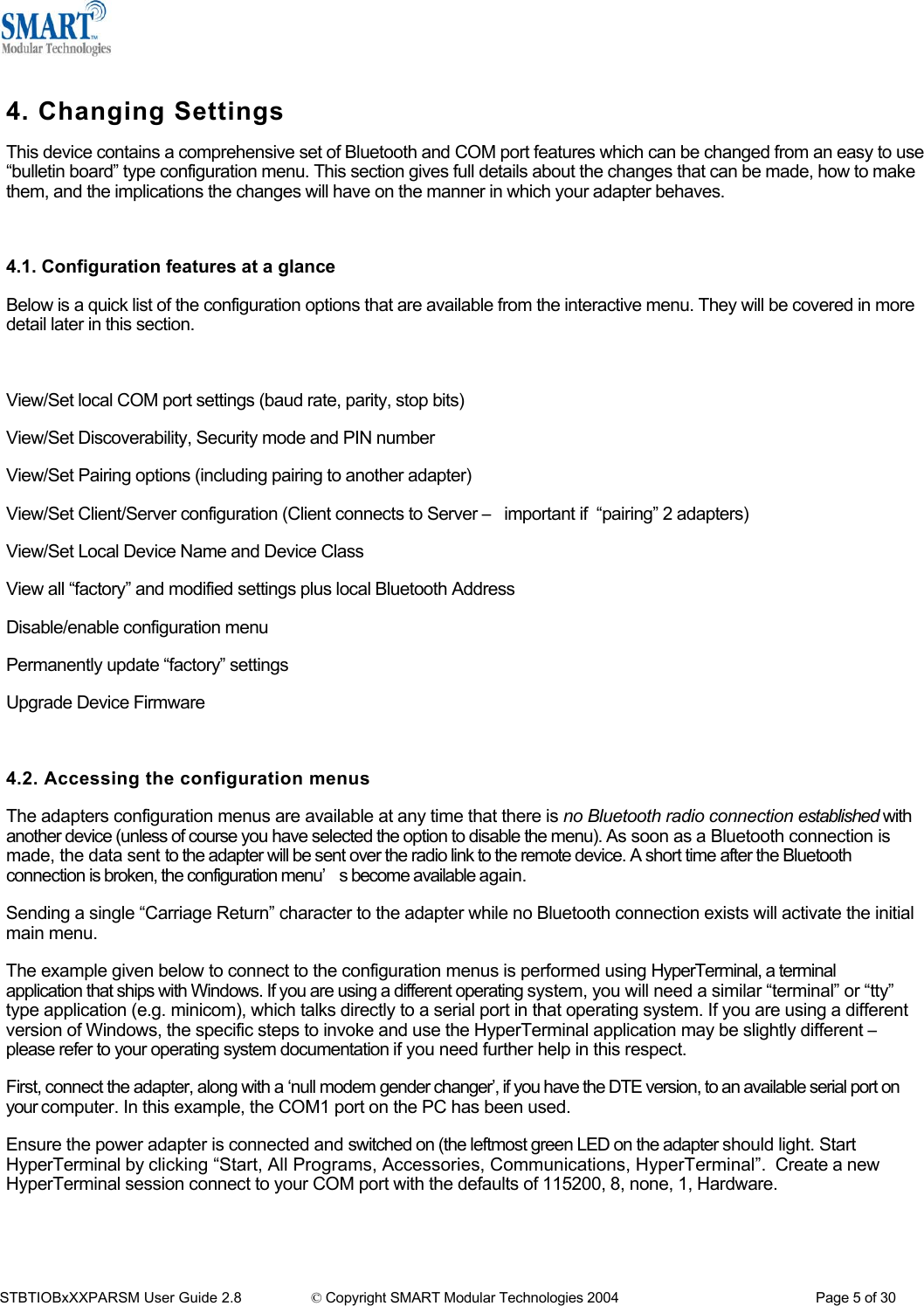
![5.3.3. Data bits Unfortunately this setting cannot be changed. The adapter only supports the 8 data bit format. Thus there is not a configuration menu option for this setting. 5.3.4. Parity =================================================== Modify COMM Settings ========== ========================================Key [0] - MAIN MENU Key [1] - Set Baud Rate Key [2] - Set Parity Key [3] - Set Stop Bits Key [4] - Apply COMM Settings Selecting option 2 from the “Modify COMM Settings” menu enters the Set Parity menu. ======================================================== Set Parity ========================================================Key [0] - PREVIOUS MENU Key [1] - NO parity Key [2] - ODD parity Key [3] - EVEN parity Parity: NO parity - unapplied The Set Parity menu is displayed. Selecting 0 immediately returns you to the previous menu storing any changes you have made; selecting any other option will store the appropriate configuration selection. As shown below, your configuration selection will not actually be applied at this point. Configuration changes are only applied when option 4 (Apply COMM settings) is selected from the previous “Modify COMM Settings” Menu. 5.3.5. Stop bits Option 3 from the “Modify COMM Settings” menu allows the user to change the Stop Bit setting. ================================================== Modify COMM Settings =========== ========================================Key [0] - MAIN MENU Key [1] - Set Baud Rate Key [2] - Set Parity Key [3] - Set Stop Bits Key [4] - Apply COMM Settings ====================================================== Set Stop Bits ======================================================== Key [0] - PREVIOUS MENU Key [1] - 1 stop bit Key [2] - 2 stop bits Stop Bits: 1 stop bit - applied Selecting 0 immediately returns you to the previous menu storing any changes you have made; selecting any other option will store the appropriate configuration selection. As shown below, your configuration selection will not actually be applied at this point. Configuration changes are only applied when option 4 (Apply COMM settings) is selected from the previous “Modify COMM Settings” Menu. Unapplied settings are discarded during a reboot of the ADAPTER. STBTIOBxXXPARSM User Guide 2.8 © Copyright SMART Modular Technologies 2004 Page 9 of 30](https://usermanual.wiki/Smart-Modular-Technologies/901782/User-Guide-446564-Page-9.png)
![5.3.6. Handshaking Handshaking is discussed in more detail in the section entitled “Handshaking Options” as it is not an option directly available from the menu. 5.3.7. Applying Communications Settings ================================================= Modify COMM Settings ========= ========================================Key [0] - MAIN MENU Key [1] - Set Baud Rate Key [2] - Set Parity Key [3] - Set Stop Bits Key [4] - Apply COMM Settings Changes to COM port settings are activated only by actively choosing to apply those settings. This is to minimize the disruption to the device configuration by having to reconfigure the terminal application after changing each setting. After selecting option 4 from the “Modify COMM Settings” menu, the following menu is displayed. Obviously the values displayed are dependant on your own individual configuration. =================================================== Apply COMM Settings ===================================================Baud rate: 115000 - UNAPPLIED (Currently 115200) Parity: ODD parity - UNAPPLIED (Currently NO parity) Stop Bits: 2 stop bits - UNAPPLIED (Currently 1 stop bit) Key [0] - PREVIOUS MENU Key [1] – Apply these settings Selecting 0 immediately returns you to the previous menu storing any changes you have made. Selecting “1” will immediately apply any new communications parameters you have selected from the other COMM menu’s. If you have changed any communications parameters, and wish to continue to access the configuration menu, you will need to update your terminal applications settings. The easiest method of performing this in HyperTerminal is to close and re-start the application, setting the new parameters during the initial application configuration. Apply the new COMM settings... Please reconfigure the terminal application if necessary_ 5.4. Bluetooth Parameters ====================================================== MAIN MENU ============================= Version 3.02 ========================================================Key [1] - Modify COMM Settings Key [2] - Modify Bluetooth Settings Key [3] - Display Current Settings Key [4] - Restore Factory Settings Key [5] - Disable Interactive Menu Key [6] - Upgrade DFU Selecting option 2 from the “Main Menu” menu displays the following Bluetooth settings menu. STBTIOBxXXPARSM User Guide 2.8 © Copyright SMART Modular Technologies 2004 Page 10 of 30](https://usermanual.wiki/Smart-Modular-Technologies/901782/User-Guide-446564-Page-10.png)
![================================================= Modify Bluetooth Settings ===================================================Key [0] - MAIN MENU Key [1] - Set Discoverability Key [2] - Set Security Mode Key [3] - Set Encryption Key [4] - Set PIN Key [5] - Set Partner Device Key [6] - Set Client/Server Key [7] - Set Local Name Key [8] - Set Class of Device After selecting option “1” from the “Modify Bluetooth Settings” menu, the following menu is displayed. It is from this menu that all available Bluetooth settings can be changed. The available options are detailed below. Selecting 0 immediately returns you to the previous menu storing any changes you have made 5.4.1. Discoverability Selecting option “1” will immediately render adapter “Discoverable”. This means that any other Bluetooth device can see adapter when it performs a device discovery. ====================================== =========== Set Discoverability ============= ====================================== Key [0] - PREVIOUS MENU Key [1] - On Key [2] - Off Discoverability: On Selecting option “2” immediately renders the adapter “non-discoverable”. No other Bluetooth devices will be able to see the adapter when they perform a device discovery. However, in this mode, your adapter is still “connectable”. This means that any other Bluetooth device that knows about your specific adapter (i.e. it knows the Bluetooth address of the individual unit) can still connect to it. You may wish to set this option to avoid confusion when many adapters exist in close proximity to each other. Unlike the communications settings, this Bluetooth setting is applied with immediate effect. 5.4.2. Security Mode After selecting option “2” from the “Modify Bluetooth Settings” menu, the following menu is displayed. =============================================== Set Security Mode =================================================== Key [0] - PREVIOUS MENU Key [1] - 1 (Low) Key [2] - 2 (Medium) Key [3] - 3 (High) Security Mode: 3 (High) The factory set security mode is 3 (Highest) Selecting 0 immediately returns you to the previous menu storing any changes you have made. Selecting option “1” will immediately place your ADAPTER into security mode 1. This is the lowest security mode that the ADAPTER can be configured to. Connections, including service discovery, can take place without the need for “pairing” or “bonding”. In mode 1, the Security Manager automatically accepts all access requests without initiating authentication, encryption, or authorization procedures. Any attempt by a remote application to perform authentication or encryption procedures will be rejected. STBTIOBxXXPARSM User Guide 2.8 © Copyright SMART Modular Technologies 2004 Page 11 of 30](https://usermanual.wiki/Smart-Modular-Technologies/901782/User-Guide-446564-Page-11.png)
![5.4.3. Encryption After selecting option 3 from the “Modify Bluetooth Settings” menu, the following menu is displayed. ================================================= Modify Bluetooth Settings ===================================================Key [0] - MAIN MENU Key [1] - Set Discoverability Key [2] - Set Security Mode Key [3] - Set Encryption Key [4] - Set PIN Key [5] - Set Partner Device Key [6] - Set Client/Server Key [7] - Set Local Name Key [8] - Set Class of Device The factory set Encryption mode is “Disabled”. This can be changed to enable “Point to Point” or “Point to Point & Broadcast”. ====================================================== Set Encryption ============== ========================================Key [0] - PREVIOUS MENU Key [1] - Disabled Key [2] - Point to Point Key [3] - Point to Point & Broadcast Encryption: Disabled Unlike the communications settings, this Bluetooth setting is applied with immediate effect. 5.4.4. PIN ============================================== Modify Bluetooth Settings ======= ========================================Key [0] - MAIN MENU Key [1] - Set Discoverability Key [2] - Set Security Mode Key [3] - Set Encryption Key [4] - Set PIN Key [5] - Set Partner Device Key [6] - Set Client/Server Key [7] - Set Local Name Key [8] - Set Class of Device The PIN (Personal Identification Number) is used to create a secure and trusted connection between 2 Bluetooth devices during a process called pairing or bonding. After selecting option 4 from the “Modify Bluetooth Settings” menu, the following menu is displayed. ======================================================= Set PIN ================ ========================================Key [0] - PREVIOUS MENU Key [1] - “ADAPTER” Key [2] - “1234” Key [3] - “01234567” Key [4] - Enter your own pin PIN Code: RS232 The PIN can be any combination of printable characters. The PIN is only used when the adapter is configured to be in security mode 2 or 3 (High or Medium security) The factory set PIN is “1234”. This can be changed to a range of pre-selected values, or you may enter you own combination up to a maximum of 8 characters. Selecting 0 immediately returns you to the previous menu storing any changes you made. STBTIOBxXXPARSM User Guide 2.8 © Copyright SMART Modular Technologies 2004 Page 13 of 30](https://usermanual.wiki/Smart-Modular-Technologies/901782/User-Guide-446564-Page-13.png)
![Selecting option 4 from the “Set PIN” menu will display the following menu below. ======================================================== Set PIN ================= ========================================Key [0] - PREVIOUS MENU Key [1] - “ADAPTER” Key [2] - “1234” Key [3] - “01234567” Key [4] - Enter your own pin PIN Code: In this field, you can enter your desired PIN code. This can be any printable alphanumeric character or symbol, but you should take care to choose a PIN appropriately remembering that some Bluetooth devices (e.g. cell phones) only have limited input mechanisms and may not have a full range of characters available. Enter the new pin: Enter the new pin: 5555555555 Error: The pin must be 8 characters or less Enter the new pin: Due to memory considerations the length of the PIN code is restricted to 8 characters. If you try to create a PIN code that is larger than this, an error message is generated and you will be given another opportunity to enter your own PIN Once you have entered the PIN you want, you should complete your request by hitting the “ENTER” key, whereupon the original menu is displayed, showing your new PIN selection. Enter the new pin: RS232 ======================================================= Set PIN ================ ========================================Key [0] - PREVIOUS MENU Key [1] - "ADAPTER" Key [2] - "1234" Key [3] - "01234567" Key [4] - Enter your own pin PIN Code: 1234 If your ADAPTER is to be configured into Client mode, this is the PIN that will be used by ADAPTER to initiate pairing with the remote device before any connection is made. If your remote device is another ADAPTER in Server mode, you will need to ensure that “both” devices are configured to use the same PIN number. Unlike the communications settings, this Bluetooth setting is applied with immediate effect. STBTIOBxXXPARSM User Guide 2.8 © Copyright SMART Modular Technologies 2004 Page 14 of 30](https://usermanual.wiki/Smart-Modular-Technologies/901782/User-Guide-446564-Page-14.png)
![5.4.5. Partner Device This feature serves 2 purposes. In Server mode it shows the address of the last device to successfully bond and connect. In Client mode, it shows the device to which the product will attempt to pair/connect. A remote device address must first be entered into the “partner device” section before the product, configured in Client mode, will be able to initiate any connections to that remote device. Adding a partner device using this feature does not stop remote devices bonding with ADAPTER while it is in Server Mode. ================================================= Modify Bluetooth Settings ===================================================Key [0] - MAIN MENU Key [1] - Set Discoverability Key [2] - Set Security Mode Key [3] - Set Encryption Key [4] - Set PIN Key [5] - Set Partner Device Key [6] - Set Client/Server Key [7] - Set Local Name Key [8] - Set Class of Device Once a remote device has successfully partnered with ADAPTER, no other Bluetooth device will be able to connect until the pairing has been cleared. The pairing can be expired either by interacting with this menu option, or by invoking a “short” reset by pressing the reset button. After selecting option 5 from the “Modify Bluetooth Settings” menu, the following menu is displayed. ==================================================== Set Partner Device ======================================================Key [0] - PREVIOUS MENU Key [1] - Add partner device Partner Device: 000a-4f-00082d (not paired) Selecting 0 immediately returns you to the previous menu storing any changes you have made. If a remote Bluetooth device has previously paired to the ADAPTER then this menu will display the first time the “Set Partner Device” menu is access. Selecting option “1” brings up the following menu. You should enter here the Bluetooth Address (BD_ADDR) of the remote device you wish to pair to followed by ENTER. This should be in the same format as indicated on the products label (NAP-UAP-LAP, for those of you who know) =================================================== Set Partner Device =======================================================Key [0] – PREVIOUS MENU Key [1] - Add partner device Enter the address of the partner device: 000a-4f-00082d (not paired) This will now refresh the menu with the address just entered and changes the option to allow removal of the entered device. The option to remove this newly entered device exists at this point should you have made a mistake. Enter the address of the partner device: Once ADAPTER has successfully paired with the remote device (or vice-versa) the menu will update to give the user the option to expire the pairing. This can also be achieved by performing a “short” reset using the reset button. Enter the address of the partner device: 000a-4f-00082d STBTIOBxXXPARSM User Guide 2.8 © Copyright SMART Modular Technologies 2004 Page 15 of 30](https://usermanual.wiki/Smart-Modular-Technologies/901782/User-Guide-446564-Page-15.png)
![This expiration only deletes the Link Key created during pairing and doesn’t remove the device itself. ==================================================== Set Partner Device ======================================================Key [0] - PREVIOUS MENU Key [1] - Remove partner device Key [2] – Expire pairing Partner device: 000a-4f-00082d (paired) Selecting the option to remove the partner device as below will remove both the link key created during the pair, and it will remove the partner device itself from the memory of ADAPTER. All the settings in this section are applied with immediate effect. Pairing expired… ================================================== Set Partner Device ========== ========================================Key [0] - PREVIOUS MENU Key [1] - Remove partner device Key [2] – Expire pairing Partner device: 000a-4f-00082d ( not paired) 5.4.6. Client/Server ============================================== Modify Bluetooth Settings ======= ========================================Key [0] - MAIN MENU Key [1] - Set Discoverability Key [2] - Set Security Mode Key [3] - Set Encryption Key [4] - Set PIN Key [5] - Set Partner Device Key [6] - Set Client/Server Key [7] - Set Local Name Key [8] - Set Class of Device After selecting option 6 from the “Modify Bluetooth Settings” menu, the following menu is displayed. Selecting 0 immediately returns you to the previous menu storing any changes; selecting any other option will store the appropriate configuration selection. The default configuration of your ADAPTER is set to “Server” operation. This means that the ADAPTER will wait for devices to connect to it. Changing this setting to “Client” will put the ADAPTER into a state where it will attempt to connect to the device contained in its internal database. This remote device is entered into ADAPTER using the previous menu option, or by pairing with the ADAPTER from the remote device while ADAPTER is in server mode. ==================================================== Set Client/Server =======================================================DEVICE MUST BE REBOOTED IN ORDER TO APPLY THIS SETTING Key [0] - PREVIOUS MENU Key [1] - Server (accepts incoming connections) Key [2] - Client (initiates connections) Client/Server: Server (accepts incoming connections) It is this option that requires interaction if you wish to configure 2 ADAPTER’s to communicate to each other to create a “true” cable replacement scenario. Unlike most other Bluetooth settings, the ADAPTER requires re-booting before this option will be enabled, although it is recommended that the modification of this setting is left until all other configuration changes have been made. STBTIOBxXXPARSM User Guide 2.8 © Copyright SMART Modular Technologies 2004 Page 16 of 30](https://usermanual.wiki/Smart-Modular-Technologies/901782/User-Guide-446564-Page-16.png)
![5.4.7. Local Device Name In scenario’s where more than 1 ADAPTER is to be used in the same geographical location (i.e. they are all in range of each other/the controlling device), it may be pertinent to change the name of each device to more easily identify each individual device. ============================================== Modify Bluetooth Settings ======= ========================================Key [0] - MAIN MENU Key [1] - Set Discoverability Key [2] - Set Security Mode Key [3] - Set Encryption Key [4] - Set PIN Key [5] - Set Partner Device Key [6] - Set Client/Server Key [7] - Set Local Name Key [8] - Set Class of Device After selecting option 7 from the “Modify Bluetooth Settings” menu, the following menu is displayed. ==================================================== Set Local Name ============ ========================================Key [0] - PREVIOUS MENU Key [1] - “SMBT-178 RS232 SPA1” Key [2] - “SMBT-178 RS232 SPA2” Key [3] - “SPA_1” Key [4] - “SPA_2” Key [5] - Enter your own local device name Local Device Name: SMBT-178 RS232 SPA1 ==================================================== Set Local Name ============ ========================================Key [0] - PREVIOUS MENU Key [1] - “SMBT-178 RS232 SPA1” Key [2] - “SMBT-178 RS232 SPA2” Key [3] - “SPA_1” Key [4] - “SPA_2” Key [5] - Enter your own local device name Local Device Name: SMBT RS232 Adapter The Factory setting for the local device name is “SMBT RS232 Adapter”. Selecting 0 immediately returns you to the previous menu storing any changes; selecting any other option will store the appropriate configuration selection. Selecting options 1-4 configure the ADAPTER to use one of the pre-configured name options. As an example we will choose ‘1’ After making the selection the devices local name immediately updates. Enter the new local name: If you wish to use a name other than those listed, you’ll need to select option 5. Enter your own local device name: aaaaaaaaaaaaaaaaaaaaaaaaaaaaaaaaaaaaaaaaaaaaaaaaaaaaa Error: The local name must be 31 characters or less Enter the new local name: Enter the name you’d like your ADAPTER to display. Memory constraints mean that you must ensure that your desired name is less than 31 characters. You cannot use the “delete” key as this will be interpreted as part of the name. STBTIOBxXXPARSM User Guide 2.8 © Copyright SMART Modular Technologies 2004 Page 17 of 30](https://usermanual.wiki/Smart-Modular-Technologies/901782/User-Guide-446564-Page-17.png)
![Press ENTER when you are satisfied with your name. Enter the new local name: RS232 Test Adapter ==================================================== Set Local Name ============ ========================================Key [0] - PREVIOUS MENU Key [1] - “SMBT-178 RS232 SPA1” Key [2] - “SMBT-178 RS232 SPA2” Key [3] - “SPA_1” Key [4] - “SPA_2” Key [5] - Enter your own local device name Local Device Name: RS232 Test Adapter The menu will now update with your chosen name selection. 5.4.8. Device Class The Factory setting for the Class of device is “Peripheral”. ============================================== Modify Bluetooth Settings ======= ========================================Key [0] - MAIN MENU Key [1] - Set Discoverability Key [2] - Set Security Mode Key [3] - Set Encryption Key [4] - Set PIN Key [5] - Set Partner Device Key [6] - Set Client/Server Key [7] - Set Local Name Key [8] - Set Class of Device Selecting 0 immediately returns you to the previous menu storing any changes; selecting any other option will store the appropriate configuration selection. This menu option allows the selection of a number of different device types as defined by the Bluetooth specification. IMPORTANT NOTE: Changing this Class of Device setting does not alter the published functionality of the product. It will continue to offer ONLY One Serial port profile connection. This option does not take effect until ADAPTER is re-booted (power switched off and then on again). =================================================== Set Class of Device ====================================================== DEVICE MUST BE REBOOTED IN ORDER TO APPLY THIS SETTING Key [0] - PREVIOUS MENU Key [1] - Peripheral Key [2] - Desktop Key [3] - Laptop Key [4] - Imaging Key [5] - Phone/Modem Key [6] - LAN Class of Device: Peripheral STBTIOBxXXPARSM User Guide 2.8 © Copyright SMART Modular Technologies 2004 Page 18 of 30](https://usermanual.wiki/Smart-Modular-Technologies/901782/User-Guide-446564-Page-18.png)
![5.5. Display Factory Settings Selecting option 3 from the “Main Menu” menu displays the following Current settings menu. ====================================================== MAIN MENU ============================== Version 3.02 =======================================================Key [1] - Modify COMM Settings Key [2] - Modify Bluetooth Settings Key [3] - Display Current Settings Key [4] - Restore Factory Settings Key [5] - Disable Interactive Menu Key [6] - Upgrade DFU =============================================== Display Current Settings ======= ========================================Baud rate: 115200 (Actual: 115168) Parity: NO parity Stop Bits: 1 stop bit Local Device: 0002-5B-00A5A5 Local Device Name: SMBT RS232 Adapter Discoverability: On Security Mode: 3 (High) Encryption: Disabled PIN Code: 1234 Partner Device: None Client/Server: Server (accepts incoming connections) Class of Device: Peripheral Key [0] - MAIN MENU Key [1] - Save current settings as factory default settings The picture left shows the original factory settings for the product. The one item that will be different for each individual product will be the local device setting. This setting is unique for each individual Bluetooth device in existence and cannot be changed. 5.5.1. Updating Factory Settings =============================================== Display Current Settings ======= ========================================Baud rate: 115200 (Actual: 115168) Parity: NO parity Stop Bits: 1 stop bit Local Device: 0002-5B-00A5A5 Local Device Name: SMBT RS232 Adapter Discoverability: On Security Mode: 3 (High) Encryption: Disabled PIN Code: 1234 Partner Device: None Client/Server: Server (accepts incoming connections) Class of Device: Peripheral Key [0] - MAIN MENU Key [1] - Save current settings as factory default settings Selecting option 1 from this Current settings menu allows any user settings to be used to update the “factory” settings, providing some level of protection from losing application configuration settings during a device reset when the reset button is activated. STBTIOBxXXPARSM User Guide 2.8 © Copyright SMART Modular Technologies 2004 Page 19 of 30](https://usermanual.wiki/Smart-Modular-Technologies/901782/User-Guide-446564-Page-19.png)
![!!!!!!!!!!!!!!!!!!!!!!!!!!!!!!!!!!!!!!!!!!!!!!!!!!!!!!!!!!!!!!!!!! ! This option changes the factory settings ! ! The settings cannot be restored by the reset button ! ! Type PROCEED to apply changes ! ! Type any other character sequence to abort ! !!!!!!!!!!!!!!!!!!!!!!!!!!!!!!!!!!!!!!!!!!!!!!!!!!!!!!!!!!!!!!!!!! This is not something you really want to do unless you’re sure you have the settings as you want them and are sure you can remember them, as there is no way back from here… Entering any character other than that required will abort the update. The PROCEED command is case sensitive and must be followed by <ENTER>. Aborting… !!!!!!!!!!!!!!!!!!!!!!!!!!!!!!!!!!!!!!!!!!!!!!!!!!!!!!!!!!!!!!!!!! ! This option changes the factory settings ! ! The settings cannot be restored by the reset button ! ! Type PROCEED to apply changes ! ! Type any other character sequence to abort ! !!!!!!!!!!!!!!!!!!!!!!!!!!!!!!!!!!!!!!!!!!!!!!!!!!!!!!!!!!!!!!!!!! PROCEED_ All the settings in this section are applied with immediate effect. Storing new factory settings…Complete 5.6. Restoring Factory Settings Selecting option 4 from the main menu displays the following restore factory settings menu. ====================================================== MAIN MENU ============================ Version 3.02 ============= ========================================Key [1] - Modify COMM Settings Key [2] - Modify Bluetooth Settings Key [3] - Display Current Settings Key [4] - Restore Factory Settings Key [5] - Disable Interactive Menu Key [6] - Upgrade DFU STBTIOBxXXPARSM User Guide 2.8 © Copyright SMART Modular Technologies 2004 Page 20 of 30](https://usermanual.wiki/Smart-Modular-Technologies/901782/User-Guide-446564-Page-20.png)
![Be sure to take a note of, or print these settings, as you will need to ensure that the next time you attempt to communicate with your ADAPTER you use these new settings. Remember that the original factory settings may have been updated using the previous menu. All the settings in this section are applied with immediate effect. ================================================= Restore Factory Settings ============ ========================================Baud rate: 115200 (Actual: 115168) Parity: NO parity Stop Bits: 1 stop bit Local Device Name: ADAPTER BB RS232 Converter Discoverability: On Security Mode: 3 (High) Encryption: Disabled PIN Code: 1234 Partner Device: None Client/Server: Server (accepts incoming connections) Class of Device: Peripheral Key [0] - MAIN MENU Key [1] - Restore these factory settings 5.7. Disabling Interactive Menu ====================================================== MAIN MENU ============================ Version 3.02 ============= ========================================Key [1] - Modify COMM Settings Key [2] - Modify Bluetooth Settings Key [3] - Display Current Settings Key [4] - Restore Factory Settings Key [5] - Disable Interactive Menu Key [6] - Upgrade DFU Some RS232 devices (GPS devices for example) emit a continuous stream of data regardless of whether a cable is connected. When no Bluetooth connection exists, this data can actually appear as commands to the menu and change settings that render the adapter inoperable. Disabling the menu, stops the adapter being unwontedly re-configured in this manner. Selecting option 5 from the main menu displays the following Disable Interactive menu. Selecting option 1 from this menu means that no further interaction with the menu will be possible until the device has been completely reset to it’s factory defaults by performing a “long” reset from the reset button. =============================================== Disable Interactive Menu ======= Key [0] – MAIN MENU Key [1] Disable menu (re-enable by restoring default with a long reset) Disabling now… STBTIOBxXXPARSM User Guide 2.8 © Copyright SMART Modular Technologies 2004 Page 21 of 30](https://usermanual.wiki/Smart-Modular-Technologies/901782/User-Guide-446564-Page-21.png)
![====================================================== MAIN MENU ============================= Version 3.02 ========================================================Key [1] - Modify COMM Settings Key [2] - Modify Bluetooth Settings Key [3] - Display Current Settings Key [4] - Restore Factory Settings Key [5] - Disable Interactive Menu Key [6] - Upgrade DFU From the main menu select option 2 “Modify Bluetooth Settings”. The following menu is displayed Select option 5 “Set Partner Device”. This tells the Client ADAPTER what remote device it is supposed to try to connect to. ================================================= Modify Bluetooth Settings ===================================================Key [0] - MAIN MENU Key [1] - Set Discoverability Key [2] - Set Security Mode Key [3] - Set Encryption Key [4] - Set PIN Key [5] - Set Partner Device Key [6] - Set Client/Server Key [7] - Set Local Name Key [8] - Set Class of Device ==================================================== Set Partner Device ======================================================Key [0] - PREVIOUS MENU Key [1] – Add partner device Enter the address of the partner device: You’ll need to add the Server ADAPTER into this menu option. Select option 1 to display the following menu. You should enter the Bluetooth Address (BD_ADDR) of the remote device you wish to pair (in our case this is 000A-4F-00082D) followed by ENTER. This should be in the same format as indicated on the products label (NAP-UAP-LAP, for those of you who know) Enter the address of the partner device: 000a-4f-00082d This will now refresh the menu with the address just entered. ==================================================== Set Partner Device ======================================================Key [0] - PREVIOUS MENU Key [1] - Remove partner device Partner device: 000a-4f-00082d (not paired) Select 0 to return to the previous menu and select option 6 “Set Client/Server” STBTIOBxXXPARSM User Guide 2.8 © Copyright SMART Modular Technologies 2004 Page 24 of 30](https://usermanual.wiki/Smart-Modular-Technologies/901782/User-Guide-446564-Page-24.png)
![============================================== Modify Bluetooth Settings ======= ========================================Key [0] - MAIN MENU Key [1] - Set Discoverability Key [2] - Set Security Mode Key [3] - Set Encryption Key [4] - Set PIN Key [5] - Set Partner Device Key [6] - Set Client/Server Key [7] - Set Local Name Key [8] - Set Class of Device After selecting option 6 from the “Modify Bluetooth Settings” menu, the following menu is displayed. Select the client option. This setting is stored immediately and is not discarded upon a reboot. In fact it requires a reboot in order to activate it. Re-boot. When the Client ADAPTER is switched on, it will connect to the Server device you have entered in the menu above, assuming of course that the server device is also powered up. That’s it – it really is that simple. Connecting to your ADAPTER will vary depending on your application, but will usually consist of 3 Steps. ================================== ========== Set Client/Server =========== ================================== DEVICE MUST BE REBOOTED IN ORDER TO APPLY THIS SETTING Key [0] - PREVIOUS MENU Key [1] - Server (accepts incoming connections) Key [2] - Client (initiates connections) Client/Server: Server (accepts incoming connections) 7.2. Server : Connecting TO ADAPTER from a remote Bluetooth device 1 – Configuring the ADAPTER’s communications parameters. 2 – Physically connecting ADAPTER to your device. 3 – Connecting to ADAPTER from a remote device via Bluetooth and transferring data. There are many different scenarios whereby a connection can be made to an ADAPTER and consequently its attached device. The application scenarios will also depend on what sort of device you have attached to the ADAPTER. One working example is shown here for illustrative purposes, but the principle will be the same regardless of the device you are connecting to except perhaps the cabling arrangements your device might require. In this example we have connected a Tektronix TDS220 Oscilloscope to an ADAPTER and plugged in the power adapter included. No additional cables or gender changers were used in this application scenario. In order to communicate to the scope/RS232 ADAPTER we have connected a SMART USB adapter to a laptop with SMART’s BlueOpal Bluetooth software suite installed. If you are connecting to ADAPTER with a different manufacturers Bluetooth product, please refer to the manufacturers instructions for that product. If you are Bluetooth enabling your laptop with another SMART RS232 ADAPTER you should follow the previous sections instructions. 7.2.1. Configure and connect Configure the communications and Bluetooth parameters of the adapter as described in the above sections and physically connect it to your RS232 device. 7.2.2. Bluetooth Enable your PC Any PC based Bluetooth device could be used, but for this example we have used SMART’s USB adapter and BlueOpal Bluetooth software for Windows. STBTIOBxXXPARSM User Guide 2.8 © Copyright SMART Modular Technologies 2004 Page 25 of 30](https://usermanual.wiki/Smart-Modular-Technologies/901782/User-Guide-446564-Page-25.png)