Sokkia Topcon SMBT1 Bluetooth module User Manual MTS E
Sokkia Topcon Co., Ltd. Bluetooth module MTS E
User Manual End Product
SURVEYING INSTRUMENTS
Class 3R Laser Product
Class 1 LED Product OPERATOR'S MANUAL
Series SRX
SRX1
SRX2
SRX3
SRX5
Total Station
H18.09.21

Li-ion S Li-ion
This is the mark of the Japan Surveying
Instruments Manufacturers Association.
Class 3R Laser Product
Class 1 LED Product
SURVEYING INSTRUMENTS
Series SRX
SRX1
SRX2
SRX3
SRX5
Total Station
OPERATOR’S MANUAL
• Thank you for selecting the SRX1/2/3/5.
• Before using the instrument, please read this operator’s manual carefully.
• Verify that all equipment is included.
"26. STANDARD EQUIPMENT"
• SRX has a function to output data saved in Program mode (SDR) to a connected
host computer. Command operations from a host computer can also be
performed. For details, refer to “Interfacing with the SOKKIA SDR Electronic Field
Book” and “Command Explanations” manuals and ask your Sokkia agent.
• The specifications and general appearance of the instrument may be altered at
any time and may differ from those appearing in brochures and this manual.
• Some of the diagrams shown in this manual may be simplified for easier
understanding.
ii
HOW TO READ THIS MANUAL
Regarding other manuals
•Manuals 2, 3, and 4 below are electronic manuals provided on a CD-ROM in PDF format ( ).
•The SRX comes equipped with 4 manuals for operation information:
1. SRX Operator’s Manual (this manual):
Explains basic operation and functions of the SRX.
2. Series SRX SDR Software Reference Manual :
Explains advanced measurement operations using the SRX in Program mode (SDR), and
methods for managing measured data.
3. SFX Dial-Up Program Explanations :
Explains how to send and receive data using the SFX function
4. Series SRX Quick Manual :
Simplified explanations of operations such as Auto-Tracking to allow users to get started
straight away.
Symbols
The following conventions are used in this manual.
[Softkey] etc. : Indicates softkeys on the display and window dialog buttons.
{Key} etc. : Indicates keys on the operation panel.
<Setting out> etc.: Indicates screen titles.
Notes regarding manual style
• Except where stated, “SRX” means “SRX1/SRX2/SRX3/SRX5” in this manual.
• Screens and illustrations appearing in this manual are of SRX3.
• Location of softkeys in screens used in procedures is based on the factory setting. It is possible to
change the allocation of softkeys.
Softkey allocation: "21.6 Allocating Key Functions"
• Kodak Gray Card: KODAK is a registered trademark of Eastman Kodak Company.
:Indicates precautions and important items which should be read before
operations.
: Indicates the chapter title to refer to for additional information.
: Indicates supplementary explanation.
: Indicates an explanation for a particular term or operation.

iii
SURVEYING INSTRUMENTS
• Bluetooth: Bluetooth® is a registered trademark of Bluetooth SIG, Inc.
•Windows CE® is a registered trademark of Microsoft Corporation.
• All other company and product names featured in this manual are registered trademarks of each
respective organization.
Operation procedure
• Learn basic operations in "4. PRODUCT OUTLINE" and "5. BASIC OPERATION" before you read
each measurement procedure. An overview of the available SRX functions is given in
"4.1 Functions". For selecting options and inputting figures, see "5.1 Basic Key Operation".
• For Auto Tracking measurement, read this manual in conjunction with the On-demand Remote
Control System Manual.
• Measurement procedures are based on continuous measurement. Some information about
procedures when other measurement options are selected can be found in “Note” ().

iv
CONTENTS
1. PRECAUTIONS FOR SAFE OPERATION ................. 1
2. PRECAUTIONS........................................................... 4
3. LASER SAFETY INFORMATION ............................... 6
4. PRODUCT OUTLINE ................................................. 8
4.1 Functions ........................................................................... 8
4.2 Parts of the Instrument .................................................... 10
4.3 Mode Configuration ......................................................... 15
4.4 Bluetooth Wireless Technology ....................................... 16
5. BASIC OPERATION ................................................. 18
5.1 Basic Key Operation ....................................................... 18
5.2 Display Functions ............................................................ 23
5.3 Inputting Characters using SIP Code (Input Panel) ........ 29
5.4 SETTINGS Mode ............................................................ 30
6. USING THE CF CARD SLOT ................................... 32
6.1 Inserting/Removing the CF Card ..................................... 32
7. USING THE BATTERY ............................................ 34
8. CONNECTING TO EXTERNAL DEVICES ............... 36
8.1 Wireless Communication using Bluetooth Technology ... 36
8.2 Communication between the SRX and Companion Device
......................................................................................... 40
8.3 Connection via RS-232C cable ....................................... 42
8.4 Connecting to USB devices ............................................ 42
9. SETTING UP THE INSTRUMENT ........................... 44
9.1 Centering ......................................................................... 44
9.2 Levelling .......................................................................... 45
10. POWER ON/OFF ..................................................... 48
10.1 Resolving Software Issues .............................................. 49
10.2 Configuring the Touch Panel ........................................... 49
10.3 Powering the SRX ON/OFF from an External Instrument 50
11. TARGET SIGHTING ................................................. 51
11.1 Auto Pointing Settings ..................................................... 52
11.2 Auto-Pointing Function for Target Sighting ..................... 54
11.3 Manually Sighting the Target .......................................... 55
12. MEASUREMENT WITH AUTO TRACKING ............. 56

v
CONTENTS
12.1 Auto Tracking Settings .................................................... 56
12.2 Measurement with Auto Tracking .................................... 57
13. ANGLE MEASUREMENT ........................................ 60
13.1 Measuring the Horizontal Angle between Two Points
(Horizontal Angle 0°) ....................................................... 60
13.2 Setting the Horizontal Angle to a Required Value (Horizontal
Angle Hold) ..................................................................... 62
13.3 Turning the Instrument from the Reference Angle to a
Specified Angle ............................................................... 64
13.4 Angle measurement and Outputting the Data ................. 65
14. DISTANCE MEASUREMENT .................................. 66
14.1 Returned Signal Checking .............................................. 66
14.2 Distance and Angle Measurement .................................. 68
14.3 Using the Guide Light ...................................................... 68
14.4 REM Measurement ......................................................... 70
14.5 Distance Measurement and Outputting the Data ............ 70
15. COORDINATE MEASUREMENT ............................. 73
15.1 Entering Instrument Station Data .................................... 73
15.2 Azimuth Angle Setting ..................................................... 74
15.3 3-D Coordinate Measurement ......................................... 77
16. RESECTION MEASUREMENT ................................ 79
16.1 Coordinate Resection Measurement ............................... 80
16.2 Height Resection Measurement ...................................... 84
17. SETTING-OUT MEASUREMENT ............................ 89
17.1 Using the Guide Light ...................................................... 89
17.2 Distance Setting-out Measurement ................................. 90
17.3 Coordinates Setting-out Measurement ........................... 96
17.4 REM Setting-out Measurement ....................................... 99
18. OFFSET MEASUREMENT .................................... 102
18.1 Single-distance Offset Measurement ............................ 102
18.2 Angle Offset Measurement ........................................... 104
18.3 Two-distance Offset Measurement ............................... 106
19. MISSING LINE MEASUREMENT .......................... 109
19.1 Measuring the Distance between 2 or more Points ...... 109
19.2 Changing the Starting Point .......................................... 111
20. SURFACE AREA CALCULATION ......................... 113

vi
CONTENTS
21. CHANGING THE SETTINGS ................................. 118
21.1 Observation Conditions ................................................. 118
21.2 Instrument Configuration ............................................... 120
21.3 EDM Settings ................................................................ 123
21.4 Allocating User-defined Tabs ........................................ 126
21.5 Customizing Screen Controls ........................................ 129
21.6 Allocating Key Functions ............................................... 131
21.7 Units .............................................................................. 134
21.8 Date and Time ............................................................... 135
21.9 Changing Password ...................................................... 135
21.10 Restoring Default Settings ............................................ 136
22. WARNING AND ERROR MESSAGES .................. 137
23. CHECKS AND ADJUSTMENTS ............................ 140
23.1 Plate Level .................................................................... 140
23.2 Circular Level ................................................................ 141
23.3 Tilt Sensor ..................................................................... 142
23.4 Collimation .................................................................... 145
23.5 Reticle ........................................................................... 147
23.6 CCD reticle .................................................................... 149
23.7 Optical Plummet ............................................................ 151
23.8 Additive Distance Constant ........................................... 152
24. Power Supply System ............................................ 154
25. Target System ........................................................ 155
26. STANDARD EQUIPMENT ..................................... 157
27. Optional Accessories .............................................. 159
28. SPECIFICATIONS .................................................. 161
29. REGULATIONS ...................................................... 168
30. EXPLANATION ...................................................... 173
30.1 Manually Indexing the Vertical Circle by Face Left, Face
Right Measurement ....................................................... 174
30.2 Atmospheric Correction for High Precision Distance
Measurement ................................................................ 175
31. INDEX .................................................................... 177
1
1. PRECAUTIONS FOR SAFE OPERATION
For the safe use of the product and prevention of injury to operators and other persons as well as
prevention of property damage, items which should be observed are indicated by an exclamation point
within a triangle used with WARNING and CAUTION statements in this operator’s manual.
The definitions of the indications are listed below. Be sure you understand them before reading the
manual’s main text.
Definition of Indication
General
WARNING Ignoring this indication and making an operation error could possibly
result in death or serious injury to the operator.
CAUTION Ignoring this indication and making an operation error could possibly
result in personal injury or property damage.
This symbol indicates items for which caution (hazard warnings inclusive) is urged.
Specific details are printed in or near the symbol.
This symbol indicates items which are prohibited. Specific details are printed in or near
the symbol.
This symbol indicates items which must always be performed. Specific details are printed
in or near the symbol.
Warning
Do not use the unit in areas exposed to high amounts of dust or ash, in areas where there
is inadequate ventilation, or near combustible materials. An explosion could occur.
Do not perform disassembly or rebuilding. Fire, electric shock, burns, or hazardous
radiation exposure could result.
Never look at the sun through the telescope. Loss of eyesight could result.
Do not look at reflected sunlight from a prism or other reflecting object through the
telescope. Loss of eyesight could result.
Direct viewing of the sun during sun observation will cause loss of eyesight. Use a solar
filter (option), such as that in "27. OPTIONAL ACCESSORIES", for sun observation.
When securing the instrument in the carrying case make sure that all catches, including
the side catches, are closed. Failure to do so could result in the instrument falling out
while being carried, causing injury.
Caution
Do not use the carrying case as a footstool. The case is slippery and unstable so a
person could slip and fall off it.

1. PRECAUTIONS FOR SAFE OPERATION
2
Power Supply
Do not place the instrument in a case with a damaged catch, belt or handle. The case or
instrument could be dropped and cause injury.
Do not wield or throw the plumb bob. A person could be injured if struck.
Do not touch the instrument or look through the telescope eyepiece while the motor drive
is in operation. Hands could be caught in moving parts or an eye could be struck by the
telescope and cause injury.
Secure handle to main unit with handle locks. Failure to properly secure the handle could
result in the unit falling off while being carried, causing injury.
Tighten the adjustment tribrach clamp securely. Failure to properly secure the clamp
could result in the tribrach falling off while being carried, causing injury.
Warning
Do not disassemble, rebuild, mutilate, incinerate, heat or short circuit the battery and
charger. Fire, electric shock, burns or an explosion could result.
Do not use voltage other than the specified power supply voltage. Fire or electrical shock
could result.
Do not use damaged power cords, plugs or loose outlets. Fire or electric shock could
result.
Do not use power cords other than those designated. Fire could result.
Do not place articles such as clothing on the battery charger while charging batteries.
Sparks could be induced, leading to fire.
Use only the specified battery charger to recharge batteries. Other chargers may be of
different voltage rating or polarity, causing sparking which could lead to fire or burns.
Do not heat or throw batteries into fire. An explosion could occur, resulting in injury.
To prevent shorting of the battery in storage, apply insulating tape or equivalent to the
terminals. Otherwise shorting could occur resulting in fire or burns.
Do not use batteries or the battery charger if wet. Resultant shorting could lead to fire or
burns.
Do not connect or disconnect power supply plugs with wet hands. Electric shock could
result.
Do not use the battery, charger or AC (power) cable for any other equipment or purpose.
Fire or burns caused by ignition could result.
Do not short circuit the battery. Fire or burns caused by heat or ignition could result.

3
1. PRECAUTIONS FOR SAFE OPERATION
Tripod
Bluetooth wireless technology
Caution
Do not touch liquid leaking from batteries. Harmful chemicals could cause burns or
blisters.
Caution
When mounting the instrument to the tripod, tighten the centering screw securely. Failure
to tighten the screw properly could result in the instrument falling off the tripod, causing
injury.
Tighten securely the leg fixing screws of the tripod on which the instrument is mounted.
Failure to tighten the screws could result in the tripod collapsing, causing injury.
Do not carry the tripod with the tripod shoes pointed at other persons. A person could be
injured if struck by the tripod shoes.
Keep hands and feet away from the tripod shoes when fixing the tripod in the ground. A
hand or foot stab wound could result.
Tighten the leg fixing screws securely before carrying the tripod. Failure to tighten the
screws could lead to the tripod legs extending, causing injury.
Warning
Do not use within the vicinity of hospitals. Malfunction of medical equipment could
result.
Use the instrument at a distance of at least 22 cm from anyone with a cardiac
pacemaker. Otherwise, the pacemaker may be adversely affected by the
electromagnetic waves produced and cease to operate as normal.
Do not use onboard aircraft. The aircraft instrumentation may malfunction as a result.
Do not use within the vicinity of automatic doors, fire alarms and other devices with
automatic controls as they may be adversely affected by the electromagnetic waves
produced resulting in malfunction and injury.
4
2. PRECAUTIONS
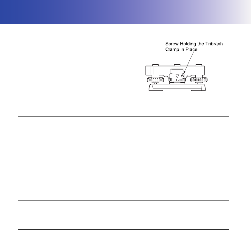
Tribrach Clamp
• When the instrument is shipped, the tribrach clamp is held
firmly in place with a locking screw to prevent the
instrument from shifting on the levelling base. Before using
the instrument the first time, loosen this screw with a
screwdriver. And before transporting it, tighten the locking
screw to fasten the tribrach clamp in place so that it will not
shift on the levelling base.
• The SRX handle can be removed. When operating the
SRX with the handle attached, always make sure that the
handle is securely fixed to the SRX body with the handle
lock levers.
Precautions concerning water and dust resistance
SRX conforms to IP64 specifications for waterproofing and dust resistance when the battery cover is
closed and connector caps are attached correctly.
• Be sure to correctly attach the connector caps to protect the SRX from moisture and dust particles.
• Make sure that moisture or dust particles do not come in contact with the terminal or connectors.
Contact with these parts may cause damage to the instrument.
• Make sure that the inside of the carrying case and the instrument are dry before closing the case.
If moisture is trapped inside the case, it may cause the instrument to rust.
Charging the battery
• The battery (BDC58) was not charged at the factory. Charge the battery fully before using the SRX.
The Lithium Battery
The lithium battery is used to maintain the SRX Calendar & Clock function. It can back up data for
approximately 5 years of normal use, but its lifetime may be shorter depending on circumstances.
Other precautions
• Never place the instrument directly on the ground. Sand or dust may cause damage to the screw
holes or the centering screw on the base plate.
• Do not aim the telescope at the sun. Use the solar filter to avoid causing internal damage to the
instrument when observing the sun.
"27. OPTIONAL ACCESSORIES"
• Do not perform automatic vertical rotation of the telescope when using the lens hood, diagonal
eyepiece, or solar filter. Such accessories may strike the SRX causing damage.
• Protect the instrument from heavy shocks or vibration.
• Protect the instrument from rain or drizzle with an umbrella or waterproof cover.
• When the operator leaves the instrument attached to the tripod, the vinyl cover should be placed on
the instrument.
• Never carry the instrument on the tripod to another site.
• Turn the power off before removing the battery.
• When placing the SRX in its case, first remove its battery and place it in the case in accordance with
the layout plan.

5
2. PRECAUTIONS
• Make sure that the instrument and the protective lining of the carrying case are dry before closing
the case. The case is hermetically sealed and if moisture is trapped inside, the instrument could
rust.
• Consult your Sokkia agent before using the instrument under special conditions such as long
periods of continuous use or high levels of humidity. In general, special conditions are treated as
being outside the scope of the product warranty.
Maintenance
• Wipe off moisture completely if the instrument gets wet during survey work.
• Always clean the instrument before returning it to the case. The lens requires special care. First,
dust it off with the lens brush to remove tiny particles. Then, after providing a little condensation by
breathing on the lens, wipe it with the wiping cloth.
• If the display is dirty, carefully wipe it with a soft, dry cloth. To clean other parts of the instrument or
the carrying case, lightly moisten a soft cloth in a mild detergent solution. Wring out excess water
until the cloth is slightly damp, then carefully wipe the surface of the unit. Do not use any organic
solvents or alkaline cleaning solutions.
• Store the instrument in a dry room where the temperature remains fairly constant.
• Check the tripod for loose fit and loose screws.
• If any trouble is found on the rotatable portion, screws or optical parts (e.g. lens), contact your Sokkia
agent.
• When the instrument is not used for a long time, check it at least once every 3 months.
"23. CHECKS AND ADJUSTMENTS"
• When removing the instrument from the carrying case, never pull it out by force. The empty carrying
case should be closed to protect it from moisture.
• Check the instrument for proper adjustment periodically to maintain the instrument accuracy.
6
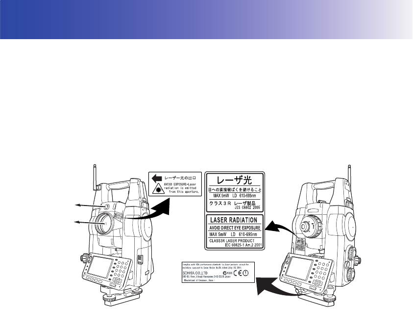
3. LASER SAFETY INFORMATION
SRX is classified as a Class 3R Laser Product and Class 1 LED Product according to IEC Standard
Publication 60825-1 Amd. 2: 2001 and United States Government Code of Federal Regulation FDA
CDRH 21CFR Part 1040.10 and 1040.11 (Complies with FDA performance standards for laser
products except for deviations pursuant to Laser Notice No.50, dated July 26, 2001.)
• EDM device in objective lens: Class 3R Laser Product
• (When using prism or reflective sheet as target Class 1 Laser Product
or when in Auto Tracking mode)
• Auto pointing device in objective lens: Class 1 Laser Product
• Guide light: Class 1 LED product
• EDM device is classified as Class 3R Laser Product when reflectorless measurement is selected.
When the prism or reflective sheet is selected as target, the output is equivalent to the safer class 1.
• The cumulative output during distance measurement and tracking in Auto Tracking mode is
equivalent to class 1.
Warning
• Use of controls or adjustments or performance of procedures other than those specified herein may
result in hazardous radiation exposure.
• Follow the safety instructions on the labels attached to the instrument as well as in this manual to
ensure safe use of this laser and LED product.
Caution
• Perform checks at start of work and periodic checks and adjustments with the laser beam emitted
under normal conditions.
• When the instrument is not being used, turn off the power and replace the lens cap.
• When disposing of the instrument, destroy the battery connector so that the laser beam cannot be
emitted.
• Operate the instrument with due caution to avoid injuries that may be caused by the laser beam
unintentionally striking a person in the eye. Avoid setting the instrument at heights at which the path
of the laser beam may strike pedestrians or drivers at head height.
LED beam
emitted from
here
Laser beam
emitted from
here

7
3. LASER SAFETY INFORMATION
• Never point the laser beam at mirrors, windows or surfaces that are highly reflective. The reflected
laser beam could cause serious injury.
• When using the laser-pointer function, be sure to turn OFF the output laser after distance
measurement is completed. Even if distance measurement is canceled, the laser-pointer function is
still operating and the laser beam continues to be emitted. (After turning ON the Laser-pointer, the
laser beam is emitted for 5 minutes, and then automatically switches OFF. )
• Only those who have been received training as per the following items shall use this product.
• Read the Operator’s manual for usage procedures for this product.
• Hazardous protection procedures (read this chapter).
• Requisite protective gear (read this chapter).
• Accident reporting procedures (stipulate procedures beforehand for transporting the injured and
contacting physicians in case there are laser induced injuries).
• Persons working within the range of the laser beam are advised to wear eye protection which
corresponds to the laser wavelength of the instrument being used
• Areas in which the lasers are used should be posted with laser warning notices.
• If Search or Track is selected in the Motor configuration "A.T. Setting", the laser beam will be emitted
from the objective lens when tracking a moving prism or searching for the center of the prism.
Tracking settings: "12.1 Auto Tracking Settings"
• The LED beam is emitted when the guide light is set to ON and the power is turned ON. Before
turning ON the power check that there are no persons in the LED beam path. Alternatively, always
set the guide light to OFF when you have finished measurement.
Guide light settings for tasks other than setting-out: "14.2 Using the Guide Light"
Guide light settings for setting-out: "14.2 Using the Guide Light"
8
4. PRODUCT OUTLINE
SRX has the following features to make operation more efficient.
1. Auto Tracking
The SRX will automatically follow a moving prism when the target is being moved to
the next measurement point, making surveying operations such as setting out faster
and smoother. Even when an obstacle causes the SRX to momentarily lose the
target, the On-demand Remote Control system allows the operator at the target to
move the SRX via remote control and re-acquire the target position.
"12. MEASUREMENT WITH AUTO TRACKING"
2. Bluetooth wireless technology
Bluetooth technology removes the need for cumbersome cables and provides
wireless communication functionality between the SRX and the On-demand
Remote Control system, data collectors and computers for even greater efficiency
gains in the field. Bluetooth device address and passkey settings afford greater
security when transmitting data wirelessly.
"8. CONNECTING TO EXTERNAL DEVICES"
3. High accuracy with reflectorless measurement
Sokkia’s own optics, electrical circuits, and processing algorithms combine to
provide superior reflectorless accuracy at distances as short as 30cm.
4. Various interface options
Data link options for the SRX include both a CF card slot and USB ports.
5. Full colour touch panel display
Not only does the colur screen improve usability, but the Graphic option allows the
user to visualise the current survey point during operation. In addition to the
operation keys, the touch panel with stylus pen offers another user-friendly method
for selecting screens and inputting characters.
"5.2 Display Functions"
4.1 Functions
9
4. PRODUCT OUTLINE
6. Guide light
Setting-out measurement etc. can be carried out effectively using the guide light.
The guide light is composed of a light that is divided into a red and a green light. A
poleman can ascertain whether to move to the right or left by checking the guide
light color.
"14.2 Using the Guide Light"
7. Sighting the target and performing distance measurement using Auto Pointing
Use the peep sight to bring the target roughly into the field of view. Then, press
[SRCH] to automatically sight the center of the target. The instrument and telescope
can be rotated manually by hand or, for more precise adjustments, by turning the
vertical and horizontal jogging knobs.
The instrument can be set to automatically measures the distance after Auto
Pointing has been completed. The search range can be set beforehand.
"11.2 Auto-Pointing Function for Target Sighting" and "21.3 EDM Settings"
8. Trigger Key for Easier Operation
Each screen contains a number of softkeys. Softkeys displayed in bold type control
the flow of measurement operation. Pressing the trigger key located on the side of
the SRX will perform exactly the same operation as the bolded softkey in the current
screen. This allows the user to continue operation without having to return to the
display to press softkeys, making operations such as resection measurement even
simpler.
"4.2 Parts of the Instrument Trigger key"
9. Wide range of advanced programs
One touch of the {PROGRAM} key allows the user to switch from Basic mode to
Program mode (SDR) in order to use advanced measurement programs. The
position of menus and softkeys can be user-defined for greater ease-of-use.
Switching modes: "4.3 Mode Configuration", rearranging softkeys:
"21.6 Allocating Key Functions"
10. SETTINGS Mode
One-touch of the {SETTINGS} key allows the user to jump to and from the
SETTINGS mode during operation without exiting measurement.
"4.3 Mode Configuration"
11.Sokkia’s original Independent Angle Calibration System (IACS) technology
Unaffected by errors in collimation and instrument setup, this internal calibration
technology provides an even higher level of stability and reliability for angle
measurement.
Independent angle calibration cannot be performed by the user. Consult your
Sokkia agent.
4. PRODUCT OUTLINE
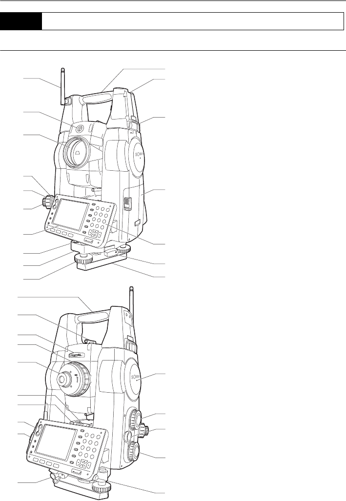
10
Parts and functions of the instrument
1 Handle
2 Tubular compass slot
3 Handle lock
4 Battery holder
5 Keyboard
6 Tribrach clamp
7 Base plate
8 Levelling foot screw
9 Circular level adjusting screws
10 Circular level
11 Display
12 Optical plummet eyepiece
13 Optical plummet reticle cover
14 Optical plummet focussing ring
15 Objective lens
(Includes " Laser-pointer
function")
16 Guide light
17 Bluetooth antenna
18 Instrument height mark
19 Vertical jogging knob
20 Trigger key
21 Horizontal jogging knob
22 Stylus pen holder
23 Combined communications and
power supply connector
24 CF card slot
"6. USING THE CF CARD SLOT"
25 USB ports
"8. CONNECTING TO EXTERNAL
DEVICES"
26 Plate level adjusting screw
27 Plate level
28 Telescope eyepiece screw
29 Telescope focussing ring
30 Laser radiation warning
indicator
31 Peep sight
32 Instrument center mark
4.2 Parts of the Instrument
17
16
15
14
13
12
11
10
9
8
6
5
4
3
2
1
7
32
18
19
20
21
31
30
29
28
27
26
25
24
23
22
11
4. PRODUCT OUTLINE
Vertical and Horizontal jogging knobs
The instrument and telescope can be rotated manually by hand or, for more precise adjustments,
by turning the vertical and horizontal jogging knobs.
The faster the jogging knobs are turned, the faster the instrument and telescope rotate.
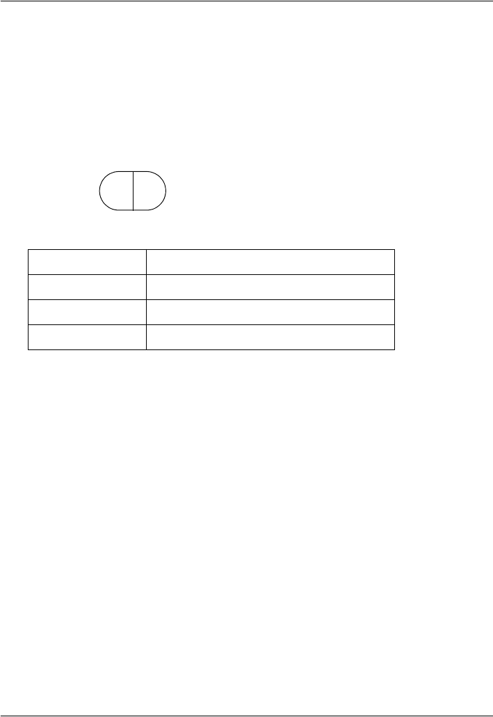
Guide light
Setting-out measurement etc. can be carried out effectively using the guide light. The guide light
is composed of a light that is divided into a red and a green light. A poleman can ascertain the
present position by checking the guide light color.
Guide light status
The guide light indicator is lit or flashes depending on the status of the guide light.
Laser radiation warning indicator
Laser radiation warning indicator is red when laser beam is emitted or laser-pointer is used,
allowing the status laser beam of the laser beam to be ascertained from the telescope eyepiece
side.
Peep sight
Use peep sight to aim the SRX in the direction of the measurement point.
Turn the instrument until the triangle in the peep sight is aligned with the target.
Instrument height mark
The height of the SRX is 236mm (from tribrach dish to this mark). "Instrument height" is input
when setting instrument station data and is the height from the measuring point (where SRX is
mounted) to this mark.
Trigger key
When the Trigger key is pressed SRX carries out the operation indicated by the softkey in bold
type on the screen. This allows the user to continue operation without having to return to the
display to press softkeys, making operations such as resection measurement even simpler.
Laser-pointer function
A target can be sighted with a red laser beam in dark locations without the use of the telescope.
Removing the handle (RC-TS3)
Light status Meaning
Red (From position of poleman) Move target left
Green (From position of poleman) Move target right
Red and Green Target is at correct horizontal position
green red
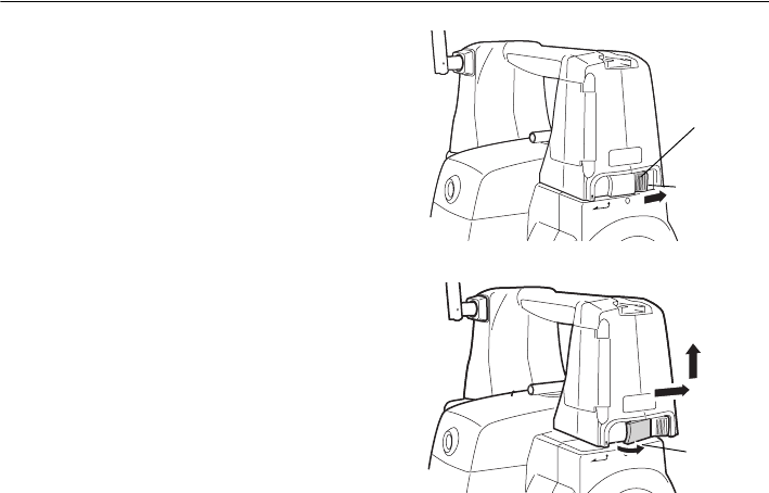
4. PRODUCT OUTLINE
12
1. Slide the handle locks in the direction as
shown at right until a click is heard. The
handle are now unlocked.
2. Pull the lock levers towards you and slide the
handle back and up to remove.
The handle lock levers, once released, will
return to the original position.
Make sure that the handle does not fall
while being removed. Removing the
handle requires a certain amount of force.
As a result, always hold firmly when
removing.
Handle
Green indicates
lock
locked state
Lock lever
13
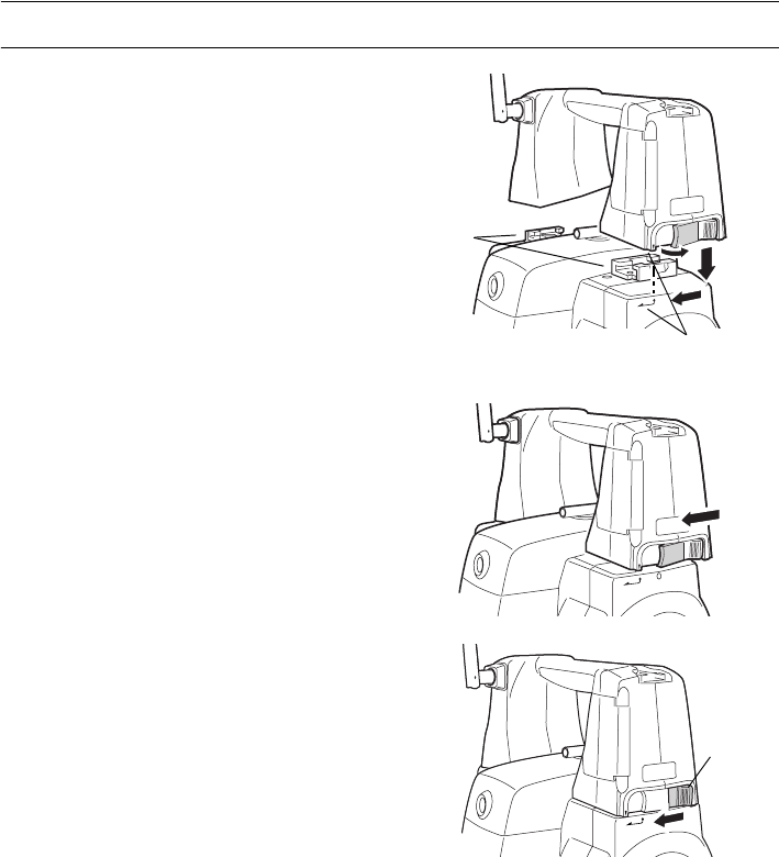
4. PRODUCT OUTLINE
Attaching the handle (RC-TS3)
1. Align the handle with the mounting brackets.
2. Slide the handle onto the mounting position
until a click is heard. Check that the handle
lock levers, once released, return to the closed
position.
3. Slide the handle locks away from you to lock
the handle. Check that the green sections of
the handle locks are showing.
• Securely lock the handle in place before
starting measurement.
Mounting
brackets
Handle mounting
position
Handle
locked
4. PRODUCT OUTLINE
14
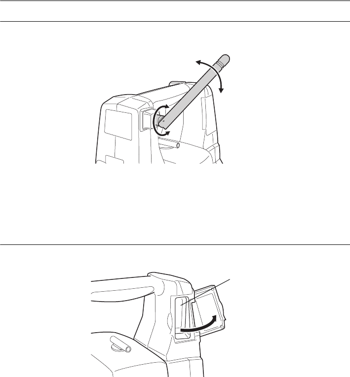
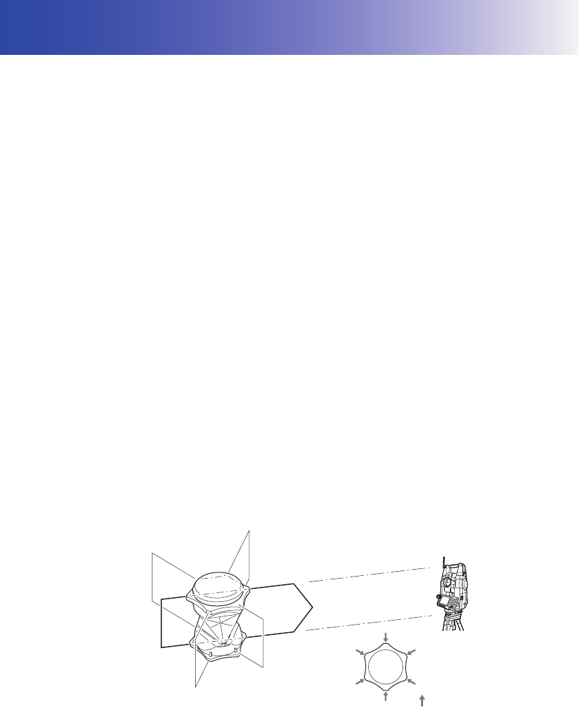
Bluetooth antenna
When performing communication using Bluetooth wireless technology, the antenna must be directed
towards the intended companion device.
Handle the antenna with care and be aware of the following points when operating.
• An extended antenna may be damaged if struck during operation.
• The antenna may be damaged if forcibly bent in an incorrect direction. The antenna cannot be bent
to angles exceeding 90°.
Beam detector for On-demand Remote Control System
Always open the beam detector cover when using the On-demand Remote Control system.
• The beam detector cover can be damaged if forced open beyond a certain angle. Always close the
beam detector cover before moving the instrument.
• Never touch the beam detector. The ability of the system to perform Turning may be adversely
affected.
Beam
detector
15
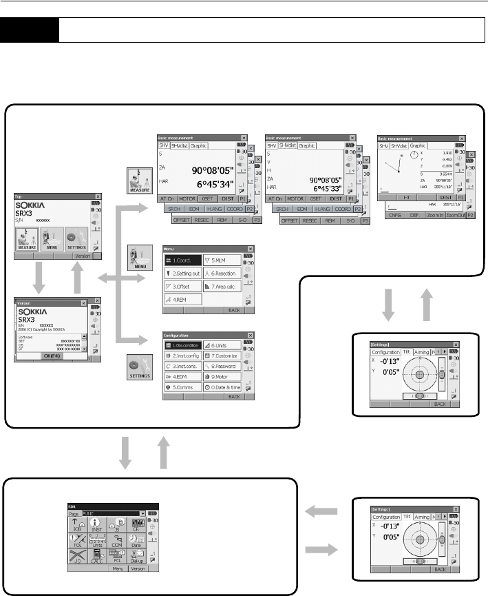
4. PRODUCT OUTLINE
The diagram below describes the different modes of the SRX and key operations for navigating
between them. Managing data functions are contained in Program mode (SDR).
• Switching between modes is not possible during distance measurement or while the motor is in
operation.
4.3 Mode Configuration
Basic mode
Status screen
[Version] [OK] {ESC}
Meas mode (Navigable with tabs)
Program mode
Settings mode
{SETTINGS}
SETTINGS mode
{PROGRAM}
Program mode (SDR)
"5.4 SETTINGS Mode"
{SETTINGS}
"5.2 Display Functions"
Chapters 15-20
Chapter 21
Series SRX SDR
Software Reference
Manual
4. PRODUCT OUTLINE
16
Precautions concerning Bluetooth wireless technology
• Use of this technology must be authorized according to telecommunications regulations of the
country where the instrument is being used. Contact your Sokkia agent in advance.
• Sokkia is not liable for the content of any transmission nor any content related thereto. When
communicating important data, run tests beforehand to ascertain that communication is operating
normally.
• Do not divulge the content of any transmission to any third party.
Radio interference when using Bluetooth technology
Bluetooth communication with the SRX uses the 2.4 GHz frequency band. This is the same band used
by industrial, scientific, and medical (ISM) equipment such as microwaves, portable premises radio
equipment (license required) and portable specified low-power radio equipment (license-exempt)
used in factory production lines, etc.
• Before starting transmission, check that operation will not take place within the vicinity of portable
premises radio equipment or specified low-power radio equipment.
• In the case that the instrument causes radio interference with portable premises radio equipment,
terminate the connection immediately and take measures to prevent further interference (e.g.
connect using an interface cable).
• In the case that the instrument causes radio interference with portable specified low-power radio
equipment, contact your Sokkia agent.
Although a radio station license is not required for this instrument, bear in mind the following points
when using Bluetooth technology for communication.
●Do not use within the vicinity of the following:
•Industrial, scientific, and medical (ISM) equipment such as microwaves and pacemakers.
• portable premises radio equipment (license required) used in factory production lines etc.
• portable specified low-power radio equipment (license-exempt)
•IEEE802.11b/IEEE802.11g standard wireless LAN devices
The above devices use the same frequency band as Bluetooth communications. As a result, using
the SRX within proximity to the above devices may result in interference causing communication
failure or reduction of transmission speed.
• Refrain from using the SRX within proximity to televisions and radios
Televisions and radios use a different frequency band to Bluetooth communications.
However, even if the SRX is used within proximity to the above equipment with no adverse effects with
regard to transmission, moving a Bluetooth-compatible device (including the SRX) closer to said
equipment may result in electronic noise in sound or images.
4.4 Bluetooth Wireless Technology

17
4. PRODUCT OUTLINE
Precautions regarding transmission
●For best results
•When using the On-demand Remote Control system, perform communication within a line-of-
sight distance of approximately 300m. The usable range becomes shorter when obstacles block
the line of sight, or devices other than the On-demand Remote Control system, such as PDAs or
computers, are used. Wood, glass and plastic will not impede
communication but the usable
range becomes shorter. Moreover, wood, glass and plastic containing metal frames, plates, foil
and other heat shielding elements as well as coatings containing metallic powders may adversely
affect Bluetooth communication and concrete, reinforced concrete, and metal will render it
impossible. Use a vinyl or plastic cover to protect the instrument from rain and moisture.
•The direction of the Bluetooth antenna can have adverse effects upon usable range. For best
results make sure that the antennas of both the SRX and the companion device are as vertical
as possible and visible to one another. When this is not possible, better results can be obtained
by pointing the antenna vertically towards the ground.
• Perform communication at a distance of 2m or more from electrical devices such as audio-visual
equipment and office automation equipment. In the case of microwave ovens, which are especially
susceptible to interference, this distance should be increased to 3m.
Moreover, operation near televisions and radios may lead to problems with reception.
• Ensure that cellular phones are at least 20cm from the SRX Bluetooth module during operation.
• Change location when proximity to a wireless device or broadcast station results in communication
failure.
When using the SRX near IEEE802.11b or IEEE802.11g standard wireless LAN devices or other
devices that operate on the 2.4GHz ISM band, interference may result, causing transmission speed
to slow or even disrupting the connection completely. Turn off all devices not being used.
●Reduced range due to atmospheric conditions
The radio waves used by the SRX may be absorbed or scattered by water and airborne moisture. The
signal may be weakened by exposure to rain, fog, and moisture from the human body with the limit of
usable range becoming much lower as a result. Moreover, as wireless devices lose signal strength
when close to the ground, perform communication at as high a position as possible.
18
5. BASIC OPERATION
Learn basic key operations here before you read each measurement procedure.
●Power ON/OFF
●Lighting up the reticle/keys and selecting screen backlight brightness
"21.2 Instrument Configuration"
●Switching to SETTINGS mode
"5.4 SETTINGS Mode"
●Switching to Program mode (SDR)
●Switching target type
"21.3 EDM Settings"
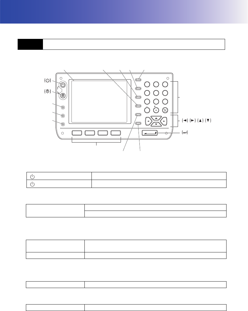
5.1 Basic Key Operation
Power ON
(while pressing) + {}Power OFF
{}Switches the reticle illumination/key backlight ON/OFF
Switches the screen backlight brightness setting
{SETTINGS} Switches to screens for tilt correction, returned signal checking,
motor operation, fixed velocity rotation,and general configuration
{SETTINGS}/{ESC} Returns to the previous screen (mode)
{PROGRAM} Switches between Basic mode and Program mode (SDR)
{TARGET} Switches between target types
PROGRAM
SETTINGS
TARGET
OFF
ESC
TAB
ENTER
F 1 F 2 F 3 F 4
SHIFT
BACKSPACE
FUNC CTRL
SPACE
ABC DEF GHI
PQR
YZ!VWX
JKL MNO
STU
#%@
789
456
1
0
23
?$
/&
{0} to {9}
{.} to {+/-}
Display {BACKSPACE} {TAB} {SHIFT} {ESC}
{FUNC CTRL}
{SPACE}
Softkey selection
{TARGET}
{PROGRAM}
{SETTINGS}
19
5. BASIC OPERATION
• Changes can also be made by tapping the status bar icon with the stylus pen.
"5.2 Display Functions"
●Switching the laser-pointer/guide light ON/OFF
Selecting laser-pointer/guide light after pressing {}: "21.3 EDM Settings"
•After turning ON the laser-pointer/guide light, the laser beam is emitted for 5 minutes, and then
automatically switches OFF.
• Changes can also be made by tapping the status bar icon with the stylus pen.
"5.2 Display Functions"
●Softkey operation
Softkeys are displayed on the bottom line of the screen.
●Inputting letters/figures
Character input method can be selected from upper case alphabetic, lower case alphabetic and
numeric characters.
•A selection can also be made by tapping the status bar icon with the stylus pen.
{} (Press and hold until
a beep sounds)
Turns the laser-pointer/guide light ON/OFF
{F1} to {F4} Select the function matching the softkeys
{FUNC CTRL} Toggles between softkey pages
{0} to {9} Input numeral or symbol printed above the key (during numeric
input mode)
Input alphabetic character in the order they are listed (in
alphabetic input mode)
{.} Input a decimal point (during numeric input mode)
{+/-} Input a plus or minus sign (during numeric input mode)
{ESC} Cancel the input data
{TAB} Shift to the next item
{BACKSPACE} Delete the character to the left
{SPACE} Input a blank space
{}/{}Move the cursor left/right during character input
{▲}/{▼}Move the cursor up/down during character input
{}Select/accept input word/value
5. BASIC OPERATION
20
●Selecting options
●Selecting tabs
●Other operation
Tabs:
"5.2 Display Functions"
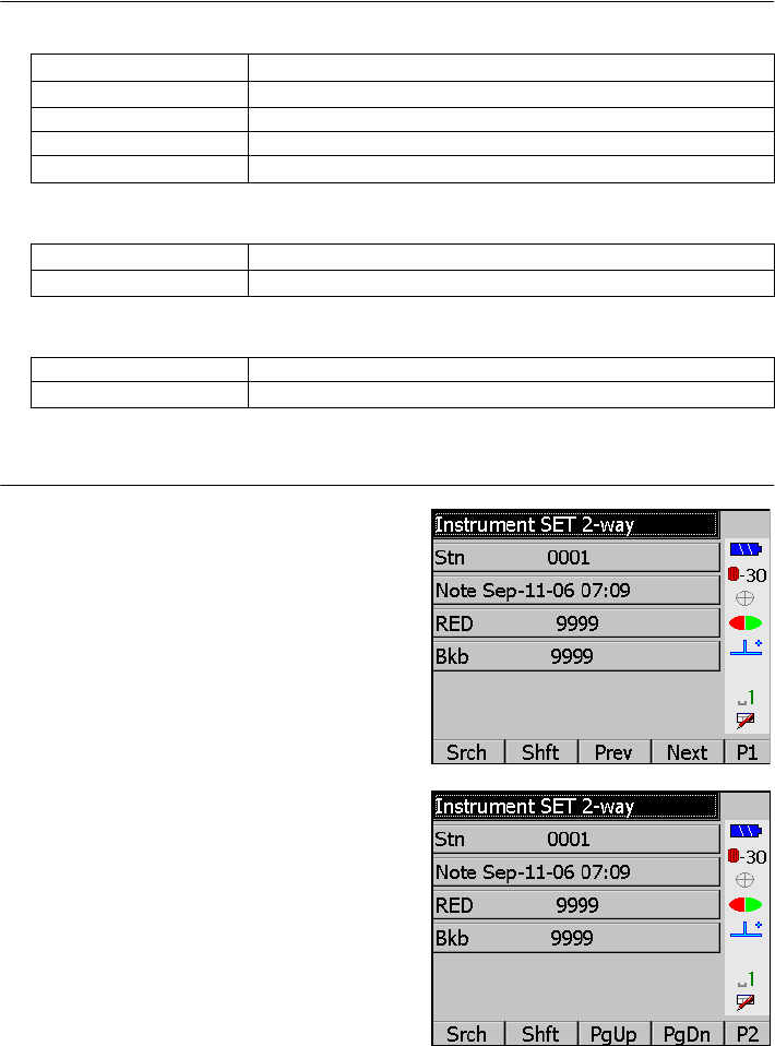
Example: Entering "computer" (lower case) as the name of a new device
1. Tap the input mode icon in the status bar (second
from bottom) until "_a" is displayed.
2. Press {7} three times.
"c" is displayed.
{▲}/{ ▼}Move the cursor/selection item up/down
{}/{}Move the cursor/selection item left/right or selects other option
{TAB} Shift to the next item
{SPACE} Display other options
{}Select/accept the option
{▲}/{ ▼}Move tab/cursor in tab up/down
{}/{}Display next tab at left/right
{ESC} Return to previous screen
{}/{}Moves tab left/right
21
5. BASIC OPERATION
3. Press {5} three times.
"o" is displayed.
4. Press {}.
Press {5} twice. "m" is displayed.
5. Continue to input letters. Press {} to
complete inputting.
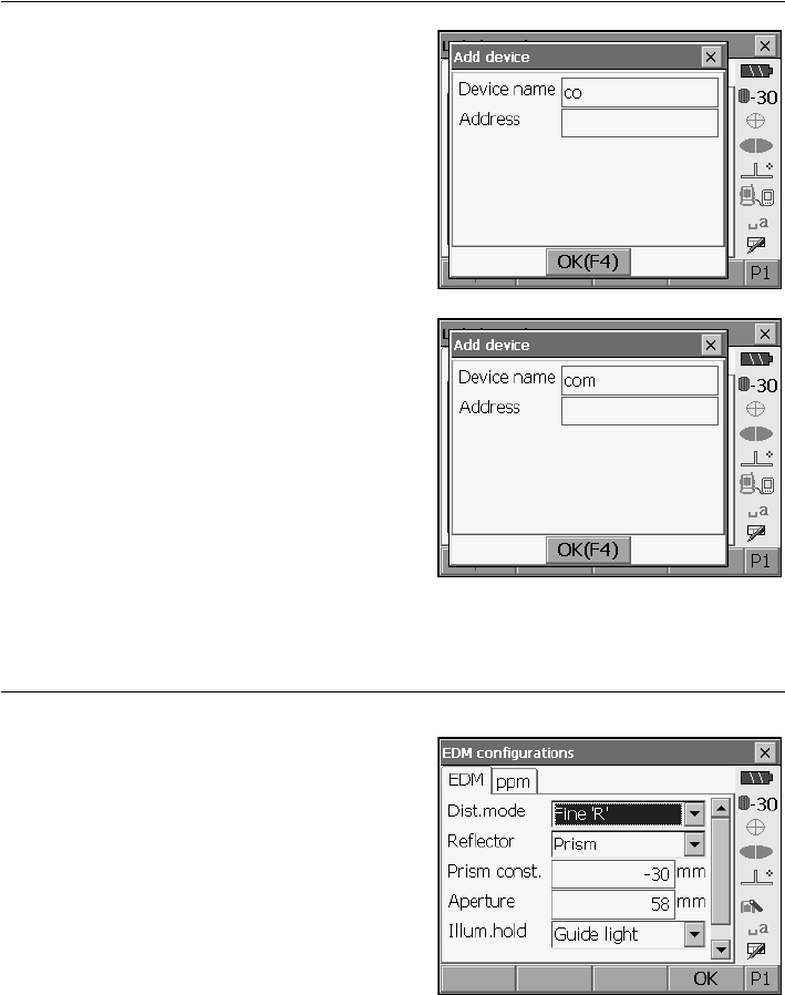
Example: selecting a reflector type
(Method 1)
1. Select
[EDM]
in the second page of Measure
mode or
"EDM" in SETTINGS mode.
2. Move to "Reflector" using {}/{}/{TAB}.
5. BASIC OPERATION
22
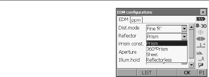
3. Press {SPACE} to display a list of all options.
4. Select an option using {}/{}.
5. Press {} to confirm selection.
(Method 2)
1. Select
[EDM]
in the second page of Measure
mode or
"EDM" in
SETTINGS mode.
2. Move to "Reflector" using {}/{}/{TAB}.
3. Switch between Prism, 360° Prism, Sheet, and
Reflectorless using {}/{}.
4. Press {} to confirm selection.
.
23
5. BASIC OPERATION
Screens can be selected/operated using the keys on the keyboard or the touch panel. The touch panel
can be operated using either the stylus pen provided or your fingers.
• Do not scratch the display or use any sharp implement other than the stylus pen to operate the
touch panel.
Using the stylus
The stylus pen can be used to select menus and buttons on the screen and operate the scroll bar. The
touch panel supports "tap", "double tap", and "drag" operations.
Displaying and operating screens
• To close a screen, tap the cross in the top right corner, or press {ESC}.
• Tabs, softkey allocations, displayed tab items, and character sizes can all be changed in
accordance with user preferences.
"21. CHANGING THE SETTINGS"
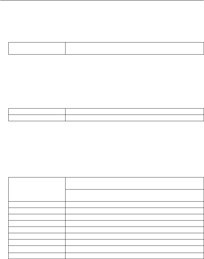
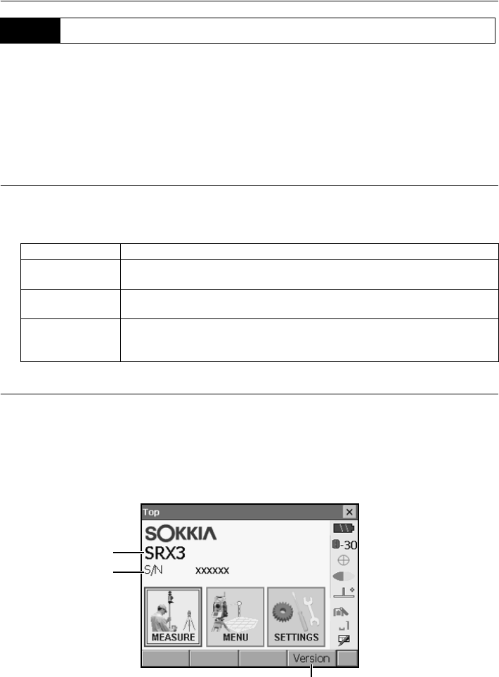
●Status screen
5.2 Display Functions
Operation Method
Tap Lightly tap the display once. This operation is equivalent to that of clicking
a mouse button when using a computer.
Double tap Lightly tap the display twice on the same point.This operation is equivalent
to the "double-click" for a computer mouse.
Drag Lightly apply the point of the stylus pen to the display and move in the
desired direction, maintaining contact between the stylus and display all
the time.
Instrument name
Serial No.
Application software version
5. BASIC OPERATION
24
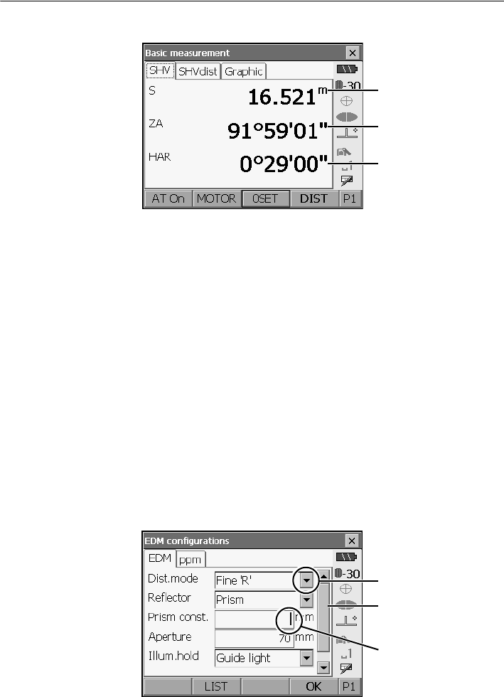
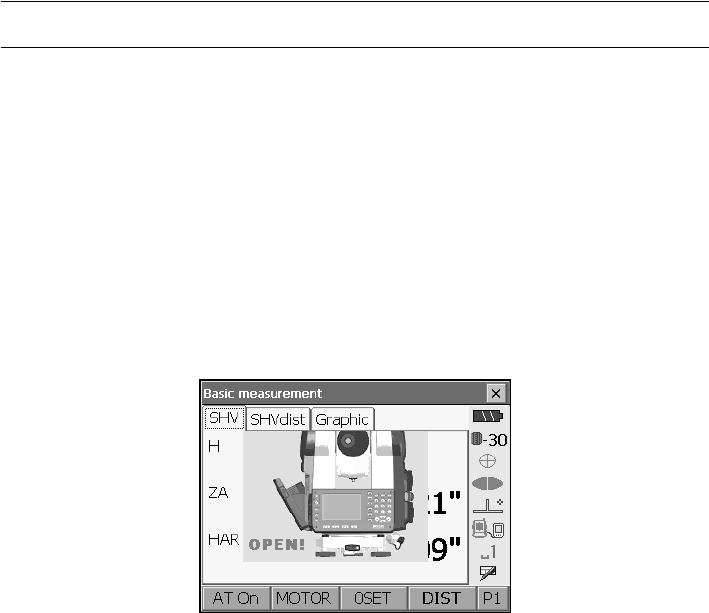
●Basic measurement screen
(1) Distance
Press [/SHV] to switch between the SHV and SHVdist tabs. An SHVdist tab will be created when
one does not exist.
"21.1 Observation Conditions"
"21.6 Allocating Key Functions"
(2) Vertical angle
The Vertical angle display can be switched between Zenith (Z=0°)/Horiz (H=0°)/Horiz (H=±90°)
To switch vertical angle/slope in %, press [ZA/%] when allocated to the Meas mode screen. The
capitalized letter in the softkey indicates the currently selected mode.
"21.1 Observation Conditions"
(3) Horizontal angle
Press [R/l] when allocated to the Meas mode screen to switch the display status. The capitalized
letter in the softkey indicates the currently selected mode.
HAR : Horizontal angle right
HAL : Horizontal angle left
"21.6 Allocating Key Functions"
●Input screen/configuration screen
(1) Distance
(2) Vertical angle
(3) Horizontal angle
Display all options
Scroll down for more
Values can be input/
items
edited
25
5. BASIC OPERATION
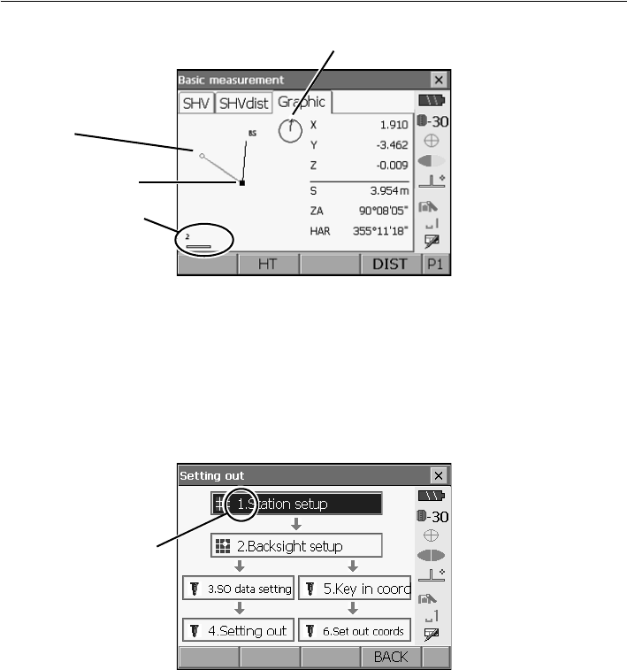
●Graphic tab
The Graphic tab display can be modified using the softkeys in the second page.
[CNFG]: In <Graphic configuration> the user can specify the orientation of the graphic tab
display and which point, target or station, to set at the center of the display.
[DEF.]: Returns to the original orientation display.
[ZoomIn]: Zooms in.
[ZoomOut]:Zooms out.
●Selecting menus
To select a menu, tap the touch panel or press the relevant number key.
Instrument station
Scale
(units: m)
Arrow indicates north
Target point
Number
5. BASIC OPERATION
26
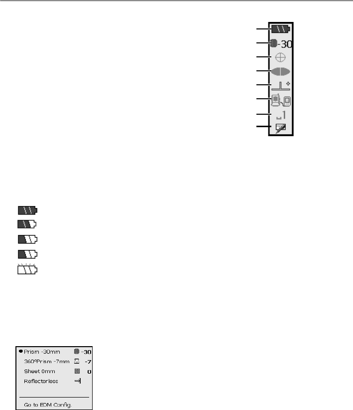
●Status bar
Indicates the current status of the instrument.
Tapping icons (1) to (7) will switch between the
relevant options for that item Tapping and holding
will display a list of all available options for that
item and, in certain cases, a link to the
configuration screen for that item.
Settings: "21. CHANGING THE SETTINGS"
(1)Remaining battery power
Remaining battery power indicator and configuration of auto-power function (BDC58/external
battery BDC61, Temperature = 25°, EDM on).
The remaining batter power displayed when distance measurement is in progress may differ to
that displayed at other times.
: Level 3 Full power
: Level 2 Plenty of power remains
: Level 1 Half or less power remains
Level 0 Little power remains. (Flashes red and black)
: No power (Red display in the center of the screen) Stop measurement and charge the
battery
"7. USING THE BATTERY"
(2) Target display
Selection of target type and configuration of prism constant.
: Prism (-30mm)
: 360° Prism (-7mm)
: Sheet (0mm)
: Reflectorless
Target information can be edited/recorded in <Reflector setting>.
"21.3 EDM Settings"
(1)
(2)
(3)
(4)
(5)
(6)
(7)
SIP code
27
5. BASIC OPERATION
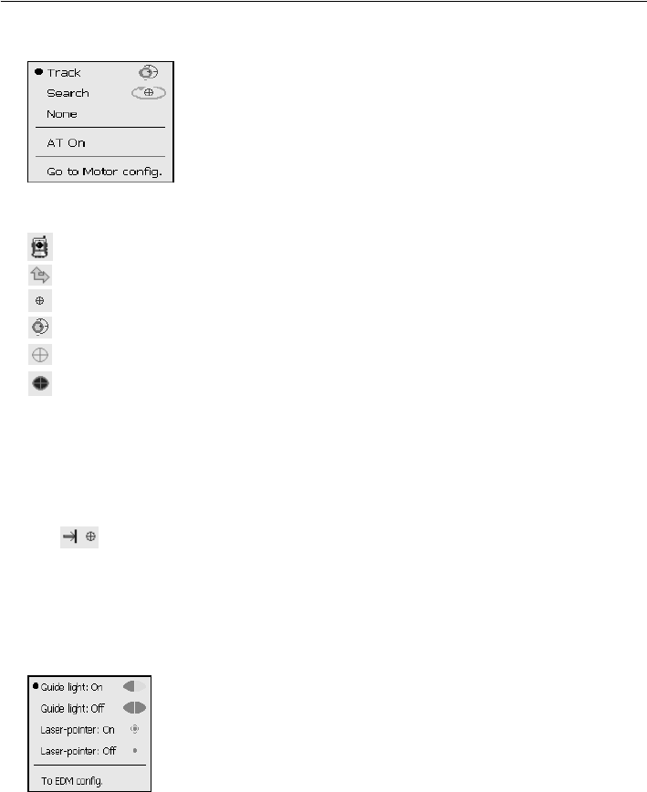
(3) Motor configuration
Configuration of Auto Pointing/Auto Tracking status.
: Auto Tracking ON
: Auto Pointing ON
: Both Auto Tracking and Auto Pointing OFF
: Start Auto Tracking."AT Off" is displayed when in "Prism wait"
status. Press to quit Auto Tracking.
One of the following icons will be displayed while the motor is in operation to indicate the current
status of the SRX.
: Rotating
: Rotating at fixed velocity
: Searching
: Auto Tracking in progress (when Auto Tracking set)
: Target lost (when Auto Tracking set)
: (Flashes red) Waiting for prism (when Auto Tracking set)
Motor settings: "11.1 Auto Pointing Settings", "12.1 Auto Tracking Settings"
• Auto Tracking and Auto Pointing cannot be performed when "Reflectorless" has been selected as
the target type. Auto Tracking cannot be performed when "Sheet" has been selected as the target
type. will be displayed.
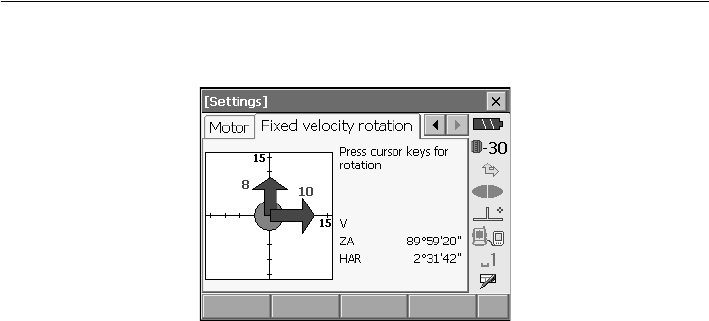
• An arrow indicating turn direction will be displayed when the SRX is rotating at a fixed velocity.
Fixed velocity rotation: "5.4 SETTINGS Mode ● Fixed velocity rotation"
(4) Laser-pointer/guide light
Configuration of laser-pointer/guide light status.
Switching the laser-pointer/guide light ON/OFF: "5.1 Basic Key Operation"
: Guide light ON
: Guide light OFF
: Laser-pointer ON
: Laser-pointer OFF
• The laser-pointer will be automatically switched OFF during distance measurement.
5. BASIC OPERATION
28
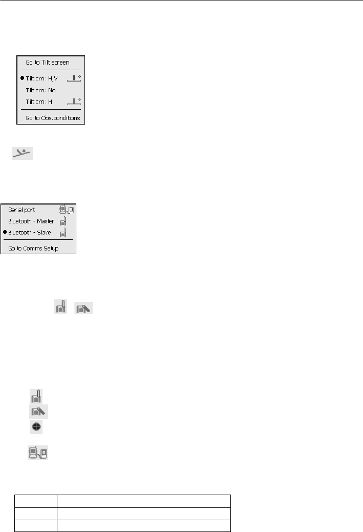
(5) Tilt angle compensation
The vertical and horizontal angles are automatically compensated for small tilt errors usng the
SRX's dual-axis tilt sensor. This icon displays the status of this function.
: Horizontal and vertical tilt angles compensated (blue)
: No compensation
: Only horizontal tilt angle compensated (green)
• is displayed when the instrument is out of level.
(6) Communication status
Selection and configuration of communication status with external devices. This icon is not
displayed in Program mode (SDR).
: Connection via RS-232C cable
: Connection via Bluetooth (SRX set as "Master" device) (blue antenna)
: Connection via Bluetooth (SRX set as "Slave" device) (green antenna)
• When Bluetooth is selected (SRX set as "Master" device) a connection can be initiated/canceled
by tapping / .
• An arrow symbol is displayed while data is being transmitted.
• This icon is not displayed in Program mode (SDR).
Connection status is displayed as follows.
i) Connection via Bluetooth
When SRX is set as the "Master" device the antenna mark is blue. When the SRX is set as the
"Slave" device the antenna mark is green.
: Connecting
: Cancelling connection
: Inquiring about other Bluetooth devices (only when SRX is set as "Master" device)
ii) : Connection via RS-232C cable
(7) Input mode
Selection of input mode
_1 Inputting numbers and symbols
_A Inputting upper case alphabetic characters
_a Inputting lower case alphabetic characters
29
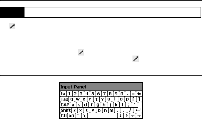
5. BASIC OPERATION
Tap to display <Input Panel>. This keyboard can be used to input numeric and alphabetic
characters as well as symbols. Tap the icon again to close.
• When <Input panel> is covering the icon of the status bar, use the stylus pen to drag the input
panel to another part of the screen so that you can access the icon.
Input panel
Esc : Deletes all input characters
Tab : Moves the cursor to the next text box
CAP :Alternates between upper and lower case alphabetic characters and numbers/
symbols
Shift :Alternates between upper and lower case alphabetic characters and numbers/
symbols. Is canceled after inputting a single character.
Ctl :No function
Del/A: Delete the character to the left/right or deletes the entire text in the active section
←→ :Move the cursor left/right
: Accept input characters
Space : Input a blank space
áü :Accesses further Latin/Germanic characters/symbols
5.3 Inputting Characters using SIP Code (Input Panel)
5. BASIC OPERATION
30
Press {SETTINGS} to switch to screens for tilt correction, returned signal checking, motor operation,
fixed velocity rotation,and general configuration
Performing settings: "21. CHANGING THE SETTINGS", Tilt settings: "9.2 Levelling", Returned
signal checking: "14.1 Returned Signal Checking"
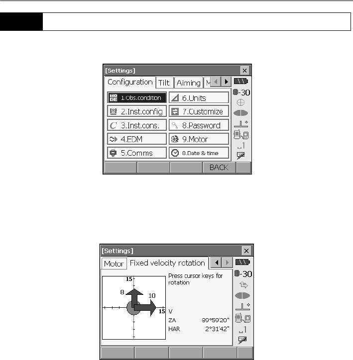
●Motor settings
The instrument can be automatically rotated to a desired vertical and/or horizontal angle by
specifying the angle in the "Motor" tab and selecting [ROTATE].
• The following operations can be performed using the softkeys in the second page.
[READ] : Read in coordinates from Program mode (SDR) and set as the desired angle.
[COORD] : Specify rotation angle by inputting coordinates in <Key in coord>.
[TURN] : Rotate the SRX 180°.
[CNFG] : Perform Motor configuration settings. "12.1 Auto Tracking Settings"
5.4 SETTINGS Mode
31
5. BASIC OPERATION
●Fixed velocity rotation
The SRX horizontal angle and telescope can be rotated using the controls in the Fixed velocity
rotation tab. Speed settings are from 1 to 16.
Tap the touch panel in the desired rotation direction.
Press {ESC} or tap the red center circle to stop rotation.
32
6. USING THE CF CARD SLOT
CF (Compact Flash) cards, for saving surveying and other data, are supported by the SRX. However,
users with SD cards will need to use an CF card slot adapter.
Management of JOB and survey data is done in Program mode (SDR).
Series SRX SDR Software Reference Manual
• Contact your Sokkia agent for details regarding communication formats for CF card input/output.
• Data can also be transferred to an external device for storage and/or editing using the SRX’s US
B
ports.
"8. CONNECTING TO EXTERNAL DEVICES"
• Do not remove the CF card during data read/write.
• Make sure the eject button is fully depressed when a CF card is inserted. A protruding eject button
will be depressed when the card cover is closed causing the card to be ejected.
• Always close the card cover before moving the instrument. The card cover can be damaged if
forced open beyond a certain angle.
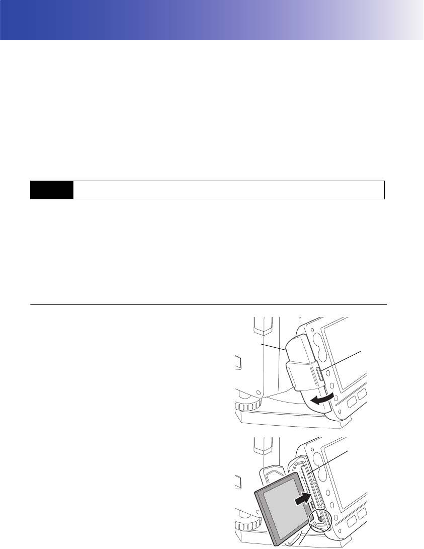
PROCEDURE Inserting the CF card
1. Push the catch on the card cover to open.
2. Insert the CF card until a click is heard.
3. Close the card cover.
6.1 Inserting/Removing the CF Card
Catch
Card cover
Card
slot
Eject button
33
6. USING THE CF CARD SLOT
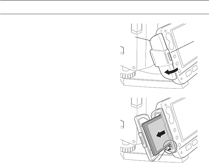
PROCEDURE Removing the CF card
1. Push the catch on the card cover to open.
2. Press the eject button once to release. Once
the eject button is fully protruded, press once
more to remove the card from the card slot.
3. Close the card cover.
Catch
Card cover
Eject button
34
7. USING THE BATTERY
Mount the charged battery (BDC58).
Types of power source: "24. POWER SUPPLY SYSTEM"
• Remove the battery when the instrument is not being used.
• Before removing the battery, turn off the power to the instrument. If the battery is removed while
the power is switched on, a warm boot occurs. File and folder data may be lost as a result.
• When installing/removing the battery, make sure that moisture or dust particles do not come in
contact with the inside of the instrument.
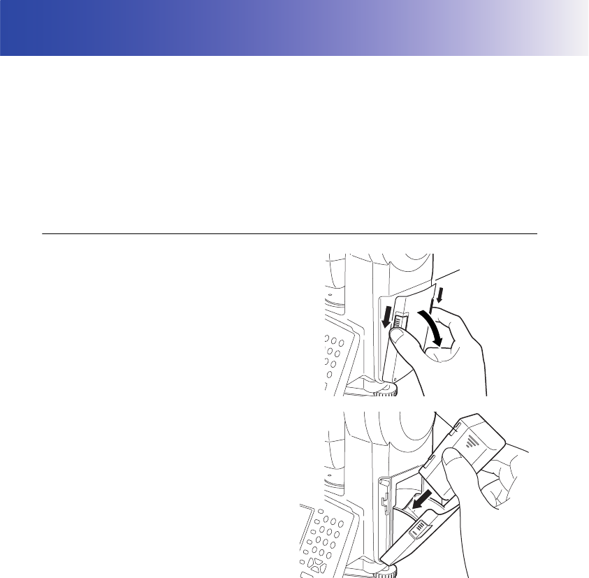
PROCEDURE Mounting the battery
1. Slide down the catches on the battery cover to
open.
2. Insert the battery in the direction of the arrow
printed on the side.
3. Close the battery cover. A click is heard when
the cover is secure.
Battery cover
Battery
35
7. USING THE BATTERY
PROCEDURE Removing the battery
1. Slide down the catches on the battery cover to
open.
2. Retract the battery.
3. Close the battery cover. A click is heard when
the cover is secure.
• Battery cover
If the battery cover is open during power ON, SRX notifies you by displaying the screen below and
beeping.
• When the battery cover is closed, the previous screen is restored.

36
8. CONNECTING TO EXTERNAL DEVICES
The SRX supports both USB and Bluetooth wireless technology for communication with data
collectors, computers, cellular phones, and the On-demand Remote Control system.
Read this manual in conjunction with the operator’s manual for the relevant external device.
Bluetooth communication: "4.4 Bluetooth Wireless Technology"
Transferring data using the SFX function: SFX Dial-Up Program Explanations, Output
format and command operations: Interfacing with the SOKKIA SDR Electronic Field
Book and Command Explanations manuals
The Bluetooth module incorporated in the SRX can be used for communication with Bluetooth devices
other than the SRX.
Security functions such as Bluetooth device address and passkey can be used to provide a level of
protection for wireless communication.
Bluetooth device address
This is a number unique to one particular Bluetooth device used to identify devices during
communication. This number consists of 12 characters (numbers 0 to 9 and letters from A to F).
Some devices may be referred to by their Bluetooth device address.
SRX Bluetooth antenna: "4.2 Parts of the Instrument Bluetooth antenna"
Bluetooth connections
Communication between a pair of Bluetooth devices requires one device to be set as the
"Master" and the other as the "Slave". To initiate connections from the SRX side, set the SRX
as the "Master" device. To initiate connections from the paired device side, set the SRX as the
"Slave" device. The factory setting is "Slave".
8.1 Wireless Communication using Bluetooth Technology
37
8. CONNECTING TO EXTERNAL DEVICES
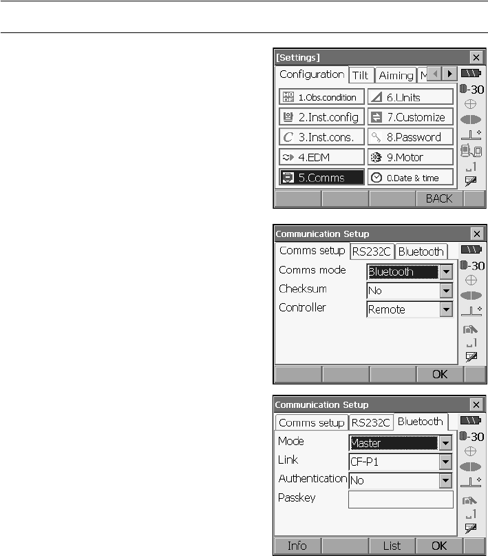
PROCEDURE Necessary settings for Bluetooth communication
1. Select "Comms" in SETTINGS mode. Set Comms
mode in the Comms setup tab to "Bluetooth".
2. Select a mode for the SRX in the Bluetooth tab.
To initiate connections from the SRX side, set the
SRX as the "Master" device. To initiate
connections from the paired device side, set the
SRX as "Slave".
The factory setting is "Slave".
Register companion devices.
•"Master" cannot be selected when no companion
devices have been registered.
3. Select, in "Link", a companion device from among
the Bluetooth devices already registered in the
SRX.
Registering devices: "PROCEDURE
Registering Bluetooth companion devices"
•Companion devices cannot be selected when the
SRX is set as "Slave".
4. Set "Authentication" to "Yes" or "No".

8. CONNECTING TO EXTERNAL DEVICES
38
5. When "Authentication" is set to "Yes", input the
same passkey as that for the intended companion
device. Even if "Authentication" is set to "No", a
passkey is requested when authentication is set
on the companion device being used.
• Up to 16 numeral characters can be input. Input
characters will be displayed as asterisks (e.g.
"*****"). The passkey was set to "0123" at the
factory.
6. Press [OK] to finish settings.
39
8. CONNECTING TO EXTERNAL DEVICES
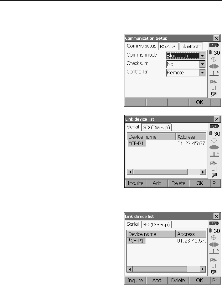
PROCEDURE Registering Bluetooth companion devices
1. Power on the companion device.
2. Select "Comms" in SETTINGS mode.
3. Select "Link" in the Bluetooth tab. and press
[LIST] to display a list of all registered devices.
Data collector devices can be set in the Serial tab
and devices for use with the SFX Dial-Up Program
in the SFX (Dial-Up) tab.
4. Register your Bluetooth device(s).
Press
[Add]
to display <Add device>. Input the
device name and Bluetooth address and press
[OK]
. Up to 12 hexadecimal digits can be input.
8. CONNECTING TO EXTERNAL DEVICES
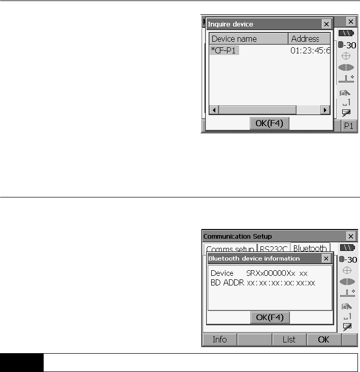
40
Press [Inquire] to inquire about Bluetooth devices
in the immediate vicinity of the SRX and display
their device name and address in a list. Select a
device from this list and press [OK] to add to the
Link device list in step 3.
Press [Delete] to delete the selected device
name. Deleted device names cannot be retrieved.
• Select a device and press
[Edit]
in the second
page
to update the device name and/or device
address.
5. Press [OK] to complete registration and return to
the screen in step 2.
PROCEDURE Displaying Bluetooth information for the SRX
1. Select "Comms" in SETTINGS mode.
2. Press [Info] in the Bluetooth tab to display the
device name and Bluetooth address for the SRX
Bluetooth module. Register the Bluetooth address
displayed here in the paired device.
• Bluetooth communication causes SRX battery power to be depleted at a higher than average rate.
Under the "Slave" setting, the SRX is constantly being searched for by communicable devices and
therefore consumes an ever greater amount of power.
• Check that the companion device (data collector, computer, cellular phone, or On-demand Remote
Control system etc.) is turned on and the relevant Bluetooth settings are complete.
• All communication settings will be changed to factory settings when a cold boot is performed.
Comms setup will need to be performed again.
"8.1 Wireless Communication using Bluetooth Technology"
8.2 Communication between the SRX and Companion Device
41
8. CONNECTING TO EXTERNAL DEVICES
1. Complete the necessary SRX settings for
Bluetooth communication.
"8.1 Wireless Communication using
Bluetooth Technology"
• To initiate connections from the SRX side, set
SRX as the "Master" device. To initiate
connections from the paired device side, set
SRX as "Slave".
2. Start communication
When SRX is set as the "Master" device, the
[Connect]
softkey is allocated to the fourth page
of Meas mode. When
[Connect]
is pressed the
SRX searches for the device selected in "Link"
and a connection starts. When a connection has
been successfully established is displayed
in the status bar.
• When SRX is set as the "Slave" device, the establishing of a connection can only be initiated/
canceled by the companion device set as "Master".
• The establishing of a connection can also be initiated by tapping in the status bar.
Status bar, communication status:
"5.2 Display Functions"
3. Press [Cancel] in the fourth page of Meas mode
to terminate the connection.
• A connection can also be terminated by tapping in the status bar.
8. CONNECTING TO EXTERNAL DEVICES
42
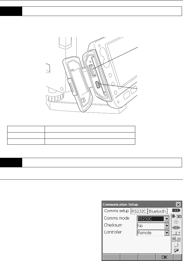
SRX has two different USB ports.Sokkia cannot guarantee that all USB devices are compatible with
the SRX USB ports.
Each port is used for connection to different types of devices.
PROCEDURE Basic cable settings
1. Connect the cable.
Cables: "27. OPTIONAL ACCESSORIES"
2. Select "Comms" in SETTINGS mode.
Set communication conditions in the Comms
setup tab.Set "Comms mode" to "RS232C".
8.3 Connecting to USB devices
Port name Device type
USB port 1 USB memory devices etc.
USB port 2 computers etc.
8.4 Connection via RS-232C cable
USB port 1
USB port 2
43
8. CONNECTING TO EXTERNAL DEVICES
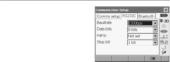
3. Set options in the RS232C tab according to the
selection made in the Comms setup tab.
*: factory settings
Baud rate:
1200*/2400/4800/9600/19200/38400bps
Data bits: 8*/7 bits
Parity: Not set*/Odd/Even
Stop bit: 1*/ 2 bits
44
9. SETTING UP THE INSTRUMENT
• Mount the battery in the instrument before performing this operation because the instrument will tilt
slightly if the battery is mounted after levelling.
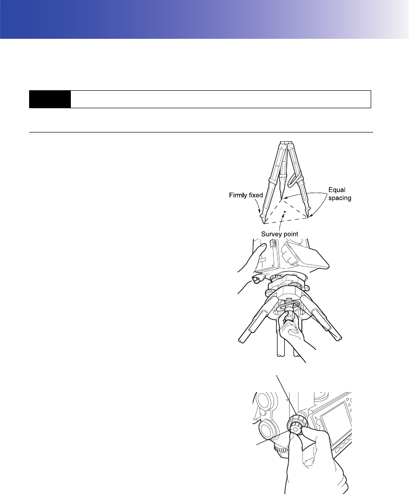
PROCEDURE
1. Set up the tripod
Make sure the legs are spaced at equal intervals
and the head is approximately level.
Set the tripod so that the head is positioned over
the surveying point.
Make sure the tripod shoes are firmly fixed in the
ground.
2. Place the instrument on the tripod head.
Supporting it with one hand, tighten the centering
screw on the bottom of the unit to make sure it is
secured to the tripod.
3. Looking through the optical plummet eyepiece,
turn the optical plummet eyepiece to focus on
the reticle.
Turn the optical plummet focusing ring to focus
on the surveying point.
9.1 Centering
Centering screw
Focussing on the survey point
Focussing on
the reticle
45
9. SETTING UP THE INSTRUMENT
Instrument can be levelled using the screen.
“ Levelling on the screen”
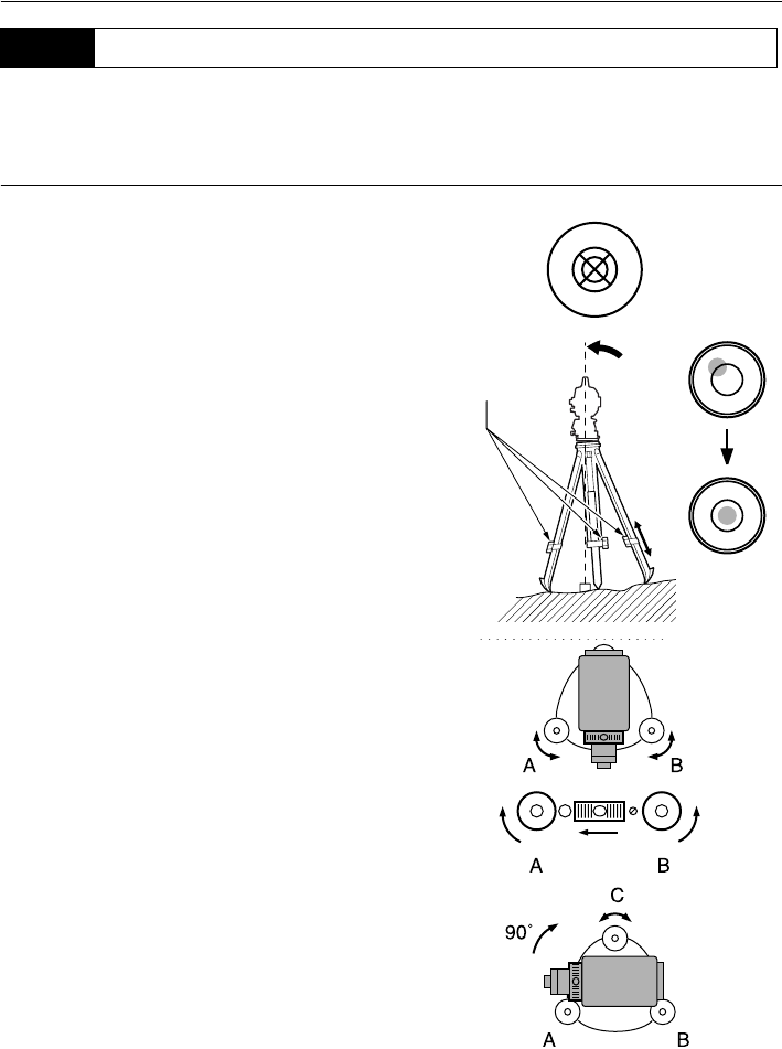
PROCEDURE
1. Adjust the levelling foot screws to center the
surveying point in the optical plummet reticle.
2. Center the bubble in the circular level by either
shortening the tripod leg closest to the offcenter
direction of the bubble or by lengthening the
tripod leg farthest from the offcenter direction of
the bubble. Adjust one more tripod leg to center
the bubble.
3. Turn the upper part of the instrument until the
plate level is parallel to a line between levelling
foot screws A and B.
Center the air bubble using levelling foot screws
A and B.
The bubble moves towards a clockwise rotated
levelling foot screw.
4. Turn the upper part of the instrument though
90°.
The plate level is now perpendicular to a line
between levelling foot screws A and B.
Center the air bubble using levelling foot screw
C.
9.2 Levelling
Tripod legs
adjustment
9. SETTING UP THE INSTRUMENT
46
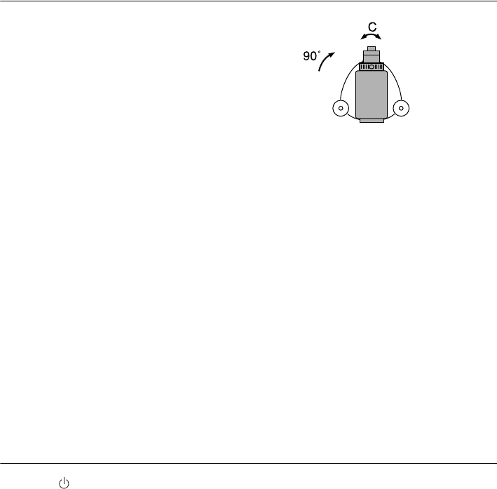
5. Turn another 90° and check bubble position
Turn the upper part of the instrument a further
90° and check to see if the bubble is still in the
center of the plate level. If the bubble is off-
center, perform the following:
a.Turn levelling foot screws A and B equally in
opposite directions to remove half of the
bubble displacement.
b.Turn the upper part a further 90°, and use
levelling foot screw C to remove half of the
displacement in this direction.
Or adjust the plate level.
.
"23.1 Plate Level"
6. Turn the instrument and check to see if the air
bubble is in the same position in all directions.
If it is not, repeat the levelling procedure.
7. Loosen the centering screw slightly.
Looking through the optical plummet eyepiece,
slide the instrument over the tripod head until the
surveying point is exactly centered in the reticle.
Retighten the centering screw securely.
8. Check again to make sure the bubble in the
plate level is centered
If not, repeat the procedure starting from step 3.
PROCEDURE Levelling on the screen
1. Press {} to power on.
"10. POWER ON/OFF"
2. Press {SETTINGS} to enter SETTINGS mode.
47
9. SETTING UP THE INSTRUMENT
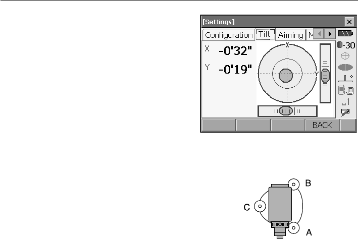
3. Select the Tilt tab to display the circular level on
the screen.
“z” indicates the bubble in circular level. The
range of the inside circle is ±3' and the range of the
outside circle is ±4.5'.
4. Center “z” in the circular level.
"9.2 Levelling" steps 1 to 2
5. Turn the instrument until the telescope is parallel
to a line between levelling foot screws A and B.
6. Set the tilt angle to 0° using foot screws A and B
for the X direction and levelling screw C for the Y
direction.
7. Press {ESC} to return to Meas mode.

48
10.POWER ON/OFF
PROCEDURE Power ON
1. Press .
When the power is switched on, a self-check is run.
The Meas mode screen is displayed.
If "Out of range" is displayed, the instrument tilt
sensor is indicating that the instrument is out of level.
Level the instrument once again and the horizontal
and vertical angles will be displayed.
• "Tilt crn." in "Obs. condition" should be set to "No" if the display is unsteady due to vibration or strong
wind.
"21.1 Observation Conditions"
Resume function
The Resume function redisplays the screen appearing before the instrument was powered OFF
when the instrument is powered back ON. All parameter settings are also saved. Even if
remaining battery power is completely depleted, this function will remain active for 1 minute,
after which it is canceled. Replace a depleted battery as soon as possible.
PROCEDURE Power OFF
Press {} while pressing {}.
• When there is almost no battery power remaining,
the battery mark in the status bar will start to
blink.In this event, stop measurement, switch off
the power and charge the battery or replace with a
fully charged battery.
• To save power, power to the SRX is automatically
cut off if it is not operated for a fixed period of time.
This time period can be set in "Power off" in
<Inst.config.>.
"21.2 Instrument Configuration"
49
10. POWER ON/OFF
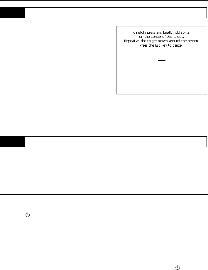
When using for the first time, or after performing a cold
boot, the screen for configuring the touch panel will be
displayed.
Follow the instructions on the screen. Tap the cross-
hairs at the center of the display with the stylus pen.
Tap 5 times. Press {} to complete touch panel
configuration. Press {ESC} to retain previous settings.
For units with a display on both the F1 and F2 faces:
After tapping 5 times the display backlight wi
ll
dim and the display on the reverse face will
illuminate. Tap the cross-hairs on the reverse
fac
e display a further 5 times.
• Touch panel configuration can be performed at any time by pressing [PNL CAL] in <Inst.config.>.
Reset: "10.2 Resolving Software Issues"
If you are experiencing problems with the SRX and suspect a fault in the program, you should try a
warm boot. A warm boot will not erase surveying data in Program mode (SDR) but will cancel the
resume function. Whenever possible transmit the data to a personal computer before rebooting.
If the problem is not resolved with a warm boot the next step is to perform a cold boot.
PROCEDURE
1. Power OFF the instrument.
2. Press { } while pressing {}.
The instrument is reset and powers ON as normal.
Cold boot
If the problem is not resolved with a warm boot the next step is to perform a cold boot. A cold
boot will not erase surveying data in Program mode (SDR) but all the parameters will be
changed to the factory settings. If the data in the memory is necessary, BE SURE TO
TRANSFER IT TO A PERSONAL COMPUTER BEFORE PERFORMING A COLD BOOT.
To perform a cold boot, while holding {F3}, {F1}, and {BACKSPACE}, press
{}
.
The instrument is reset and powers ON as normal.
"21.10 Restoring Default Settings"
Problems Powering OFF
10.1 Configuring the Touch Panel
10.2 Resolving Software Issues
10. POWER ON/OFF
50
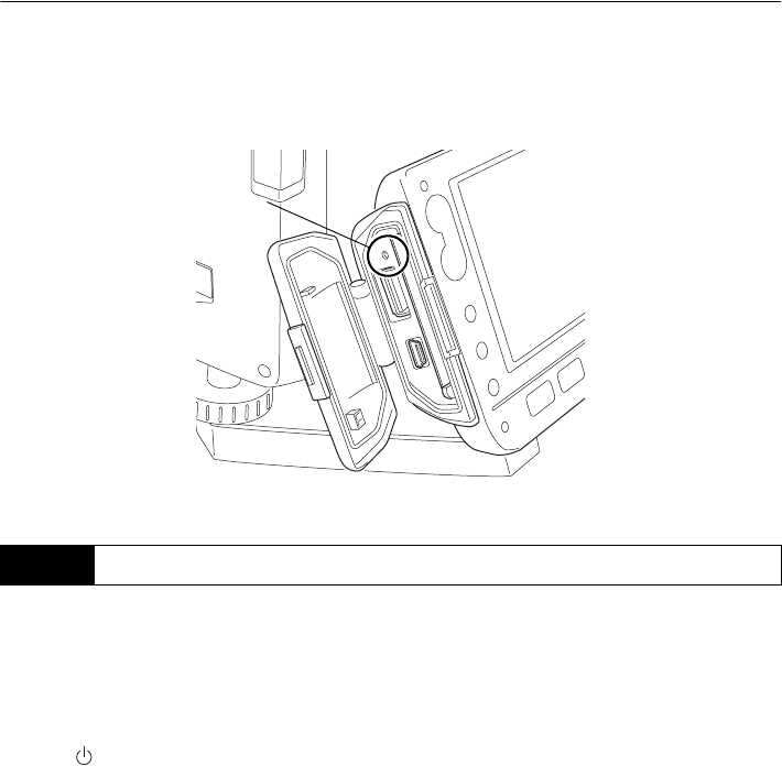
When the instrument cannot be powered OFF as normal, depress the reset button with the tip
of the stylus pen. Then, power ON as normal.
•Do not press the reset button while accessing programs. File and folder data may be lost as a
result.
The SRX can be powered ON/OFF from an external device such as a computer or control terminal.
When the SRX is powered OFF from a paired
Bluetooth device during Bluetooth communication, the
screen shown at right will be displayed.
Powering ON the SRX from the paired device or by
pressing on the SRX itself redisplays the screen
appearing before the instrument was powered OFF.
Powering OFF the SRX during Bluetooth
communication will cancel the Bluetooth connection. If
this screen is displayed continuously for 30 minutes,
power to the SRX is automatically cut off.
"12.1 Auto Tracking Settings"
10.3 Powering the SRX ON/OFF from an External Instrument
Reset button
51
11.TARGET SIGHTING
The target can be automatically sighted using the Auto Pointing function or manually sighted by the
operator using the peep sight and telescope. The Auto Pointing function automatically sights the target
and does not require you to focus the telescope. The SRX analyses the image of the prism in the field
of view and moves the telescope to sight the center of this prism.
•The search method can be set.
"12.1 Auto Tracking Settings"
Caution
• The instrument emits a laser beam until the center of the prism is sighted.
• Auto Pointing can only be performed when a prism or sheet is used as the target. For reflectorless
measurement, the target must be sighted manually.
• Use reflective prisms/reflective sheets from Sokkia for higher precision measurement.
• Auto Pointing cannot be performed if the prism is located at the zenith. In this case, manually sight
the target.
"11.3 Manually Sighting the Target"
• If more than one prism is located in the field of sight during Auto Pointing, an operation error will
occur and the SRX will not be able to find the target.
• A prism beyond glass cannot be searched because a measurement error occurs.
• If an obstacle blocks the laser beam path between the SRX and the prism, SRX cannot find the
target correctly.
• If strong light shines directly into the objective lens, measurement cannot be performed correctly.
• Position the prism in alignment with the objective lens. In short distance measurement especially,
make sure to align the prism with the objective lens (within 10 to 15°) to obtain the correct result. A
prism with a prism constant of -40mm can eliminate the error caused by tilted prism.
Aspect of the 360° Prism
The 360° Prism should be set up so that a pair of hexagonal points on the rubber flanges of the
prism are aligned with the sighting direction of the SRX (see the diagram below).
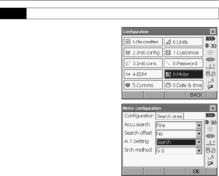
11. TARGET SIGHTING
52
1. Select "Motor" in <Configuration>.
Set Auto Pointing functions in the Configuration
tab.
Set "A.T. Setting" to "Search".
Settings and Options
(*: factory settings)
(1) Accu. search
Fine*/Rapid
(2) A.T. Setting
None/Search*/Track
(3) Srch method
G.S.*/R.C.
Accu. search
Compared to Digital Imaging Mode ("Rapid" setting), the analysis of the prism image in Optical
Imaging Mode ("Fine" setting) is finer and the criteria for completing sighting are more stringent.
"Rapid" mode should be used when supporting the pole by hand if "Time out" is displayed before
the SRX completes sighting as a result of vibration, or, completing Auto Pointing takes too long.
Srch method
Selects search before distance measurement option.
When set to "G.S." the SRX will search for the target in the area specified in the Search area
tab. When set to "R.C.", the SRX will wait for a Turning command to be issued from the RC
Controller before starting Auto Pointing. Both methods can be used to sight the target.
11.1 Auto Pointing Settings
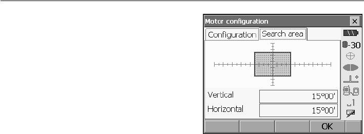
53
11. TARGET SIGHTING
2. Set the area in which to perform target sighting in
the Search area tab. Drag the box to specify the
desired or area or input vertical and horizontal
angle values.
Angle values can only be specified in 1°30’ steps
(e.g. 15°00’, 16°30’, 18°00’ etc.). Input values not
conforming to this format will be automatically
rounded up.
3. Press [OK].
11. TARGET SIGHTING
54
PROCEDURE
1. Use the peep sight to aim the objective lens in the
general direction of the target. The vertical and
horizontal jogging knobs can be used for precise
adjustments of the instrument and telescope.
2. Select [SRCH] in any Meas mode screen. The
telescope and top half of the instrument rotate
and target auto-search begins. When the target is
found, the instrument sights the center of the
prism and stops.
Allocating the
[SRCH]
softkey:
"21.6 Allocating Key Functions"
• The following softkeys can also be used for Auto Pointing when "A.T. Setting" in <Motor
configuration> is set to "Search".
Motor settings: "12.1 Auto Tracking Settings"
11.2 Auto-Pointing Function for Target Sighting
Softkey Function
[DIST] Performs Auto Pointing then distance and angle measurement
[SRCH] Performs Auto Pointing then distance and angle measurement
[H.ANG] Performs Auto Pointing then sets current angle to the specified angle
[0 SET] Performs Auto Pointing then sets current angle to 0
[RC] Rotates in the direction specified by the On-demand Remote Control
system then performs Auto Pointing
[<-RC] Rotates in a counterclockwise direction (from the point of view of the
RC Controller) then performs Auto Pointing
[RC->] Rotates in a clockwise direction (from the point of view of the RC
Controller) then performs Auto Pointing
[ROTATE] Automatically rotates the instrument to the specified vertical and
horizontal angles then performs Auto Pointing
[TURN] Rotates the SRX 180
°
then performs Auto Pointing
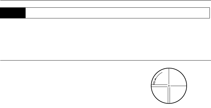
55
11. TARGET SIGHTING
• When sighting the target, strong light shining directly into the objective lens may cause the
instrument to malfunction. Protect the objective lens from direct light by attaching the lens hood.
XPROCEDURE
1. Look through the telescope eyepiece at a bright and
featureless background.
Turn the eyepiece clockwise, then counterclockwise
little by little until just before the reticle image becomes
focussed.
Using these procedures, frequent reticle refocussing is
not necessary, since your eye is focussed at infinity.
2. Use the peep sight to bring the target into the field of
view. Turn the vertical and horizontal jogging knobs for
fine sighting adjustments.
3. Turn the telescope focussing ring to focus on the
target.
Turn the vertical and horizontal fine motion screws to
align the target with the reticle.
The last adjustment of each fine motion screw should
be in the clockwise direction.
4. Readjust the focus until there is no parallax
Readjust the focus with the focussing ring until there is
no parallax between the target image and the reticle.
Eliminating parallax
This is the relative displacement of the target image with respect to the reticle when the
observer's head is moved slightly before the eyepiece.
Parallax will introduce reading errors and must be removed before observations are taken.
Parallax can be removed by refocussing the reticle.
11.3 Manually Sighting the Target
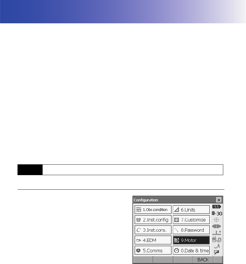
56
12. MEASUREMENT WITH AUTO TRACKING
With the Auto Tracking function, an SRX, sighted on the target using Auto Pointing, will following that
target as it is moved from measurement point to measurmeent point. The On-demand Remote Control
System is recommended for high performance Auto Tracking measurement.
Caution
• The instrument emits a laser beam during Auto Pointing and Auto Tracking operation.
• Auto Pointing can only be performed when a prism is used as the target. Auto Tracking is not
possible with reflective sheet and reflectorless measurement
• Use reflective prisms from Sokkia for higher precision measurement.
• If more than one prism is located in the field of sight during Auto Tracking, an operation error will
occur and the SRX will not be able to find the target.
• The prism beyond the glass can not be searched because measurement error occurs.
• If an obstacle blocks the laser beam path between the SRX and the prism, SRX cannot find the
target correctly.
• Position the prism in alignment with the objective lens. In short distance measurement especially,
make sure to align the prism with the objective lens (within 10 to 15°) to obtain the correct result. A
prism with a prism constant of -40mm can eliminate the error caused by tilted prism.
360 Prism: "11. TARGET SIGHTING Aspect of the 360° Prism"
PROCEDURE
1. Select "Motor" in <Configuration>.
Set Auto Tracking functions in the Configuration
tab.
Set "A.T. Setting" to "Track".
12.1 Auto Tracking Settings
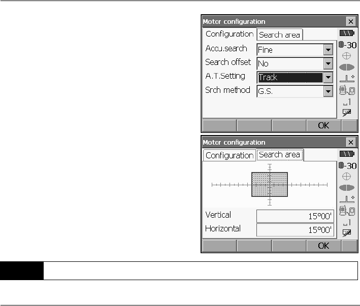
57
12. MEASUREMENT WITH AUTO TRACKING
Configuration tab:"11.1 Auto Pointing Settings"
2. Set the area in which to perform target sighting in
the Search area tab. Drag the box to specify the
desired or area or input vertical and horizontal
angle values.
Angle values can only be specified in 1°30’ steps
(e.g. 15°00’, 16°30’, 18°00’ etc.). Input values not
conforming to this format will be automatically
rounded up.
3. Press [OK].
PROCEDURE
1. Use the peep sight to aim the objective lens in the
general direction of the target. (The vertical and
horizontal jogging knobs can be used for precise
adjustments of the instrument and telescope.)
2. Select [DIST], [RC Cont], or [SRCH] in any Meas
mode screen. The telescope and top half of the
instrument rotate and target auto-search begins.
When the target is found, the instrument sights
the center of the prism and Auto Tracking starts.
Allocating softkeys: "21.6 Allocating Key
Functions"
3. Press [AT Off] in a Meas mode screen to stop
Auto Tracking.
• When [STOP] is pressed, distance measurement
will stop but Auto Tracking will remain active.
12.2 Measurement with Auto Tracking
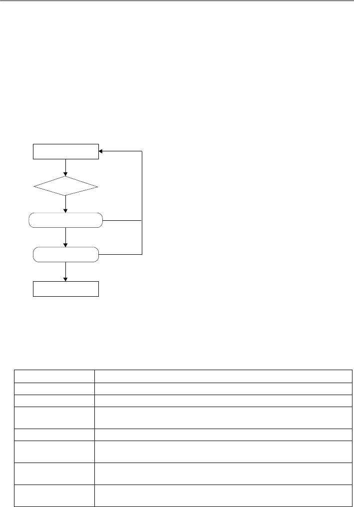
12. MEASUREMENT WITH AUTO TRACKING
58
Lost Prism
In the event that an obstacle prevents the SRX sighting the target during Auto Tracking, the
instrument will predict the direction in which the target will travel and continue Auto Tracking
based on this prediction. If the SRX re-acquires the target in this predicted direction, Auto
Tracking continues without change. If the target is not re-acquired however, Auto Tracking will
stop and the SRX will enter
"prism wait" status for a period of 60 second
s.If the target enters the
field of view or a Turning command is received from the RC Controller during "prism wait", the
SRX will perform Auto Pointing, then resume Auto Tracking. If the target is not re-acquired
during the "prism wait" period, the target is considered "lost" and sighting terminates.
Start Auto Tracking procedure again from step 1.
• The following softkeys can also be used for Auto Pointing when "A.T. Setting" in <Motor
configuration> is set to "Track".
Softkey Function
[DIST] Performs Auto Pointing then Auto Tracking/distance measurement
[SRCH] Performs Auto Pointing then Auto Tracking/distance measurement
[H.ANG] Sets current angle to a specified angle then performs Auto Pointing/
Auto Tracking
[0 SET] Sets current angle to 0 then performs Auto Pointing/Auto Tracking
[RC] Rotates in the direction specified by the On-demand Remote Control
System then performs Auto Pointing/Auto Tracking
[<-RC] Rotates in a counterclockwise direction (from the point of view of the
RC Controller) then performs Auto Pointing/Auto Tracking
[RC->] Rotates in a clockwise direction (from the point of view of the RC
Controller) then performs Auto Pointing/Auto Tracking
"Prism wait"
Target "lost"
Direction predicted
Auto Tracking
Obstacle
Target
Target
Target found
Target found
not found
not found
59
12. MEASUREMENT WITH AUTO TRACKING
[RC Cont] Nullifes the current measurement position, continues Turning
operation, then performs Auto Pointing/Auto Tracking
[AT On] Performs Auto Pointing then Auto Tracking
[ROTATE] Automatically rotates the instrument to the specified vertical and
horizontal angles then performs Auto Pointing/Auto Tracking
[TURN] Rotates the SRX 180
°
then performs Auto Pointing/Auto Tracking
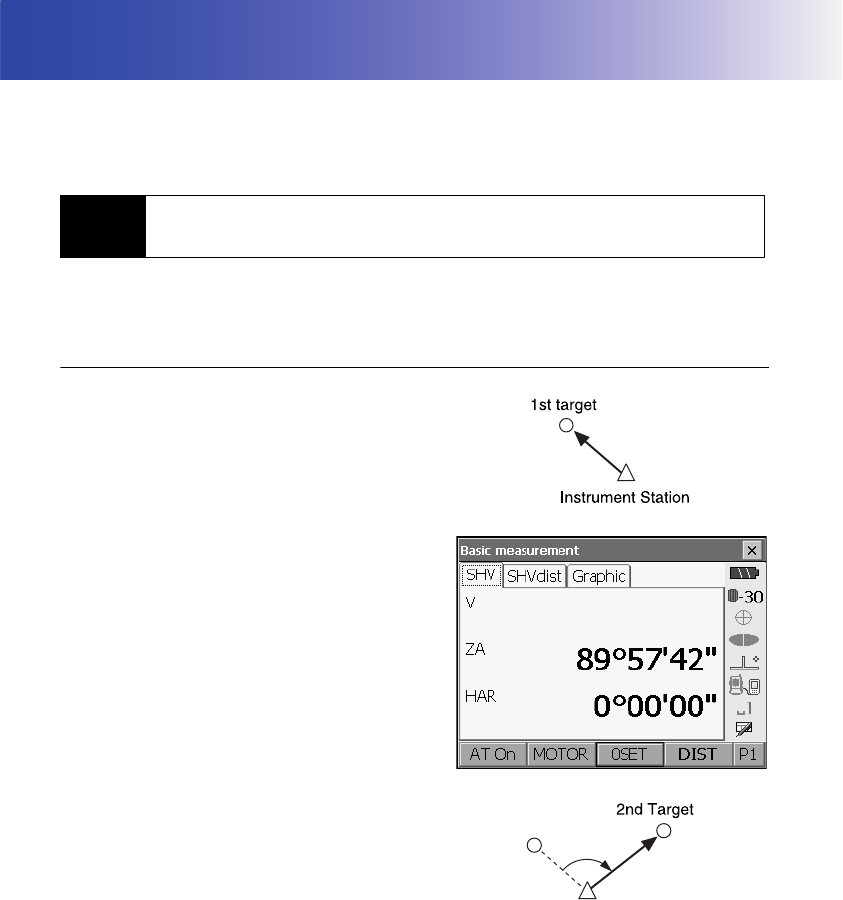
60
13.ANGLE MEASUREMENT
This section explains the procedures for basic angle measurement in Basic mode.
• It is possible to allocate softkeys in measurement menus to suit various applications and the ways
that different operators handle the instrument.
"21.6 Allocating Key Functions"
Use the “0SET” function to measure the included angle between two points. The horizontal angle can
be set to 0 at any direction.
PROCEDURE
1. Sight the first target as at right.
"10.3 TARGET SIGHTING"
2. In the first page of the Meas mode screen, press
[0SET].
[0SET] will flash, so press [0SET] again.
The horizontal angle at the first target becomes 0°.
3. Sight the second target.
13.1 Measuring the Horizontal Angle between Two Points
(Horizontal Angle 0°)
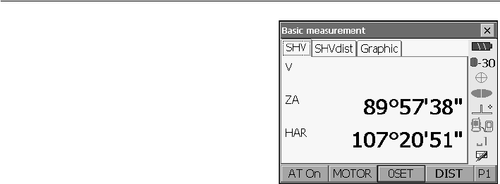
61
13. ANGLE MEASUREMENT
The displayed horizontal angle (HAR) is the
included angle between two points.
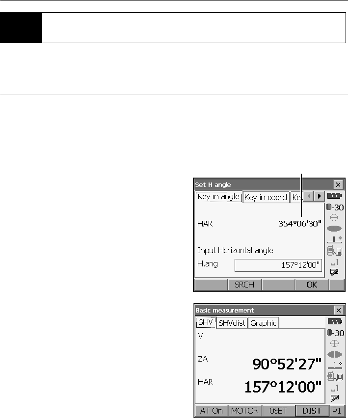
13. ANGLE MEASUREMENT
62
You can reset the horizontal angle to a required value and use this value to find the horizontal angle
of a new target.
PROCEDURE
1. Sight the first target.
2. In the second page of Basic mode, press
[H.ANG]. <Set H angle> is displayed.
3. Enter the angle you wish to set, then press [OK].
The value that is input as the horizontal angle is
displayed.
•Press [SRCH] to rotate the SRX in the direction
of the desired angle.
•The same setting can also be performed with
coordinate and azimuth input.
"15.2 Azimuth Angle Setting"
4. Press [OK] to confirm the input value and display
the new horizontal angle.
5. Sight the second target.
The horizontal angle from the second target to the
value set as the horizontal angle is displayed.
13.2 Setting the Horizontal Angle to a Required Value
(Horizontal Angle Hold)
Current angle

63
13. ANGLE MEASUREMENT
• Pressing [HOLD] performs the same function as above.
•Press [HOLD] to set the displayed horizontal angle. Then, set the angle that is in hold status to the
direction you require.
Allocating [HOLD]: "21.6 Allocating Key Functions"
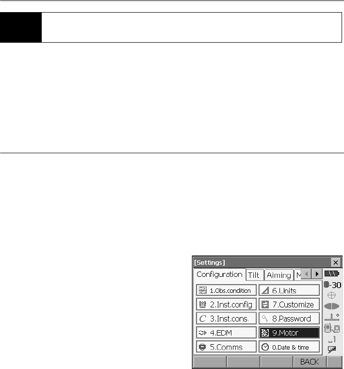
13. ANGLE MEASUREMENT
64
The SRX automatically turns from the reference direction to the specified angle (target).
• SRX also turns to the target coordinates when reference angle is omitted.
• Rotation may not be completed correctly when specifiying an angle near the zenith or nadir if "Tilt
crn." or "Coll. crn" is set to "Yes" in "Obs.condition".
PROCEDURE
1. Sight the point you will use as the reference angle
and set it as the reference angle.
Sight the reference point and press [0SET], or
input the reference point angle.
"13.1 Measuring the Horizontal Angle
between Two Points (Horizontal Angle 0°)"/
"13.2 Setting the Horizontal Angle to a
Required Value (Horizontal Angle Hold)"
2. Press {SETTINGS} to switch to SETTINGS
mode.
13.3 Turning the Instrument from the Reference Angle to a
Specified Angle
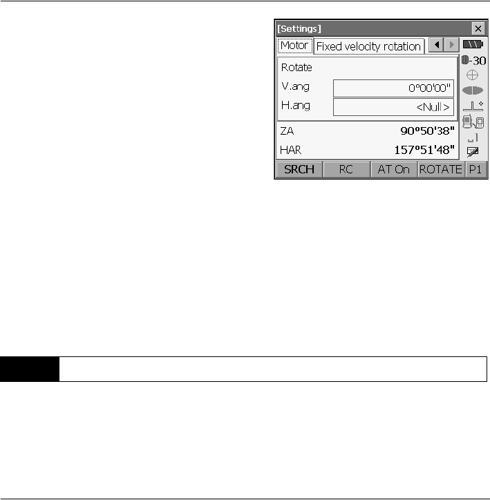
65
13. ANGLE MEASUREMENT
3. Enter the vertical and horizontal angles in the
Motor tab.
• Pressing [READ] in the second page displays
the coordinates data recorded in Program mode
(SDR). This data can be recalled and used for
settings.
Series SRX SDR Software Reference
Manual
• The target angle can be obtained from the
entered instrument station and target
coordinates. Instrument station data is entered
on the second page. Press [OK] to calculate
both the horizontal and vertical angle from the
coordinates.
4. After confirming the coordinates, press
[ROTATE]. The SRX moves to the point (target)
entered in step 3.
The following explains angle measurement and the features used to output measurement results to a
computer or other external devices.
"6.1 CONNECTING TO EXTERNAL DEVICES", Cables: "27. OPTIONAL ACCESSORIES",
Output format and command operations: Interfacing with the SOKKIA SDR Electronic Field Book
and Command Explanations manuals
PROCEDURE
1. Connect SRX and external device.
2. Sight the target point.
3. Press [HV out] in Meas mode to output target
measurement results to the external device.
13.4 Angle measurement and Outputting the Data

66
14.DISTANCE MEASUREMENT
Perform the following settings as preparation for distance measurement in Basic mode.
• Distance measurement mode
• Target type
• Prism constant correction value
• Search area
• Auto Pointing/Auto Tracking
"11.1 Auto Pointing Settings", "12.1 Auto Tracking Settings", "21.3 EDM Settings"
• It is possible to allocate softkeys in measurement menus to suit various applications and the ways
that different operators handle the instrument.
"21.6 Allocating Key Functions"
Caution
• When using the laser-pointer function, be sure to turn OFF the output laser after distance
measurement is completed. Even if distance measurement is canceled, the laser-pointer function is
still operating and the laser beam continues to be emitted. (After turning ON the laser-pointer, the
laser beam is emitted for 5 minutes, and then automatically switches OFF.)
• Make sure that the target setting on the instrument matches the type of target used. SRX
automatically adjusts the intensity of the laser beam and switches the distance measurement
display range to match the type of target used. If the target does not correspond to the target
settings, accurate measurement results cannot be obtained.
• Accurate measurement results cannot be obtained if the objective lens is dirty. Dust it off with the
lens brush first, to remove minute particles. Then, after providing a little condensation by breathing
on the lens, wipe it off with the wiping cloth.
• During reflectorless measurement, if an object with a high reflective factor (metal or white surface)
is positioned between the SRX and the target, accurate measurement results may not be received.
• Scintillation may affect the accuracy of distance of measurement results. Should this occur, repeat
measurement several times and use the averaged value of the obtained results.
Check to make sure that sufficient reflected light is returned by the target sighted by the telescope.
Checking the returned signal is particularly useful when performing long distance measurements.
Caution
• The laser beam is emitted during returned signal checking.
• Manually sight the target when checking the returned signal.
• When the light intensity is sufficient even though the center of the reflective prism and the reticle
are slightly misaligned (short distance etc.), “” will be displayed in some cases, but in fact, accurate
measurement is impossible. Therefore make sure that the target center is sighted correctly.
14.1 Returned Signal Checking
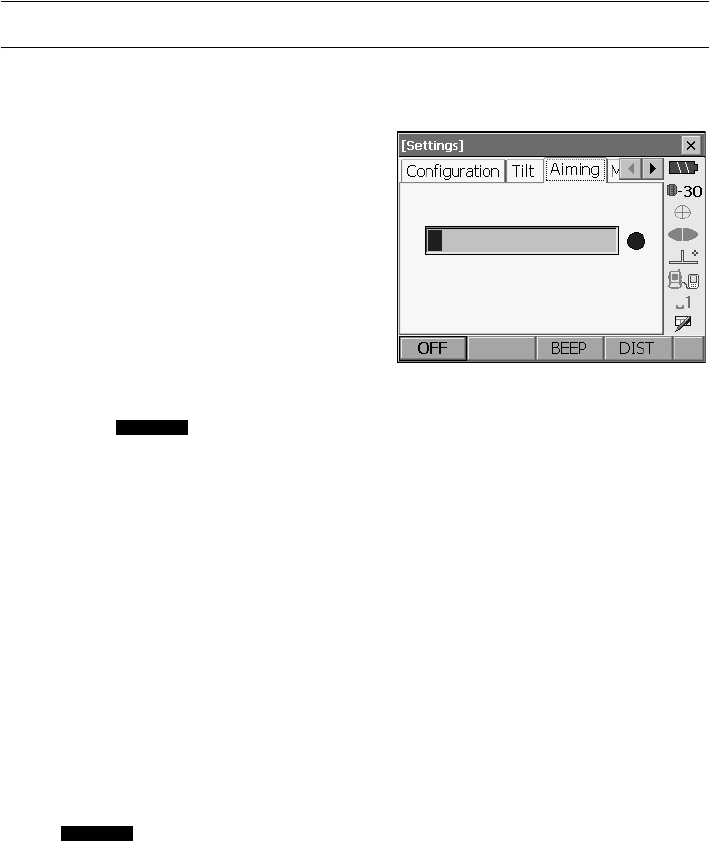
67
14. DISTANCE MEASUREMENT
PROCEDURE
1. Accurately sight the target manually.
"11.3 Manually Sighting the Target"
2. Press {SETTINGS} to switch to SETTINGS mode
and select the Aiming tab or press [AIM] in Meas
mode.
Allocating [AIM]: "21.6 Allocating Key
Functions"
When [AIM] is pressed, a gauge indicating light
intensity is displayed.
• The more displayed, the greater the
quantity of reflected light.
•If “” is displayed, only enough light for the
measurement is returned.
•When “” is not displayed, accurately resight
the target.
[BEEP]/[OFF]: Sets a buzzer sound when
measurement is possible. Press to switch on
and off.
[DIST]: Returns to Meas mode and starts
distance measurement. This softkey is not
displayed when the returned signal checking
function is accessed from Program mode (SDR).
3. Press [OFF] to finish signal checking.
Press
{ESC}
or tap the cross in the top-right
corner to return to the previous screen.
• When is displayed persistently, contact your Sokkia agent.
• If no key operations are performed for two minutes, the display automatically returns to the previous
screen.
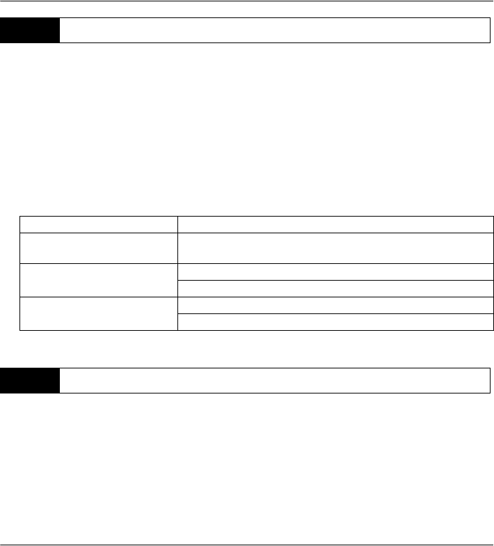
14. DISTANCE MEASUREMENT
68
The color and flashing speed of the guide light indicates the status of the SRX and can be known when
the user is located at a distance from the instrument.
Switching the guide light ON/OFF "5.1 Basic Key Operation"
• The pattern of the guide light can be changed.
"21.2 Instrument Configuration"
• The guide light will turn off, even when set to ON, during distance measurement and returned signal
checking.
An angle can be measured at the same time as distance.
• The search range can be set.
"12.1 Auto Tracking Settings"
Caution
• The laser beam is emitted during Auto Pointing and Auto Tracking.
PROCEDURE
1. Face the SRX in the direction of the target
Use the peep sight to aim the SRX and telescope
toward the target.
"11. TARGET SIGHTING"
14.2 Using the Guide Light
Light status Meaning
Slow flashing (Red and green
simultaneously)
Waiting
Fast flashing (Red and green
simultaneously)
Searching/returned signal checking in progress
Measuring (continuous measurement)
Green and red alternate
flashing
Search error (error screen only)
Distance measurement error (no signal, sighting error)
14.3 Distance and Angle Measurement
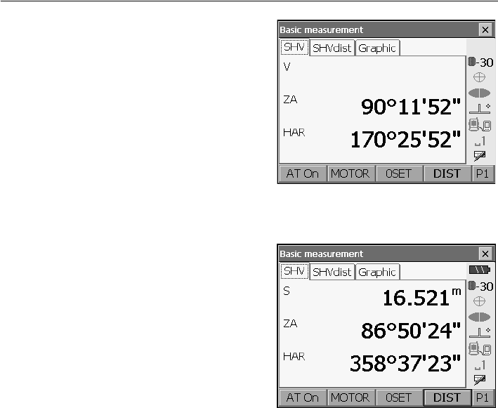
69
14. DISTANCE MEASUREMENT
2. Start measurement.
Press [DIST] in the first page of Meas mode to
start measurement.
The measured distance data (S), vertical angle
(ZA), and horizontal angle (HAR) are displayed.
3. .Press [STOP] to quit distance measurement.
• If the single measurement mode is selected, measurement automatically stops after a single
measurement.
• During fine average measurement, the distance data is displayed as S1, S2,... to S9. When the
designated number of measurements has been completed, the average value of the distance is
displayed in the "SA" line.
• The distance and angle that are most recently measured remain stored in the memory until the
power is off and can be displayed at any time by pressing [RCL].
Allocating [RCL]: "21.6 Allocating Key Functions"
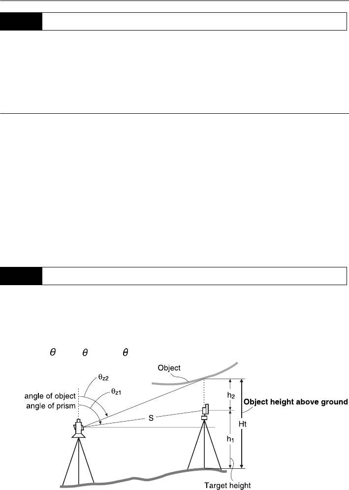
14. DISTANCE MEASUREMENT
70
The following explains distance measurement and the features used to output measurement data to
a computer or external devices.
"8. CONNECTING TO EXTERNAL DEVICES", Communication cables: "27. OPTIONAL
ACCESSORIES". Output format and command operations: Interfacing with the SOKKIA SDR
Electronic Field Book and Command Explanations manuals
PROCEDURE
1. Connect SRX and external device.
2. Sight the target point.
3. Press [HVD out] in Meas mode to start distance
measurement. Target measurement results are
output to the external device.
Output type: "21.6 Allocating Key Functions",
"21.1 Observation Conditions"
4. Press [STOP] to finish data output and return to
the Meas mode.
An REM measurement is a function used to measure the height to a point where a target cannot be
directly installed such as power lines, overhead cables and bridges, etc.
The height of the target is calculated using the following formula.
Ht = h1 + h2
h2 = S sin z1 x cot z2 - S cos z1
• It is possible to allocate softkeys in the REM measurement menu to suit various applications and
the ways that different operators handle the instrument.
14.4 Distance Measurement and Outputting the Data
14.5 REM Measurement
Zenith
Zenith
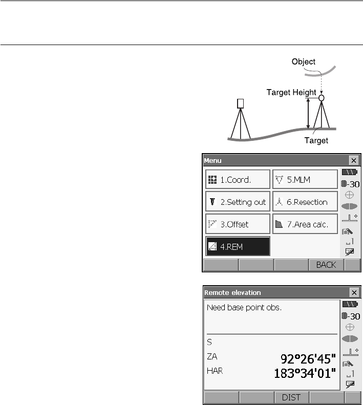
71
14. DISTANCE MEASUREMENT
"21.6 Allocating Key Functions"
PROCEDURE
1. Set the target directly under or directly over the
object and measure the target height with a tape
measure etc.
Press [HT] and enter the target height.
2. Select "REM" in <Menu>.
3. Sight the target and press [DIST] to start
measurement. Press [STOP] to stop the
measurement.
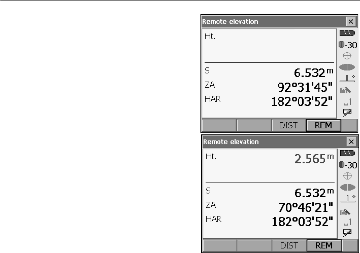
14. DISTANCE MEASUREMENT
72
The measured distance data, vertical angle and
horizontal angle are displayed.
4. Sight the object, then press [REM] to start REM
measurement is started. The height from the
ground to the object is displayed in "Ht.".
Press [STOP] to stop the measurement.
• To re-observe the target, sight the target then
press [DIST].
• To continue REM measurement, press [REM].
• When measurement data already exists, select [REM] in <Menu> as in step 2 to proceed to step
4 and start REM measurement. Press [STOP] to stop the measurement.
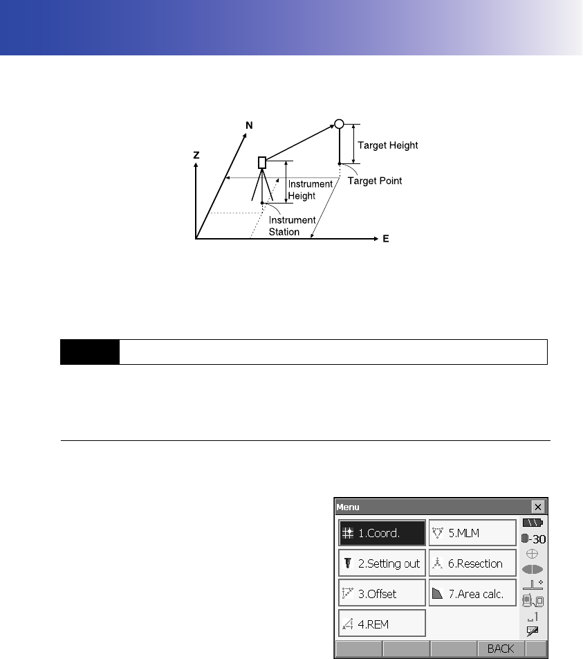
73
15.COORDINATE MEASUREMENT
By performing coordinate measurements it is possible to find the 3-dimensional coordinates of the
target based on station point coordinates, instrument height, target height, and azimuth angles of the
backsight station which are entered in advance.
• It is possible to allocate softkeys in measurement menus to suit various applications and the ways
that different operators handle the instrument.
"21.6 Allocating Key Functions"
Before performing coordinate measurement, enter instrument station coordinates, instrument height
and target height.
PROCEDURE
1. First measure the target height and instrument
height with a tape measure, etc.
2. Select "Coord." in <Menu>.
15.1 Entering Instrument Station Data
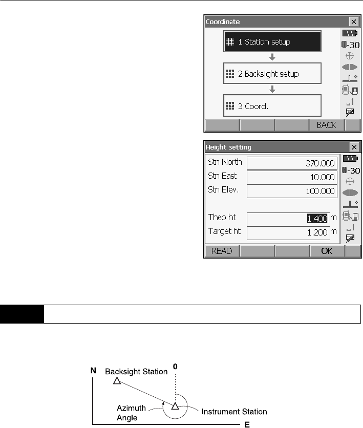
15. COORDINATE MEASUREMENT
74
3. Select "Station setup" and enter instrument
station coordinates, instrument height and target
height.
•Press [READ] to read in coordinate data
registered in Program mode (SDR).
Series SRX SDR Software Reference
Manual
4. Press [OK] to set the input values. <Set H angle>
is displayed again.
Based on the instrument station coordinates and backsight station coordinates which have already
been set, the azimuth angle of the backsight station is calculated.
15.2 Azimuth Angle Setting
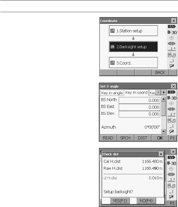
75
15. COORDINATE MEASUREMENT
PROCEDURE Entering coordinates
1. Select "Backsight setup" in <Coordinate>. <Set
H angle> is displayed.
• <Set H angle> can also be displayed from the
screen in step 4 of "15.1 Entering Instrument
Station Data".
2. Select the Key in coord tab and enter the
backsight station coordinates.
•[READ]
:
Reads in coordinate data registered in
Program mode (SDR) .
Series SRX SDR Software Reference
Manual
•
[SRCH]
: R
otates the SRX in the direction of the
desired angle.
• Sight the backsight station and press
[DIST]
.
Press
[STOP]
to display the distance calculated
from coordinates, the measured distance, and
the difference between the two. Press
[YES]
to
set the azimuth angle and display <Coord.
measurement>.
•
[None]
: Switches horizontal angle setting
method.
Horizontal angle settings
3. Press [OK] to set the input values. <Coord.
measurement> is displayed.
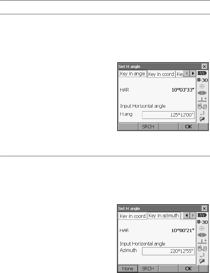
15. COORDINATE MEASUREMENT
76
PROCEDURE Entering angle
1. Select "Backsight setup" in <Coordinate>. <Set
H angle> is displayed.
. <Set H angle> can also be displayed from the
screen in step 4 of "15.1 Entering Instrument
Station Data".
2. Select the Key in angle tab and enter the desired
angle in "H.ang".
•
[SRCH]
: Rotates the SRX in the direction of the
desired angle.
3. Press [OK] to set the input values. <Coord.
measurement> is displayed.
PROCEDURE Entering azimuth
1. Select "Backsight setup" in <Coordinate>. <Set
H angle> is displayed.
. <Set H angle> can also be displayed from the
screen in step 4 of "15.1 Entering Instrument
Station Data".
2. Select the Key in azimuth tab and enter the
desired angle in "H.ang".
•[SRCH]: Rotates the SRX in the direction of the
desired angle.
•
[None]
: Switches horizontal angle setting
method.
"
Horizontal angle settings
"
3. Press [OK] to set the input values. <Coord.
measurement> is displayed.
Horizontal angle settings
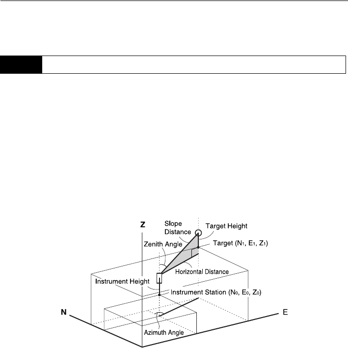
77
15. COORDINATE MEASUREMENT
None (input azimuth angle only)/0 SET (horizontal angle set to 0°)/Azimuth (set both horizontal
and azimuth angles to the same value)/H.ANG (input both horizontal and azimuth angles)
The coordinate values of the target can be found by measuring the target based on the settings of the
instrument station and backsight station.
The coordinate values of the target are calculated using the following formulae.
N1 Coordinate = N0 + S x sinZ x cosAz
E1 Coordinate = E0 + S x sinZ x sinAz
Z1 Coordinate = Z0 + S x cosZ + ih - fh
N0: Station point N coordinate S: Slope distance ih: Instrument height
E0: Station point E coordinate Z: Zenith angle fh: Target height
Z0: Station point Z coordinate Az: Direction angle
"Null" coordinates will not be included in calculations. "Null" is not the same as zero.
15.3 3-D Coordinate Measurement
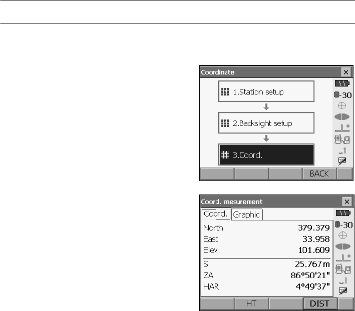
15. COORDINATE MEASUREMENT
78
PROCEDURE
1. Sight the target at the target point.
"
11. TARGET SIGHTING"
2. Select "Coord." in <Coordinate>.
Press
[DIST]
to start measurement.
Press [STOP]
to stop the measurement. The coordinates of the
target point are displayed. Select the Graphic tab
to display coordinates on a graph.
• By pressing [HT], the instrument station data can
be reset. When the target height of the next
target is different, reenter the target height
before beginning the observation.
3. Sight the next target and press [DIST] to begin
measurement. Continue until all targets have
been measured.
4. When coordinate measurement is completed,
press {ESC} or tap the cross in the top-right
corner to return to <Coordinate>
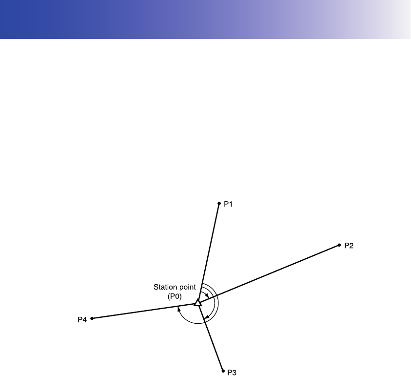
79
16.RESECTION MEASUREMENT
Resection is used to determine the coordinates of an instrument station by performing multiple
measurements of points whose coordinate values are known. Registered coordinate data can be
recalled and set as known point data. Residual of each point can be checked, if necessary
• Between 2 and 10 known points can be measured by distance measurement, and between 3 and
10 known points by angle measurement.
• The more known points there are and the more points there are whose distance can be measured,
the higher the precision of the coordinate value calculation.
• It is possible to allocate softkeys in the Coord. measurement menu to suit various applications and
the ways that different operators handle the instrument.
"21.6 Allocating Key Functions"
Entry Output
Coordinates of
known point : (Ni, Ei, Zi) Station point coordinates : (N0,E0, Z0)
Observed
horizontal angle :Hi
Observed vertical
angle :Vi
Observed distance : Di
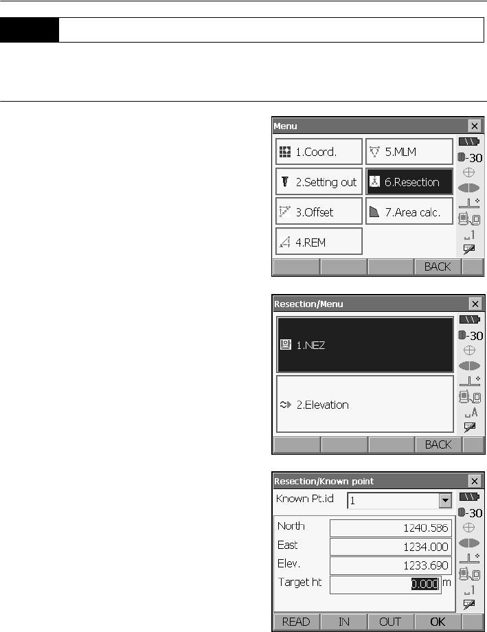
16. RESECTION MEASUREMENT
80
N, E, Z of an instrument station is determined by the measurement.
PROCEDURE
1. Select "Resection" in <Menu>.
2. Select "NEZ" to display <Resection/Known
point>.
3. Input the known point.
After setting the coordinates and target height for
for the first known point press [OUT] to move to
the second point.
• Press [READ] to read in coordinate data
registered in Program mode (SDR).
•Press
[IN] to return to settings for the previous
point.
When all required known points have been set,
press [OK].
16.1 Coordinate Resection Measurement
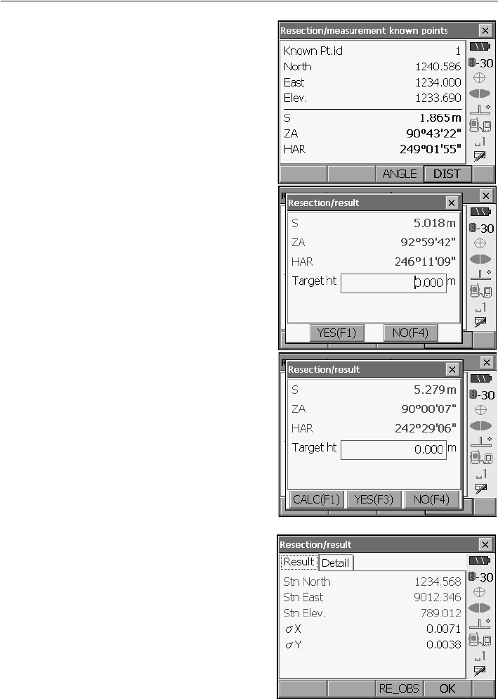
81
16. RESECTION MEASUREMENT
4. Sight the first known point and press [DIST] to
begin measurement.
The measurement results are displayed on the
screen.
• When [ANGLE] has been selected, the distance
cannot be displayed.
5. Press [YES] to use the measurement results of
the first known point.
• You can also input target height here.
•Press [NO] to return to the screen in step 3 and
perform measurement again.
6. Repeat procedures 3 to 4 in the same way from
subsequent points.
When the minimum quantity of observation data
required for the calculation is present, [CALC] is
displayed.
7. Press [CALC] or [YES] to automatically start
calculations after observations of all known points
are completed.
• Instrument station coordinates, station elevation,
and standard deviation, which describes the
measurement accuracy, are displayed.
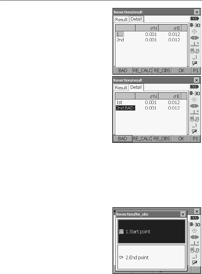
16. RESECTION MEASUREMENT
82
Standard deviation for the northing and easting
coordinates of each point are displayed in the
Detail tab.
8. If there are problems with the results of a point,
align the cursor with that point and press [BAD].
“BAD” is displayed to the right of the point.
Repeat for all results that include problems.
9. Press [RE CALC] to perform calculation again
without the point designated in step 8. The result
is displayed.
If there are no problems with the result, go to step
10.
If problems with the result occur again, perform
the resection measurement from step 3.
•
Press
[RE OBS]
to measure the point
designated in step 8.
If no points are designated in step 8, all the
points or only the final point can be observed
again.
• Press [ADD] when there is a known point that
has not been measured or when a new known
point is added.
10.
Press [OK] in <Resection/result> to display
<Resection/Set h angle>.
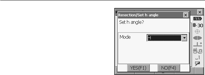
83
16. RESECTION MEASUREMENT
11. Select an angle mode and press
[YES]
to set the
azimuth angle of the first known point as the
backsight point and return to <Resection/Menu>.
12. Press [NO] to return to <Resection/Menu>
without setting the azimuth angle.
Horizontal angle settings
H (set horizontal angle to measured value)/H=Az (set horizontal angle to the same value as
azimuth angle)/Az (set azimuth angle only)
• It is also possible to perform resection measurement by pressing [RESEC] when allocated to the
Meas mode screen.
Allocating
[RESEC]
: "21.6 Allocating Key Functions"
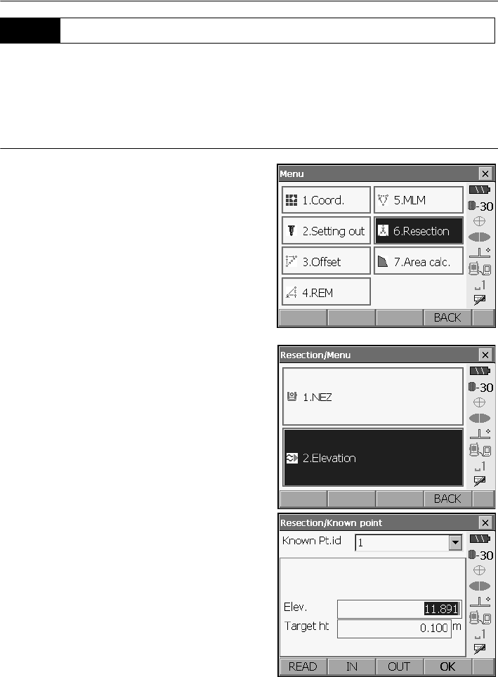
16. RESECTION MEASUREMENT
84
Only Z (height) of an instrument station is determined by the measurement.
• Known points must be measured by distance measurement only.
• Between 1 and 10 known points can be measured.
PROCEDURE
1. Select "Resection" in <Menu>.
2. Select "Elevation" to display <Resection/Known
point>.
3. Input the known point.
After setting the elevation and target height for for
the first known point press [OUT] to move to the
second point.
• Press [READ] to read in data registered in
Program mode (SDR).
•Press
[IN] to return to settings for the previous
point.
When all required known points have been set,
press [OK].
16.2 Height Resection Measurement
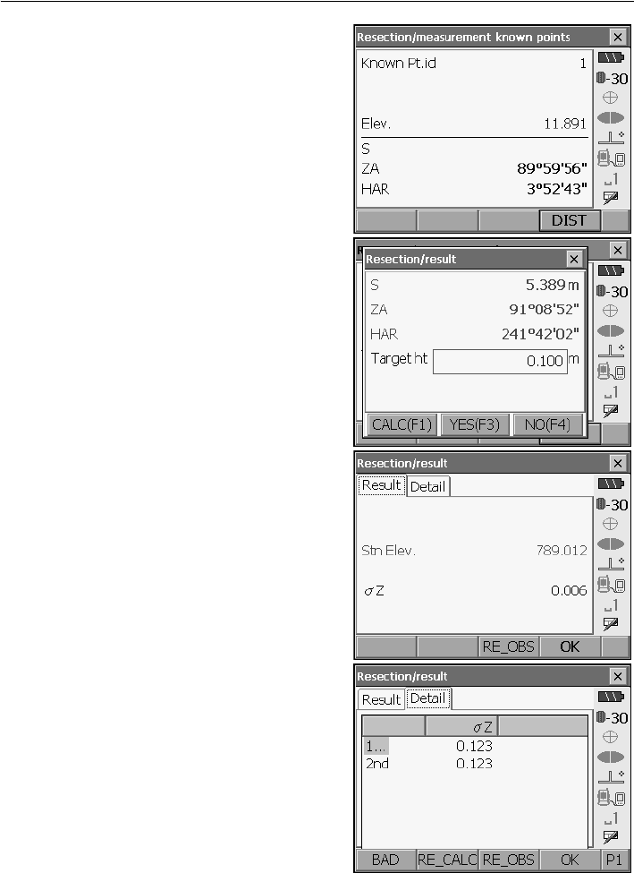
85
16. RESECTION MEASUREMENT
4. Sight the first known point and press [DIST] to
begin measurement.
The measurement results are displayed on the
screen.
• When [ANGLE] has been selected, the distance
cannot be displayed.
5. If measuring two or more known points, repeat
procedures 3 to 4 in the same way from the
second point.
When the minimum quantity of observation data
required for the calculation is present, [CALC] is
displayed
6. Press [CALC] or [YES] to automatically start
calculations after observations of all known points
are completed.
• Instrument station elevation and standard
deviation, which describes the measurement
accuracy, are displayed in the Result tab.
Standard deviation values for each point are
displayed in the Detail tab.
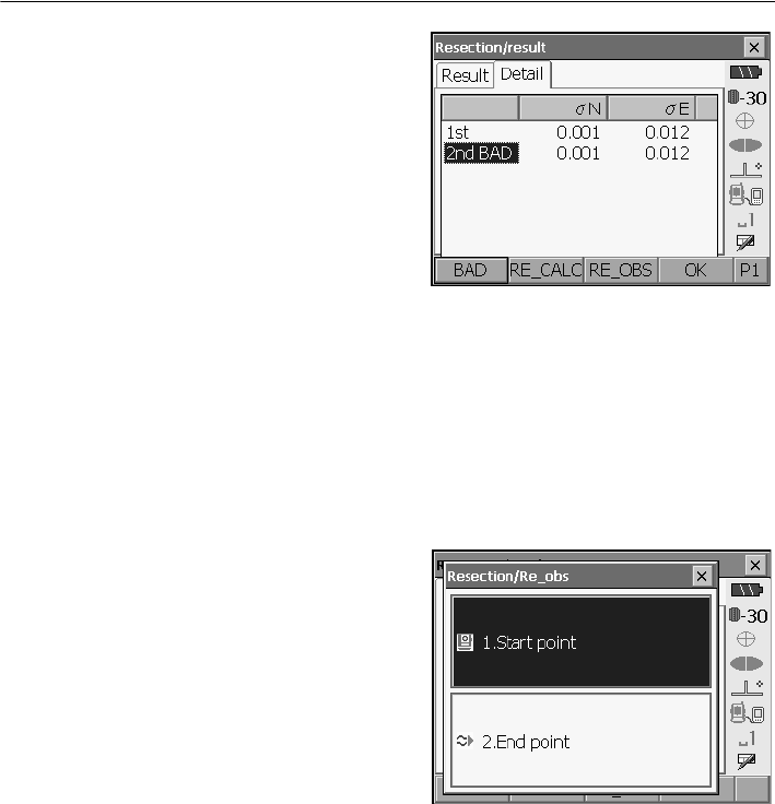
16. RESECTION MEASUREMENT
86
7. If there are problems with the results of a point,
align the cursor with that point and press [BAD].
“BAD” is displayed to the right of the point.
Repeat for all results that include problems.
8. Press [RE CALC] to perform calculation again
without the point designated in step 8. The result
is displayed.
If there are no problems with the result, go to step
10.
If problems with the result occur again, perform
the resection measurement from step 3.
• Press [RE OBS] to measure the point
designated in step 8.
If no points are designated in step 8, all the points
or only the final point can be observed again.
• Press [ADD] when there is a known point that
has not been measured or when a new known
point is added.
9. Press [OK] to finish resection measurement and
return to Meas mode. Only Z (elevation) of the
instrument station coordinate is set. N and E
values are not overwritten.
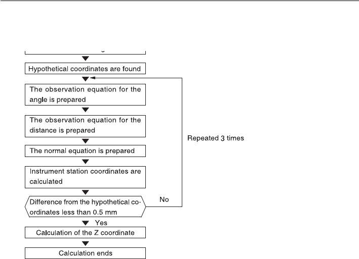
87
16. RESECTION MEASUREMENT
Resection calculation process
The NE coordinates are found using angle and distance observation equations, and the
instrument station coordinates are found using the method of least squares. The Z coordinate
is found by treating the average value as the instrument station coordinates.
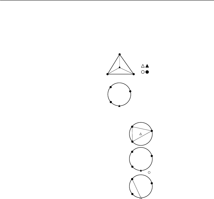
16. RESECTION MEASUREMENT
88
Precaution when performing resection
In some cases it is impossible to calculate the coordinates of an unknown point (instrument
station) if the unknown point and three or more known points are arranged on the edge of a
single circle.
An arrangement such as that shown below is desirable.
It is sometimes impossible to perform a correct calculation in a case such as the one below.
When they are on the edge of a single circle, take one of the following measures.
(1) Move the instrument station as close as possible
to the center of the triangle.
(2) Observe one more known point which is not on the
circle.
(3) Perform a distance measurement on at least one
of the three points.
• In some cases it is impossible to calculate the coordinates of the instrument station if the included
angle between the known points is too small. It is difficult to imagine that the longer the distance
between the instrument station and the known points, the narrower the included angle between the
known points. Be careful because the points can easily be aligned on the edge of a single circle.
: Unknown point
: Known point

89
17.SETTING-OUT MEASUREMENT
Setting-out measurement is used to set out the required point.
The difference between the previously input data to the instrument (the setting-out data) and the
measured value can be displayed by measuring the horizontal angle, distance or coordinates of the
sighted point.
The horizontal angle difference distance difference, and coordinate difference are calculated and
displayed using the following formulae.
Horizontal difference
Displayed value (angle) = Horizontal angle of setting-out data - measured horizontal angle
Displayed value (distance) = measured horizontal distance x tan (horizontal angle of setting out data
- measured horizontal angle)
Slope distance difference
Displayed value (slope distance) * = measured slope distance - slope distance setting-out data
* Horizontal distance or height difference can be input in the above formula.
Coordinate difference
Displayed value (coordinates)* measured N setting-out coordinates - N coordinates of setting-out data
* E or Z coordinates can be input in the above formula
Height difference (REM setting out measurement)
Displayed value (height) = measured REM data - REM data of setting out data
• Setting out data can be input in various modes: slope distance, horizontal distance, height
difference, coordinates and REM measurement.
• It is possible to allocate softkeys in the Setting-out measurement menu to suit various applications
and the ways that different operators handle the instrument.
"21.6 Allocating Key Functions"
When the guide light is set to ON, the flashing speed of the light indicates the status of the SRX and
can be known when the user is located at a distance from the instrument. Also, the flashing colors
relative to the target indicate the direction of the instrument and allow the user to reposition the target.
Turning the Guide light ON/OFF: "5.1 Basic Key Operation"
• The pattern of the guide light can be changed.
"21.2 Instrument Configuration"
• The Guide light will turn off, even when set to ON, during distance measurement and returned signal
checking.
17.1 Using the Guide Light
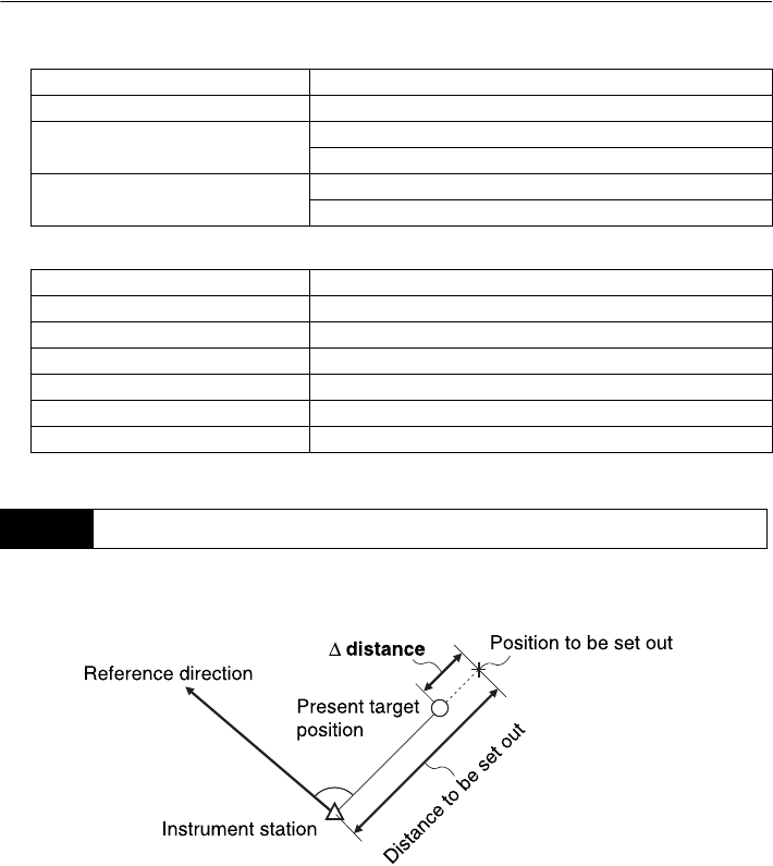
17. SETTING-OUT MEASUREMENT
90
●Guide light status and meaning
Status of SRX
Indication for positioning target during setting-out measurement
The point is to be found based on the horizontal angle from the reference direction and the distance
from the instrument station.
Light status Meaning
Slow flashing Waiting
Fast flashing Searching
Measuring (repeated measurement)
Green and red alternate flashing Search error (error screen only)
Distance measurement error (no signal, sighting error)
Light status Meaning
Increased flashing speed (From position of poleman) Move target away from SRX
Decreased flashing speed (From position of poleman) Move target toward SRX
Fast flashing Target is at correct distance
Red (From position of poleman) Move target left
Green (From position of poleman) Move target right
Red and Green Target is at correct horizontal position
17.2 Distance Setting-out Measurement
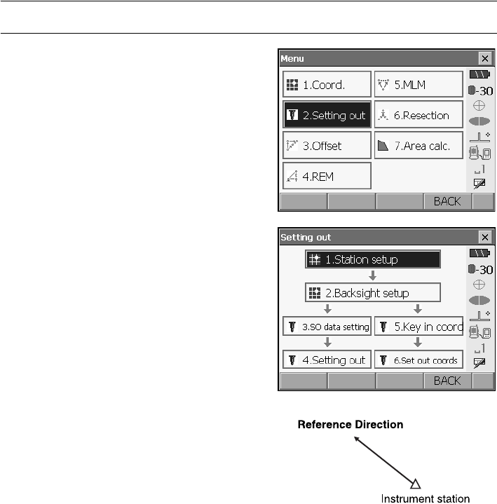
91
17. SETTING-OUT MEASUREMENT
PROCEDURE
1. Select "Setting out" in <Menu> to display <Setting
out>.
2. Select "Station setup" to display <Height setting>.
Enter data for the instrument station and press
[OK] to move to Backsight setup.
"15.1 Entering Instrument Station Data"
•Press [READ] to read in coordinate data
registered in Program mode (SDR).
Series SRX SDR Software Reference
Manual
3. Set the azimuth angle for the backsight station.
Press [OK] to return to <Setting out>.
"15.2 Azimuth Angle Setting"
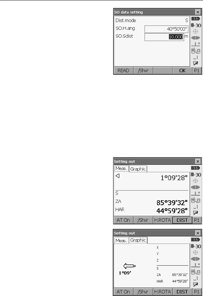
17. SETTING-OUT MEASUREMENT
92
4. Select "SO data setting" In <Setting out> to
display <SO data setting>. Enter the included
angle between the reference point and the
setting-out point in "SO.H.ang", and the distance
(slope distance, horizontal distance or height
difference) from the instrument station to the
position to be set out in "SO.Sdist". Enter the
value in the Distance mode that conforms to your
measurement requirements.
• Each time [/Shvr] is pressed, the distance input
mode changes from "S" (slope distance), "H"
(horizontal distance), "V" (height difference), and
"Ht." (REM).
• When [READ] is pressed, coordinates
registered in Program mode (SDR) can be
recalled and used. The distance selected
according to the selected distance input mode is
calculated using these coordinate values.
Series SRX SDR Software Reference
Manual
• Press [COORD] in the second page and input
coordinates in <Key in coord>. The angle and
distance from these coordinates to the position
to be set out will be calculated.
5. Enter values and press [OK] to display the
screen at right.
Press [H.ROTA] to automatically rotate the SRX
toward the horizontal angle set in step 3 and set
the angle to the setting out point to 0°.
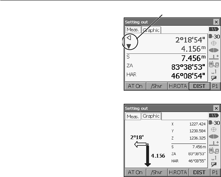
93
17. SETTING-OUT MEASUREMENT
6. Position the target on the line of sight and press
[DIST] to begin distance measurement.
The distance and direction to move the target until
the setting out point is located is displayed on the
SRX. The sighting point measurement results
(currently installed position of the target) are
displayed.
• Movement indicator (Red indicates that target
position is correct)
Arrows indicating horizontal direction will point in
the opposite direction when viewing the display in Face 2.
Y: (Viewed from SRX) Move target to the left
Z : (Viewed from SRX) Move target to the right
YZ : Target position is correct
▼: (Viewed from SRX) Move target closer
▲: (Viewed from SRX) Move target away
▲▼ : (Viewed from SRX) Target position is correct
: Move target upward
: Move target downward
: Target position is correct
• Each time [/Shvr] is pressed, the distance input mode changes from "H" (horizontal distance),
"V" (height difference), "R" (REM), and "S" (slope distance).
•Press [CNFG] to set setting out accuracy. When the position of the target is within this range
both arrows will be displayed to indicate that the target position is correct.
Arrows indicate direction to move
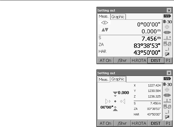
17. SETTING-OUT MEASUREMENT
94
7. Move the target until the distance to the setting-
out point reads 0m. When the target is moved
within the allowed range, all distance and position
arrows are displayed.
8. Press [OK] to return to <Setting out>. Set the
next setting out point to continue setting out
measurement.
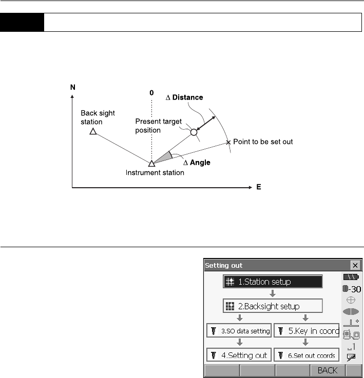
95
17. SETTING-OUT MEASUREMENT
After setting the coordinates for the point to be set out, the SRX calculates the setting-out horizontal
angle and horizontal distance. By selecting the horizontal angle and then the horizontal distance
setting-out functions, the required coordinate location can be set out.
• Previously recorded setting-out points can be placed in order. Up to 30 points can be recorded.
•
T
o find the Z coordinate, attach the target to a pole etc. with the same target height.
PROCEDURE
1. Select "Setting out" in <Menu> to display <Setting
out>.
2. Select "Station setup" to display <Height setting>.
If necessary, enter data for Backsight setup.
"17.2 Distance Setting-out Measurement"
steps 2 to 3
17.3 Coordinates Setting-out Measurement
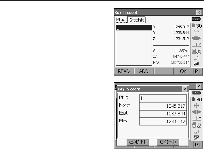
17. SETTING-OUT MEASUREMENT
96
3.
Select "Key in coord" in <Setting out>.
Record all
the setting-out points (includes setting-out points
you will measure from now).
Press [READ] to display recorded angle data or
press [ADD] to record new data.
•Press [DEL] in the second page to delete the
selected setting out point.
• Press [DELALL] in the second page to delete all
setting out points.
4. Select a setting-out point in the first screen of step
3 and press [OK] to display <Set out Coords>.
Press [H.ROTA] to automatically rotate the SRX
until the angle of the setting out point reads 0°.
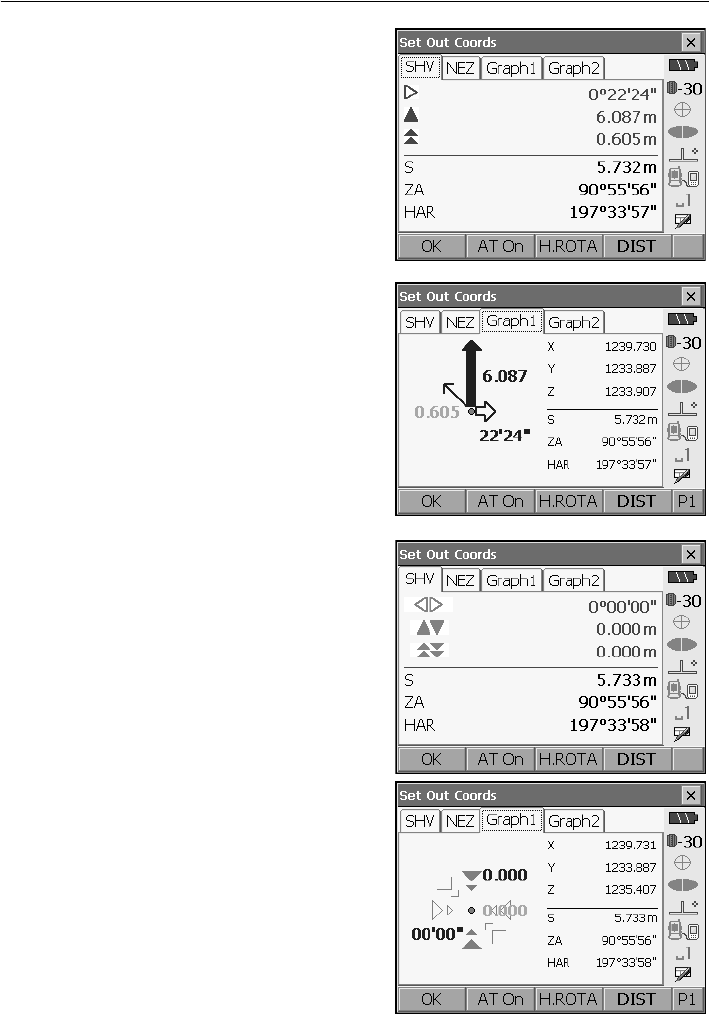
97
17. SETTING-OUT MEASUREMENT
5.
Press
[H.ROTA] to automatically rotate the SRX
until the angle of the setting out point reads 0°.
Position the target on the line of sight and press
[DIST] to begin distance measurement.
The distance and direction to move the target until
the setting out point is located is displayed on the
SRX. The sighting point measurement results
(currently installed position of the target) are
displayed.
• <Set out Coords> can also be displayed by
selecting "Set out coords" in <Setting out>.
• Switch between the tabs to display different sets
of information.
Move the target closer/further away and upward/
downward to find the correct distance (0 is
displayed) to the setting out point.
Movement indicators: "17.2 Distance Setting-
out Measurement" step 5
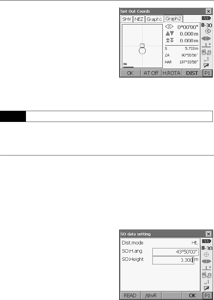
17. SETTING-OUT MEASUREMENT
98
6. Press {ESC} to return to <Key in coord>. Set the
next setting out point to continue setting out
measurement.
To find a point where a target cannot be directly installed, perform REM setting-out measurement.
"14.5 REM Measurement"
PROCEDURE
1. Install a target directly below or directly above the
point to be found. Then use a measuring tape etc.
to measure the target height (height from the
surveying point to the target).
2. Select "Station setup" in <Setting out> to display
<Height setting>. If necessary, enter data for
Backsight setup.
"17.2 Distance Setting-out Measurement"
steps 2 to 3
3. Select "SO data setting" In <Setting out> to
display <SO data setting>. Press [/Shvr] until the
distance input mode is "Ht.". Input height from the
surveying point to the position to be set out in
"SO.Height". If necessary, input the angle to the
point to be set out.
4. Enter values and press [OK] in step 3 to display
the screen at right.
Press [H.ROTA] to automatically rotate the SRX
toward the horizontal angle set in step 3 and set
the angle to the setting out point to 0°.
17.4 REM Setting-out Measurement
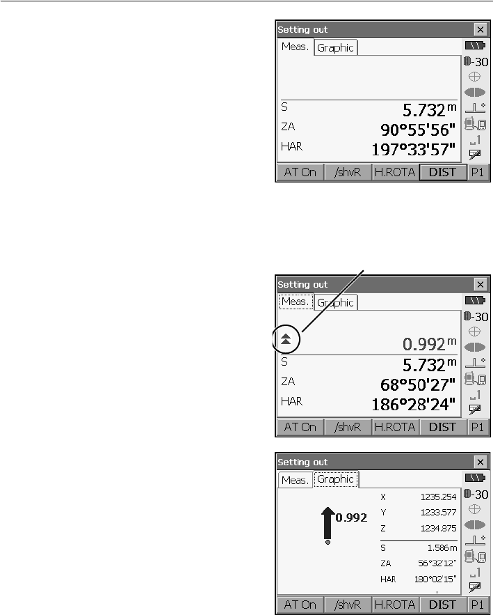
99
17. SETTING-OUT MEASUREMENT
5. Position the target on the line of sight and press
[DIST] to begin distance measurement.
The distance and direction to move the target until
the setting out point is located is displayed on the
SRX. The sighting point measurement results
(currently installed position of the target) are
displayed.
6. Sight the target and press [DIST]. Measurement
begins and the measurement results are
displayed.
7. Press [REM] in the second page to start REM
measurement.
The distance (height difference) and direction to
move the target until the sighting point and setting
out point are located is displayed on the SRX. The
sighting point measurement results are displayed.
Press [STOP] to stop measuring.
Find the setting-out point by moving the telescope
until the distance to the setting-out point reads 0m.
• Movement indicator (Red indicates that target
position is correct)
: : Move the telescope near the zenith
: Move the telescope near the nadir
: Telescope direction is correct
For details of other movement indicators:
"17.2 Distance Setting-out Measurement"
step 5
Arrows indicate direction to move
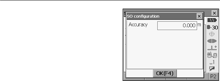
17. SETTING-OUT MEASUREMENT
100
• Press [CNFG] to set setting out accuracy. When
the position of the target is within this range both
arrows will be displayed to indicate that the
target position is correct.
8. Press {ESC} to return to <SO data setting>.
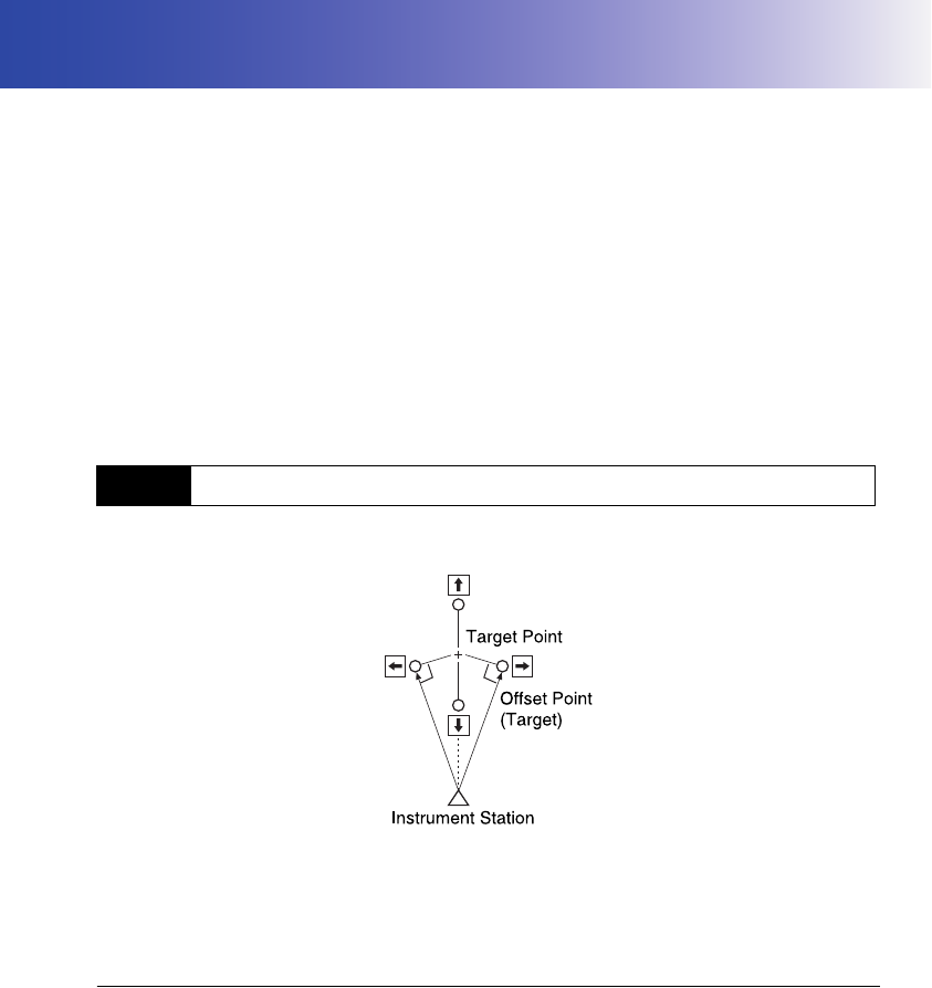
101
18.OFFSET MEASUREMENT
Offset measurements are performed in order to find a point where a target cannot be installed directly
or to find the distance and angle to a point which cannot be sighted.
• It is possible to find the distance and angle to a point you wish to measure (target point) by installing
the target at a location (offset point) a little distance from the target point and measuring the distance
and angle from the surveying point to the offset point.
• The target point can be found in the three ways explained below.
• The instrument station and backsight must be set before the coordinates of an offset point can be
found. Station and backsight setup can be performed in the Offset menu.
Station setup: "15.1 Entering Instrument Station Data", Backsight setup: "15.2 Azimuth Angle
Setting" .
• It is possible to allocate softkeys in the Offset menu to suit various applications and the ways that
different operators handle the instrument
"21.6 Allocating Key Functions"
Finding it by entering the horizontal distance from the target point to the offset point.
• When the offset point is positioned to the left or right of the target point, make sure the angle formed
by lines connecting the offset point to the target point and to the instrument station is almost 90°.
• When the offset point is positioned in front of or behind the target point, install the offset point on a
line linking the instrument station with the target point.
PROCEDURE
1. Set the offset point close to the target point and
measure the distance between them, then set up
a prism on the offset point.
18.1 Single-distance Offset Measurement
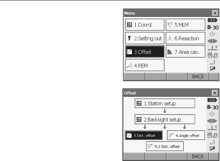
18. OFFSET MEASUREMENT
102
2. Select "Offset" in <Menu> to display <Offset>.
3. Select “Dist. offset”.
Input the following items.
(1) Direction of the offset point.
(2) Horizontal distance from the target point to
the offset point.
• Direction of offset point
4. Sight the offset point and press [DIST] in the
screen of step 3 to start measurement.
Press [STOP] to stop the measurement.
The measurement results are displayed.
•Press [HVD/nez] to switch results for the target
point between distance/angle values and
coordinate/elevation values.
5. Press [OK] in the screen in step 4 to return to
<Offset>.
←: On the left of the target point.
→: On the right of the target point.
↓ : Closer than the target point.
↑: Beyond the target point.
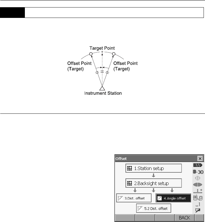
103
18. OFFSET MEASUREMENT
Sighting the direction of the target point to find it from the included angle.
Install offset points for the target point on the right and left sides of and as close as possible to the
target point and measure the distance to the offset points and the horizontal angle of the target point.
PROCEDURE
1. Set the offset points close to the target point
(making sure the distance from the instrument
station to the target point and the height of the
offset points and the target point are the same),
then use the offset points as the target.
2. Select "Offset" in <Menu> to display <Offset>.
Select "Angle offset".
18.2 Angle Offset Measurement
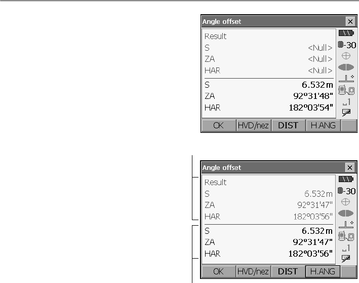
18. OFFSET MEASUREMENT
104
3. Sight the offset point and press [DIST] to start
measurement.
Press [STOP] to stop the measurement.
4. Sight the target point and press [H.ANG].
•Press [HVD/nez] to switch results for the
target point between distance/angle values
and coordinate/elevation values.
5. Press [OK] in the screen in step 4 to return to
<Offset>.
Results for target point
Results for offset point
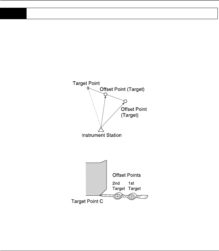
105
18. OFFSET MEASUREMENT
By measuring the distances between the target point and the two offset points.
Install two offset points (1st target and 2nd target) on a straight line from the target point, observe the
1st target and 2nd target, then enter the distance between the 2nd target and the target point to find
the target point.
• It is possible to make this measurement easily using the optional equipment: the 2-point target
(2RT500-K). When using this 2-point target, be sure to set prism constant to 0.
"25. TARGET SYSTEM"
How to use 2-point target (2RT500-K)
• Install the 2-point target with its tip at the target point.
• Face the targets toward the instrument.
• Measure the distance from the target point to the 2nd target.
• Set the prism constant to 0mm.
PROCEDURE
1. Install two offset points (1st target, 2nd target) on
a straight line from the target point and use the
offset points as the target.
18.3 Two-distance Offset Measurement
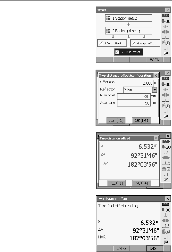
18. OFFSET MEASUREMENT
106
2. Select "Offset" in <Menu> to display <Offset>.
Select "2 Dist. offset".
3. Press [CNFG] and input the distance from the
2nd target to the target point in "Offset dist.".
Select and reflector type and press [OK] to finish
settings.
•Press [LIST] to edit the prism constant and
aperture in <Reflector setting>.
4. Sight the 1st target and press [DIST] to start
measurement.
Press
[STOP]
to stop the measurement. The
measurement results are displayed. Press [YES]
to confirm.
5. Sight the 2nd target and press [DIST] to start
measurement.
Press [STOP] to stop the measurement. The
measurement results are displayed.
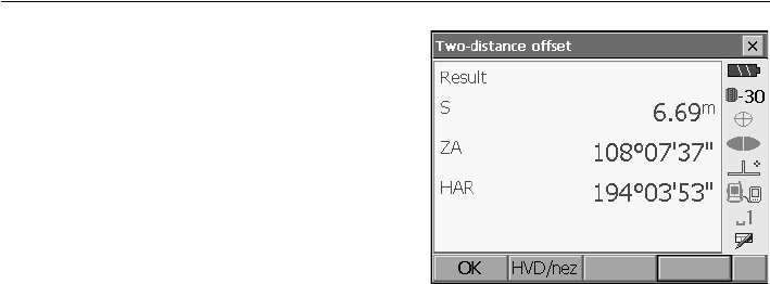
107
18. OFFSET MEASUREMENT
6. Press [YES] to display results for the target point.
Press [HVD/nez] to switch results for the target
point between distance/angle values and
coordinate/elevation values.
7. Press [YES] in the screen in step 4 to return to
<Offset>
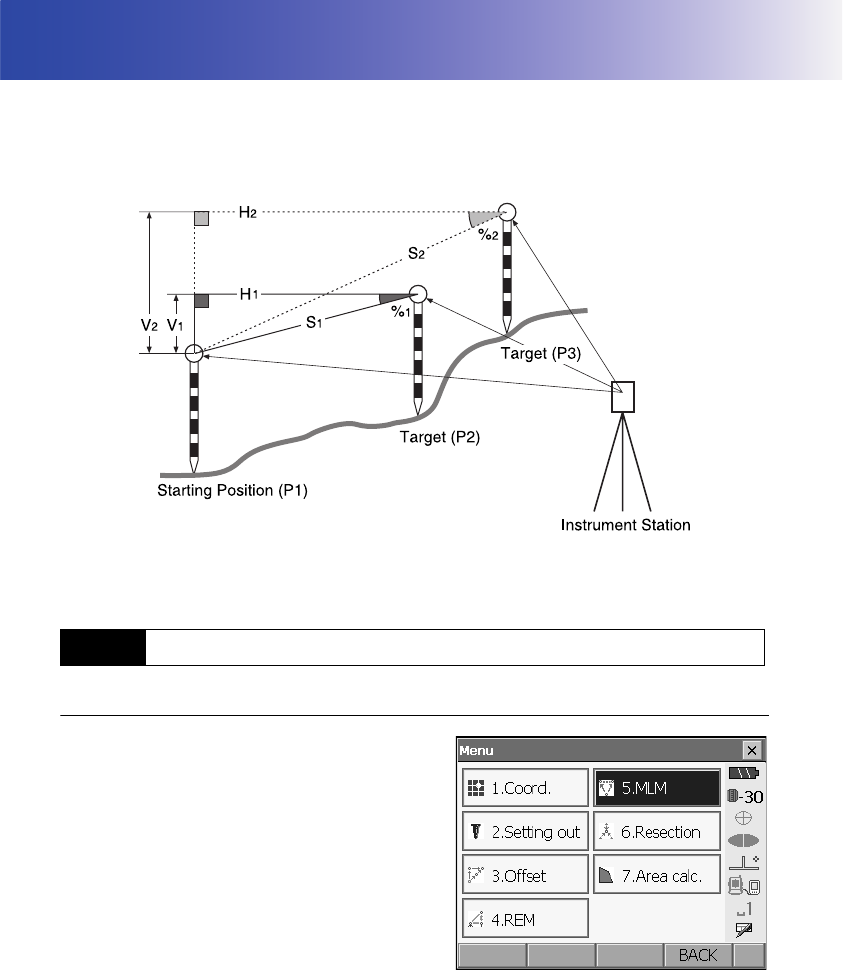
108
19.MISSING LINE MEASUREMENT
Missing line measurement is used to measure the slope distance, horizontal distance, and horizontal
angle to a target from the target which is the reference (starting point) without moving the instrument.
• It is possible to change the last measured point to the next starting position.
• Measurement results can be displayed as the gradient between two points.
• It is possible to allocate softkeys in the MLM menu to suit various applications and the ways that
different operators handle the instrument.
"21.6 Allocating Key Functions"
PROCEDURE
1. Select "MLM" in <Menu>.
19.1 Measuring the Distance between 2 or more Points
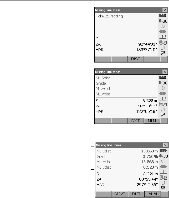
109
19. MISSING LINE MEASUREMENT
2. Sight the second target, and press [DIST] to start
measurement.
Press [STOP] to stop measurement.
The following values are displayed:
S : Slope distance of the starting position and
2nd target.
H : Horizontal distance of the starting position
and 2nd position.
V : Height difference of the starting position and
2nd target.
• When measurement data already exists the
screen of step 3 is displayed and measurement
starts.
3. Sight the next target and press [MLM] to
begin observation. Slope distance, horizontal
distance and height difference between
multiple points and the starting position can
be measured this way.
•Press [DIST] to re-observe the starting
position. Sight the starting position and
press [DIST].
• When [MOVE] is pressed, the last target
measured becomes the new starting
position to perform missing line
measurement of the next target.
4. "19.2 Changing the Starting Point"
5. Press {ESC} or tap the cross in the top-right
corner to end missing line measurement.
Results for current point
Results for measurement between starting
position and second target
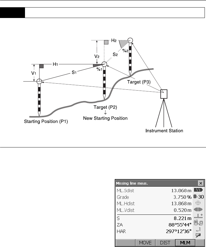
19. MISSING LINE MEASUREMENT
110
It is possible to change the last measured point to the next starting position.
PROCEDURE
1. Observe the starting position and target following
steps 1 to 3 in "19.1 Measuring the Distance
between 2 or more Points".
2. After measuring the targets, press [MOVE].
19.2 Changing the Starting Point
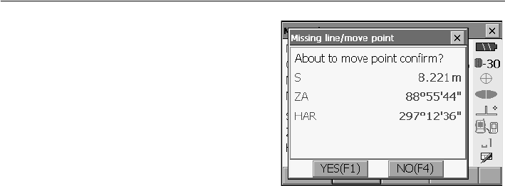
111
19. MISSING LINE MEASUREMENT
Press [YES] in the confirmation message window.
•Press [NO] to cancel measurement.
3. The last target measured is changed to the new
starting position.
4. Perform missing line measurement following
steps 2 to 3 in "19.1 Measuring the Distance
between 2 or more Points".
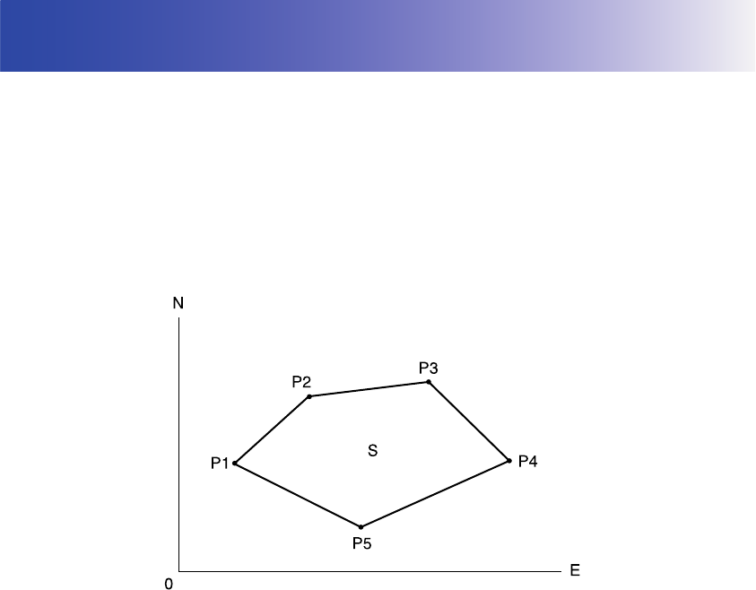
112
20.SURFACE AREA CALCULATION
You can calculate the area of land (slope area and horizontal area) enclosed by three or more known
points on a line by inputting the coordinates of the points
• Number of specified coordinate points: 3 or more, 30 or less
• Surface area is calculated by observing in order the points on a line enclosing an area or by reading
in the previously registered coordinates and using it as known point data.
• It is possible to allocate softkeys in the MLM menu to suit various applications and the ways that
different operators handle the instrument.
"21. CHANGING THE SETTINGS"
• An error will occur if only two points (or less) are entered (or recalled) when specifying an enclosed
area.
• Be sure to observe (or recall) points on an enclosed area in a clockwise or counterclockwise
direction. For example, the area specified by entering (or recalling) point numbers 1, 2, 3, 4, 5 or 5,
4, 3, 2, 1 implies the same shape. However, if points are not entered in numerical order, the surface
area will not be calculated correctly.
Slope area
The first three points specified (measured/read-in) are used to create the surface of the slope
area. Subsequent points are projected vertically onto this surface and the slope area calculated.
Input Output
Coordinates:P1 (N1, E1, Z1) Surface area:S (horizontal area and slope
area)
P2 (N2, E2, Z2)
P3 (N3, E3, Z3)
:
:
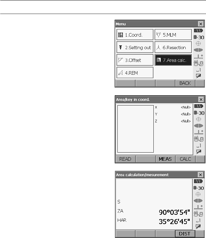
113
20. SURFACE AREA CALCULATION
PROCEDURE Surface area calculation by measuring points
1. Select "Area calc." in <Menu>.
• When [READ] is pressed, registered
coordinates can be recalled and used in
subsequent measurements.
"PROCEDURE Surface area calculation
using registered coordinate data"
2.
Press
[MEAS]
to display <Area calculation/
measurement>.
Sight the first point on the line
enclosing the area, and press [DIST].
Measurement begins and the measured values
are displayed. Press [STOP] to stop measuring.
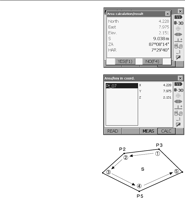
20. SURFACE AREA CALCULATION
114
3. The measurement results are displayed. Press
[YES] to confirm.The value of point 1 is set in
"01".
4. Repeat steps 3 to 4 until all points have been
measured. Points on an enclosed area are
observed in a clockwise or counterclockwise
direction.
For example, the area specified by entering point
numbers 1, 2, 3, 4, 5 or 5, 4, 3, 2, 1 implies the
same shape.
After all known points necessary to calculate the
surface area have been observed, [CALC] is
displayed.
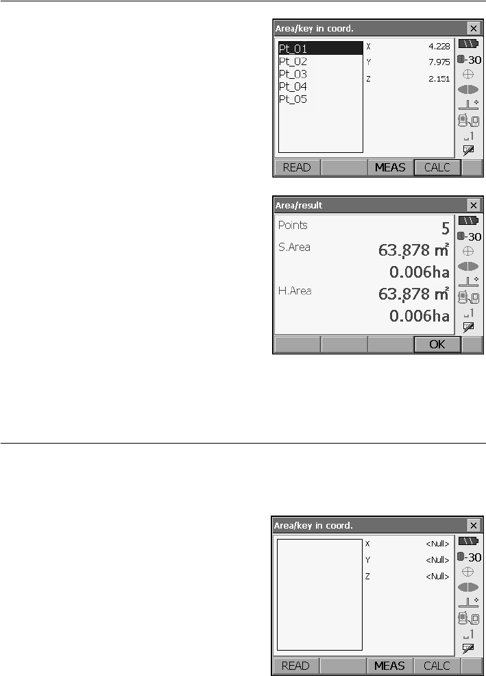
115
20. SURFACE AREA CALCULATION
5. Press [CALC] to display the calculated area.
6. Press [OK] to return to <Area/key in coord.>.
Press {ESC} or tap the cross in the top-right
corner to quit area calculation.
PROCEDURE Surface area calculation using registered coordinate data
Coordinate data registered in Program mode (SDR) can be recalled and used for area calculations.
Series SRX SDR Software Reference Manual
1. Select "Area calc." in <Menu>.
2. Press [READ] to display the list of registered
coordinate data.
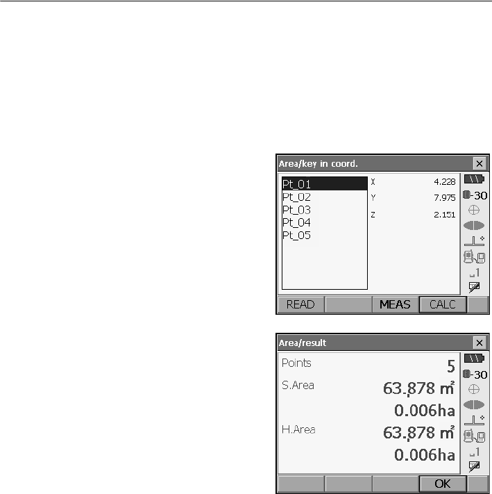
20. SURFACE AREA CALCULATION
116
3. Select the first point in the list and press [OK].
The coordinates of the first point are set as "01".
4. Read in coordinates of point 2 and onward
Repeat steps 2 to 3 until all points have been read
in.
Points on an enclosed area are read in a clockwise
or counterclockwise direction.
After all known points necessary to calculate the
surface area have been observed, [CALC] is
displayed.
5. Press [CALC] to display the calculated area.
6. Press [OK] to return to <Area/key in coord.>.
Press {ESC} or tap the cross in the top-right
corner to quit area calculation.
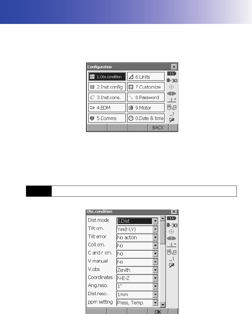
117
21.CHANGING THE SETTINGS
This section explains the contents of parameter settings in Basic mode and how to change these
settings.
Each item can be changed to meet your measurement requirements.
SETTINGS mode can be accessed either by pressing {SETTINGS} or the "SETTINGS" icon in <Top>.
The following chapters provide details of items in SETTINGS mode.
• Communication settings "8. CONNECTING TO EXTERNAL DEVICES"
• Motor settings "11.1 Auto Pointing Settings", "12.1 Auto Tracking Settings"
• Instrument configurations "23.3 Tilt Sensor", "23.5 Reticle".
21.1 Observation Conditions
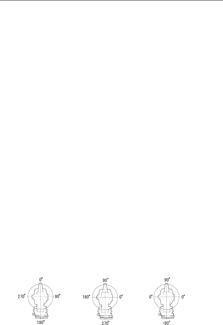
21. CHANGING THE SETTINGS
118
Items set and options (*: Factory setting)
Distance mode: S.Dist (slope distance)*, H.dist (horizontal distance), V.dist
(height difference)
Tilt crn (tilt correction): Yes (H,V)*, Yes (V), No
Tilt error: No action*/Go to Tilt screen
Coll.crn. (collimation correction): No*, Yes
C and r crn.: No*, K=0.142, K=0.20
V manual: Yes, No*
V.obs (vertical angle display method): Zenith*, Horiz., Horiz ±90°
Coordinates: N-E-Z*, E-N-Z
Ang.reso. (Angle resolution): SRX1/SRX2: 0.5"1"*
SRX3/SRX5: 1"*, 5"
Dist.reso. (Distance resolution): SRX1/SRX2: 0.1mm, 1mm*
SRX3/SRX5: 1mm*
ppm setting: Press, Temp.*, +Humidity
• When "V manual" is set to "No" the horizontal angle will be automatically set to 0.
Setting V manual to "Yes": "30.1 Manually Indexing the Vertical Circle by Face Left, Face
Right Measurement"
Automatic tilt angle compensation mechanism
The vertical and horizontal angles are automatically compensated for small tilt errors using the
2-axis tilt sensor.
• Read the automatically compensated angles when the display has stabilized.
• The horizontal angle error (vertical axis error) fluctuates according to the vertical axis, so when the
instrument is not completely leveled, changing the vertical angle by rotating the telescope will cause
the displayed horizontal angle value to change.
• Compensated horizontal angle = Measured horizontal angle + Tilt in angle / tan (Vertical angle)
• When the telescope is directed close to the zenith or nadir angle, tilt compensation is not applied to
the horizontal angle.
Collimation correction
The SRX has a collimation correction function that automatically corrects horizontal angle errors
caused by horizontal axis and leveling axis errors.
V mode (vertical angle display method)
Zenith Horiz Horiz 90°
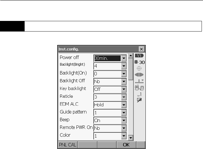
119
21. CHANGING THE SETTINGS
Items set and options (*: Factory setting)
Power off: 5min./10min./15min./30min.*/No
Backlight (Reticle ON): 0 to 8 (6*) (Brightness level on pressing {})
Backlight (Normal): 0 to 8 (2*)
Backlight Off: 30sec/1min./5min./10min./No*
Key backlight: Off*/On
Reticle: 0 to 5 level (3*)
EDM ALC: Hold*, Free
Guide pattern: 1* (simultaneous), 2 (alternating)
Beep: Off/On*
Remote PWR-On: Yes/No*/Yes(Serial)/Yes(Bluetooth)
Color: 1*/2 (monochrome)
Backlight settings
Pressing {} switches the brightness level of the backlight between the settings made in
"Backlight (Reticle ON)" and "Backlight (Normal)".
When "Backlight (Reticle ON)" is selected the reticle will also be illuminated.
When the SRX is powered ON the brightness level is set to "Backlight (Normal)". "Backlight
(Normal)" was set to a higher brightness level than "Backlight (Reticle ON)" when the SRX was
shipped but these values can be modified according to user preferences.
21.2 Instrument Configuration
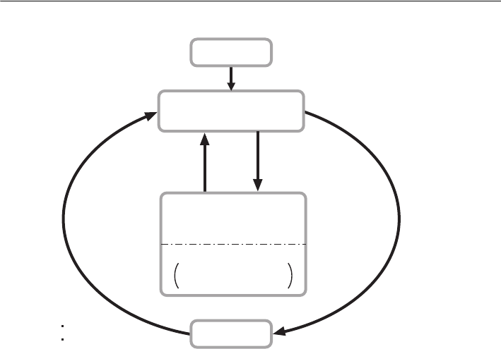
21. CHANGING THE SETTINGS
120
•Press [PNL CAL] to display the touch panel calibration screen.
"10.1 Configuring the Touch Panel"
Power-saving automatic cut-off/Backlight Off
To save power, power to the SRX is automatically cut off if it is not operated for the selected time.
The backlight will similarly be turned off if the instrument is not operated for the selected time.
However, the backlight will not be turned off when "Backlight" is set to "ON".
EDM ALC
Set the light receiving status of the EDM. While carrying out continuous measurement, set this
item according to the measurement conditions.
• When EDM ALC is set to "Free," the instrument’s ALC will be automatically adjusted if an error
occurs as a result of the amount of light received. Set to "Free" when the target is moved during
measurement or different targets are used.
• When "Hold" is set, the amount of light received will not be adjusted until continuous
measurement is completed.
• If an obstacle intermittently obstructs the light beam during continuous measurement and the
"Signal off" error occurs, each time the obstruction occurs it takes some time for the amount of
light received to be adjusted and the measurement value displayed. Set to "Hold" when the light
beam used for measurement is stable but is frequently obstructed by obstacles such as people,
cars, or tree branches etc.
OFF
Backlight (Normal)
brightness
{J}
Reticle backlight ON
{J}
Reticle backlight OFF
Time set in
"Backlight Off" elapses
Key pressed
Touch panel operated
Backlight
(Reticle ON)
brightness
Only when "Key
backlight" set to "ON"
Key backlight ON
Power ON
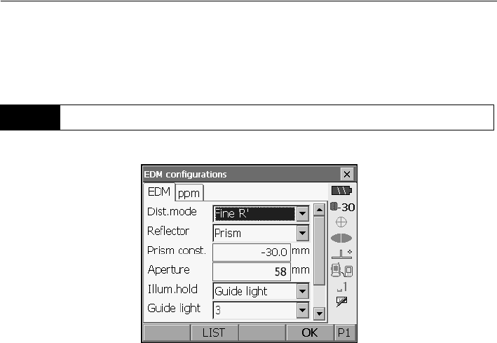
121
21. CHANGING THE SETTINGS
• The EDM ALC setting will automatically be switched to "Free" when the distance measurement
mode is set to "Tracking" (target is moved during distance measurement).
• EDM tab
Items set, options, and input range (*: Factory setting)
Dist. mode (Distance measurement mode): Fine “R”*, Fine AVG n= 2 (Setting: 2 to 9 times), Fine
“S”, Rapid “S”, Rapid "R", Tracking
Reflector: Prism*/360° Prism/Sheet/Reflectorless
Prism constant: -99 to 99 mm ("Prism" is selected: -30*, "360° Prism" is
selected: -7, "Sheet" is selected: 0)
Aperture: 1 to 999mm ("Prism" is selected: -58*, "360° Prism" is
selected: 34, "Sheet" is selected: 20)
Illum. hold ({} function): Guide light*/Laser-pointer
Guide light (Bright): 1 to 3 (3*)
• The setting for "Fine AVG" distance measurement mode can be increased/decreased using the
[ + ]/[ - ] softkeys.
• Target information can be edited and recorded.
"PROCEDURE Recording and editing target information"
• "Prism constant" and "Aperture" will not be displayed when Reflectorless" is selected in
"Reflector".
• The Guide light brightness item ("Guide light (Bright)") will be displayed only when "Illum. hold"
is set to "Guide light".
Prism constant correction
Reflective prisms each have their prism constant.
Set the prism constant correction value of the reflective prism you are using. When selecting
"Reflectorless" in "Reflector", prism constant correction value is set to "0" automatically.
21.3 EDM Settings
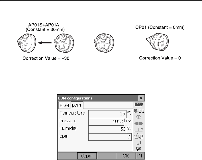
21. CHANGING THE SETTINGS
122
・The following are samples of the prism constant correction values of reflective prisms from
Sokkia.
Prism constants and aperture settings can be set for each prism. The prism constant and
aperture values displayed in the EDM tab will change to reflect the reflector type selected in
"Reflector".
●ppm tab
•[0ppm]: Atmospheric correction factor returns to 0 and temperature and air pressure are set to
the factory settings.
• Atmospheric correction factor is calculated and set using the entered values of the temperature
and air pressure. Atmospheric correction factor can also be entered directly.
Items set, options, and input range (*: Factory setting)
Temperature: -30 to 60°C (15*)
Pressure: 500 to 1400hPa (1013*), 375 to 1050mmHg (760*)
Humidity: 0 to 100% (50*)
ppm (Atmospheric correction factor): -499 to 499 (0*)
•The "Humidity" item is displayed only when the "ppm setting" in "Obs. condition" is set to
"+Humidity".
Atmospheric correction factor
The SRX measures the distance with a beam of light, but the velocity of this light varies
according to the index of refraction of light in the atmosphere. This index of refraction varies
according to the temperature and air pressure.
• To precisely determine the atmospheric correction factor, the average temperature and air
pressure along the measurement beam route must be taken. Take care when calculating the
correction factor in mountainous terrain as the difference in height will result in differences in
atmospheric conditions between two points.
• The SRX is designed so that the correction factor is 0 ppm at an air pressure of 1013 hPa and
a temperature of 15°C.
AP01AR (Constant = 40mm)
Correction Value = -40
R
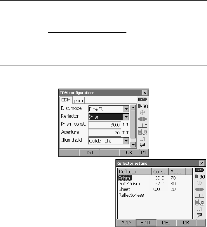
123
21. CHANGING THE SETTINGS
• By inputting the temperature and air pressure values, the atmospheric correction value is
calculated and set into the memory. Calculate the atmospheric correction factor as shown in the
following formula.
"30.2 Atmospheric Correction for High Precision Distance Measurement"
•If the weather correction is not required, set the ppm value to 0.
PROCEDURE Recording and editing target information
The [LIST] softkey is be displayed when either "Reflector" or "Prism const." is selected in the EDM tab
of <EDM configurations>.
1. Press [LIST] to display a list of all recorded
targets.
•[ADD]: Displays <Reflector list>. Select the
desired target from this list and press [OK] to
add to the list in <Reflector setting>. Up to a
maximum of 6 targets can be recorded.
•[DEL]: Deletes the selected target.
ppm = 282.59 - 0.2942 x air pressure (hPa)
1 + 0.003661 x air temperature (°C)
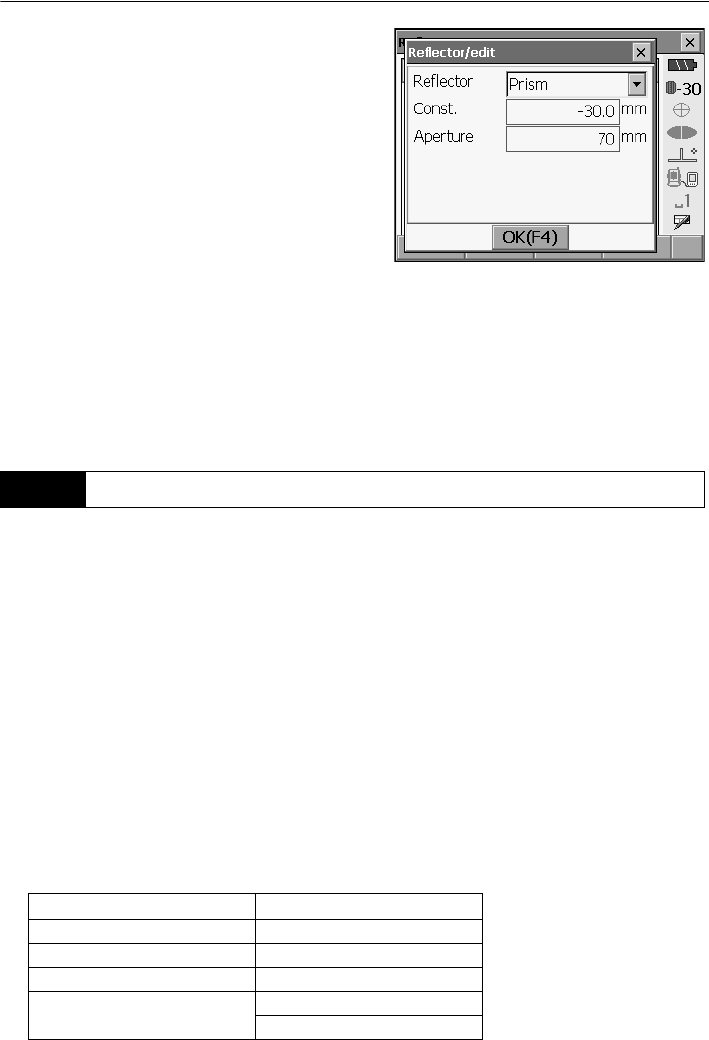
21. CHANGING THE SETTINGS
124
2. To edit a target, select the desired target and
press [EDIT]. <Reflector/edit> is displayed.
Select/input relevant information for the target.
Target: Prism/mini-Prism/Sheet/
Reflectorless/360° Prism
Const.: -99 to 99 mm
Aperture: 1 to 999 mm
• When selecting "Reflectorless" in "Reflector",
prism constant correction and aperture values
are set to "0" automatically.
3. Press [OK] in the screen of step 2 to save edited
information and return to <Reflector setting>.
Press [OK] to return to <EDM configurations>.
It is possible to allocate tabs in Meas mode to suit the measurement conditions. It is possible to
operate the SRX efficiently because unique tab allocations can be preset to suit various applications
and the ways that different operators handle the instrument.
• The current tab allocations are retained until they are revised again, even when the power is cut off.
•Press [CLEAR] in <Customize/Select screen> to return all customized configurations to their
previous settings.
• One screen can contain a maximum of 5 tabs.
• When tab allocations are recorded and registered, the previously recorded tab settings are cleared.
Åú Tab allocations
The following are tabs allocated when the SRX was shipped and tabs that can be defined by the
user.
• Basic measurement
21.4 Allocating User-defined Tabs
Factory settings User-definable tabs
SHV SHV
SHVdist SHVdist
Graphic Graphic
SHV + Coord.
Free
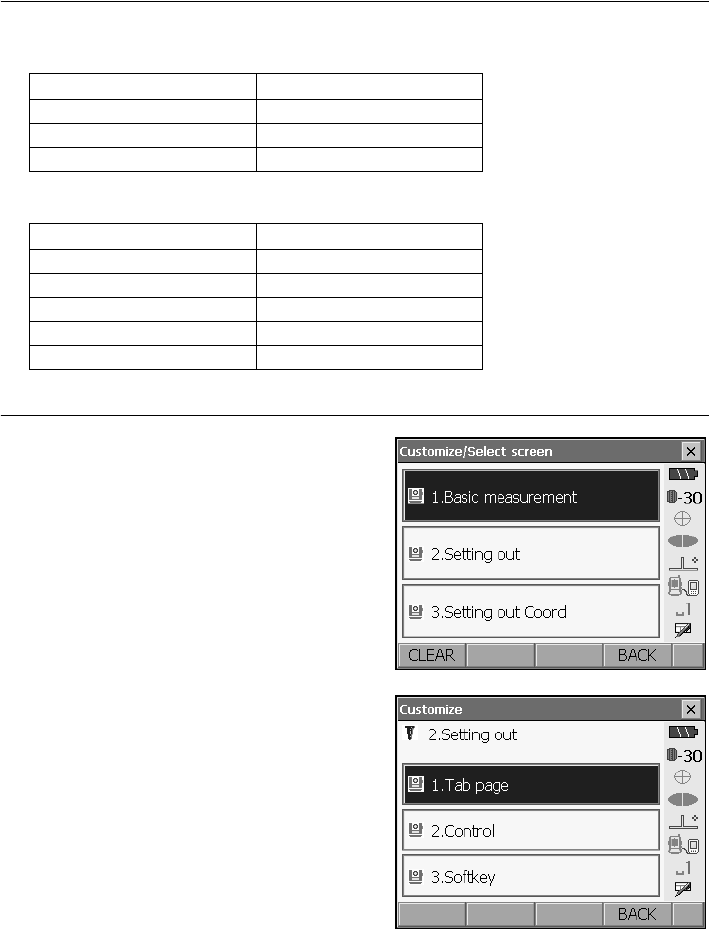
125
21. CHANGING THE SETTINGS
• Setting out
• Setting out Coord.
PROCEDURE Allocating tabs
1. Select "Customize" to display <Customize/Select
screen>.
Select the measurement mode in which you want
to allocate a tab.
Select "Tab page".
Factory settings User-definable tabs
Meas. Meas.
Graphic Graphic
Free
Factory settings User-definable tabs
SHV SHV
NEZ NEZ
Graph1 Graph1
Graph2 Graph2
Free
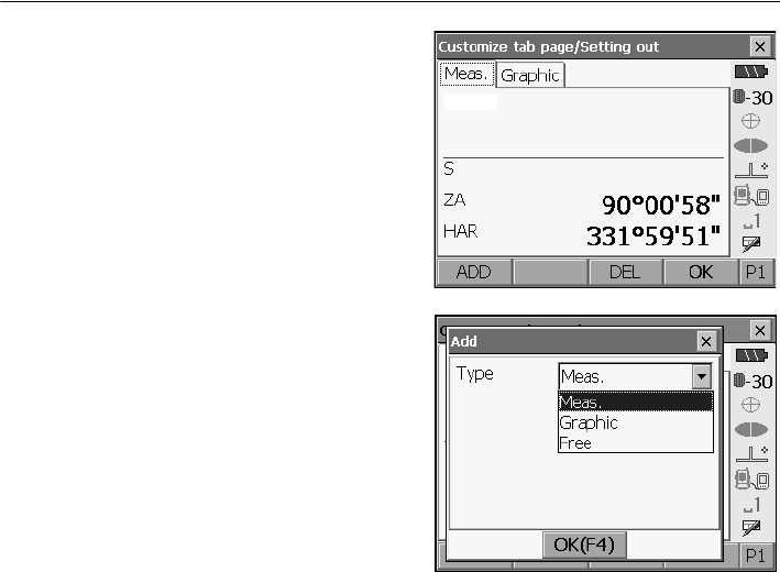
21. CHANGING THE SETTINGS
126
2. Use the softkeys in <Customize tab page> to
allocate the desired tab page layout. Select a tab
type from the "Type" drop-down list.
• Press [ADD] to add the selected tab at the right-
hand side of the screen.
•Press [INS] in the second page to insert the
selected tab in front of the current tab.
•Press [CNFG] in the second page to replace the
current tab with the selected tab.
•Press [DEL] to delete the current tab.
• Tabs, once deleted, cannot be retrieved.
3. Repeat step 2 to perform further tab allocations.
4. Press [OK] to finish allocating tabs. The allocated
tabs are stored in memory and <Customize> is
displayed. The newly allocated tabs appear in the
relevant measurement screen.
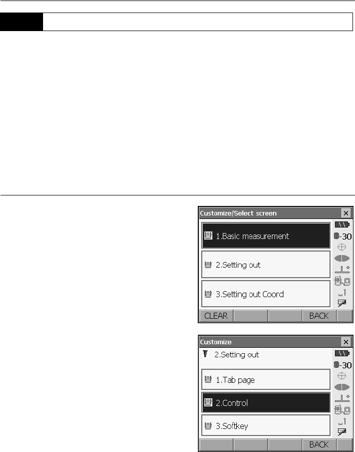
127
21. CHANGING THE SETTINGS
It is possible to customize screen controls in Meas mode to suit the measurement conditions and the
different methods employed by different operators.
• The current screen control settings are retained until they are revised again, even when the power
is cut off.
•Press [CLEAR] in <Customize/Select screen> to return all customized configurations to their
previous settings.
• Screen
control
s cannot be set for the Graphic tab.
• When screen control settings are recorded and registered, the previously recorded settings are
cleared.
PROCEDURE
Customizing
screen controls
1. Select "Customize" to display <Customize/Select
screen>.
Select the measurement mode in which you want
to customize screen controls.
Select "Control".
21.5 Customizing Screen Controls
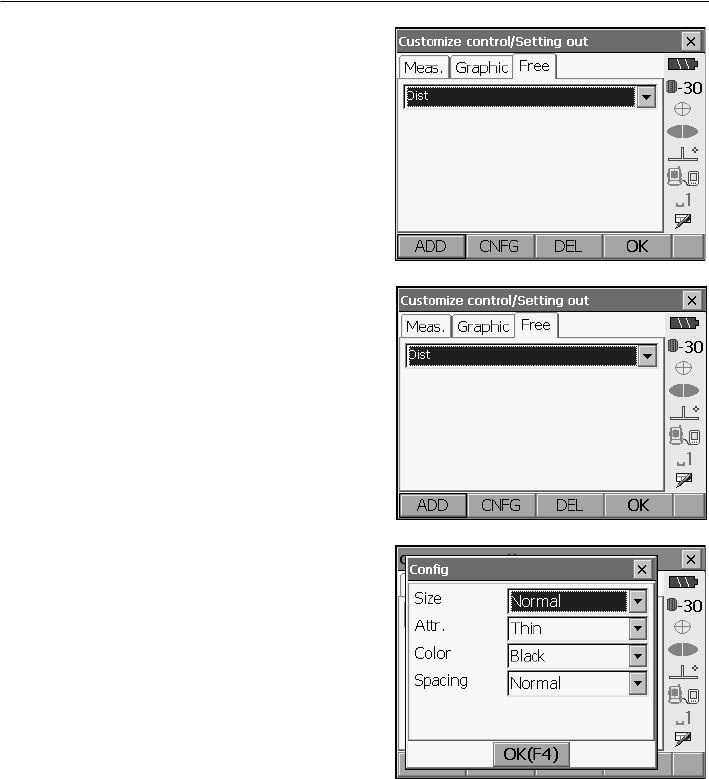
21. CHANGING THE SETTINGS
128
2. Press [ADD] to add a control drop-down list.
• Press [DEL] to delete the selected control.
• Controls, once deleted, cannot be retrieved.
3. Select a screen control from the list.
4. Press [CNFG] to set the size, thickness, color
and spacing of the font.
5. Repeat steps 2 to 4 to customize more screen
controls.
6. Press [OK] to finish customizing screen controls.
The modifications are stored in memory and
<Customize> is displayed. The modifications are
reflected in the relevant screens.

129
21. CHANGING THE SETTINGS
It is possible to allocate the softkeys in Meas mode to suit the measurement conditions. It is possible
to operate the SRX efficiently because unique softkey allocations can be preset to suit various
applications and the ways that different operators handle the instrument.
• The current softkey allocations are retained until they are revised again, even when the power is cut
off.
•Press [CLEAR] in <Customize/Select screen> to return all customized configurations to their
previous settings.
• When softkey allocations are recorded and registered, the previously recorded key settings are
cleared.
●The following are the softkey allocations when the SRX was shipped.
(SHV and SHVdist tabs of <Basic measurement>)
Page 1 [AT On] [MOTOR] [0SET] [DIST]
Page 2 [SRCH] [EDM] [H.ANG] [COORD]
Page 3 [OFFSET] [RESEC] [REM] [S-O]
(Meas. tab of <Setting out>)
Page 1 [AT On] [/shvR] [H.ROTA] [DIST]
Page 2 [CNFG] [ --- ] [ --- ] [ --- ]
Page 3 [ --- ] [ --- ] [ --- ] [ --- ]
(SHV and NEZ tabs of <Set out Coords>)
Page 1 [ OK ] [ AT On ] [H.ROTA] [DIST]
Page 2 [ --- ] [ --- ] [ --- ] [ --- ]
Page 3 [ --- ] [ --- ] [ --- ] [ --- ]
●The following functions can be allocated to the softkeys.
[ --- ] : No functions set
[DIST] : Distance and angle measurement
[H.ROTA] : Rotate SRX to the entered horizontal angle
[CNFG] : Set motor drive operation functions (search accuracy, search offset, A.T. setting,
search method, search area)
[/SHV] : Switches Distance input mode between slope distance (S)/horizontal distance (H)/
height difference (V). The capitalized letter in the softkey indicates the currently
selected mode.)
[/SHVR] : Switches Distance input mode between slope distance (S)/horizontal distance (H)/
height difference (V)/REM (R). The capitalized letter in the softkey indicates the
currently selected mode.
[0SET] : Set horizontal angle to 0°
[H.ANG] : Set required horizontal angle
[R/L] : Select horizontal angle right/left. The capitalized letter in the softkey indicates the
currently selected mode.
21.6 Allocating Key Functions
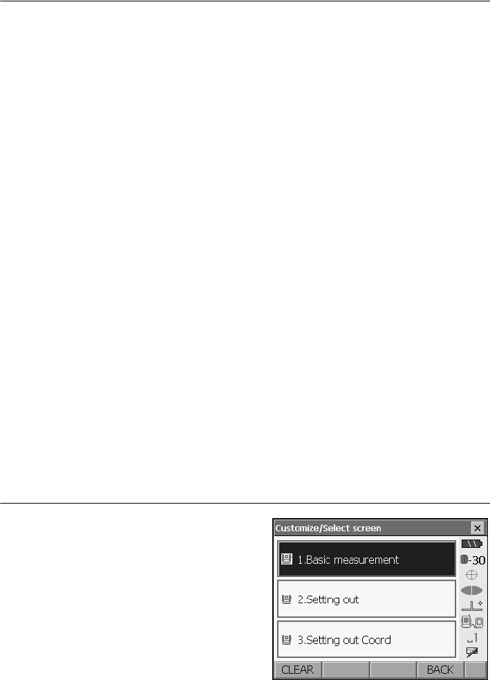
21. CHANGING THE SETTINGS
130
[ZA / %] : Switch between zenith angle/slope in %. The capitalized letter in the softkey indicates
the currently selected mode.
[HOLD] : Hold horizontal angle/release horizontal angle
[RCL] : Display final measurement data
[HV out] : Output angle measurement results to an external device
[HVD out] : Output distance and angle measurement results to an external device
[ft/M] : Switch distance units between meters/feet
[HT] : Set the instrument station height and target height
[AIM] : Return signal
[TILT] : Display tilt angle
[MOTOR] : SETTINGS mode Motor tab
[TURN] : Rotates SRX 180°
[SRCH] : Automatically sights the center of the target
[RC] : Rotate in the direction specified by the On-demand Remote Control system
[<-RC] : Rotate in a counterclockwise direction (from the point of view of the RC Controller)
[RC->] : Rotate in a clockwise direction (from the point of view of the RC Controller)
[RC Cont] : Nullify the current measurement position and continue Turning operation
[JOG] : Fine rotation around vertical and horizontal axes
[AT On] : Start Auto Tracking
[EDM] : EDM settings
[MENU] : Display <Menu> (coordinate measurement, setting out measurement, offset
measurement, REM measurement, missing line measurement, Resection, area
calculation)
[COORD] : Coordinates measurement
[S-O] : Setting-out measurement
[OFFSET] : Offset measurement
[A-OFS] : Angle offset menu
[D-OFS] : Distance offset menu
[2D-OFS] : Offset/2D menu
[MLM] : Missing line measurement
[REM] : REM measurement
[RESEC] : Resection measurement
[AREA] : Surface area measurement
PROCEDURE Allocating a softkey
1. Select "Customize" to display <Customize/Select
screen>.
Select the measurement mode in which you want
to allocate a softkey.
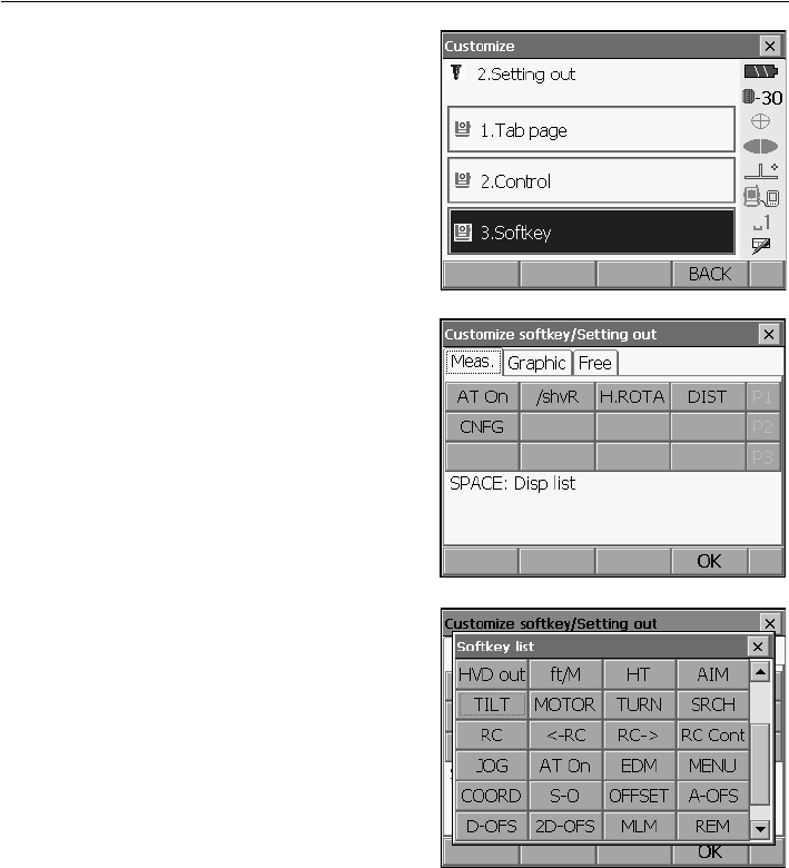
131
21. CHANGING THE SETTINGS
Select "Softkey".
2. Select the desired tab. All softkeys currently
allocated to each page of that tab are displayed.
3. Select the softkey whose allocation you want to
change. Tapping a softkey, or pressing {SPACE}
when the cursor is aligned with a softkey, will
display <Softkey list>.
4. Select the desired softkey from <Softkey list> to
allocate to the position specified in step 3.
5. Repeat steps 2 to 3 to perform further key
allocations.
6. Press [OK] to finish allocating keys. The allocated
keys are stored in memory and <Customize> is
displayed. The newly allocated keys appear in the
relevant measurement screen.
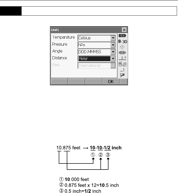
21. CHANGING THE SETTINGS
132
Items set and options (*: Factory setting)
Temperature: Celsius*/Farenht
Pressure: hPa/mmHg/InchHg
Angle: Degree (DDD.MMMSS)*/Gon/Mil
Distance: Meter*/Feet/Inch
Feet (only displayed when "Feet" or "Inch" selected above):
International*/US
Inch (Fraction of an inch)
“Fraction of an inch” is the unit used in the United States and expressed like the following
example.
• Even if “inch” is selected in this setting, all the data including the result of area calculation are
output in “feet” and all the distance values must be input in “feet”. In addition, when the “inch”
display exceeds the range, it is displayed in “feet”.
21.7 Units
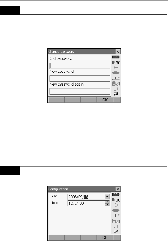
133
21. CHANGING THE SETTINGS
Setting a password allows you to protect important information such as measurement data and e-mail
addresses.
No password was set when the SRX was shipped. When setting a password for the first time, leave
the "Old password" box blank.
When a password has been set, the password screen will appear when the SRX is powered ON. Input
the password to continue.
Items set
Old password: Input current password
New password: Input the new password
New password again: Input the new password again
• Password can be up to 16 characters in length. Input characters will be displayed as asterisks.
• To deactivate the password function, perform the new password setting procedure but enter a
"space" in the "New password" box.
• The password function will not be canceled when a cold boot is performed.
• An e-mail address is necessary when using the Series SRX SFX Dial-Up Program.t
21.8 Changing Password
21.9 Date and Time
21. CHANGING THE SETTINGS
134
Items set
Date: Manually input date or select from the drop-down
calendar. Pressing {SPACE} will increment the
selected section by 1.
Time: Manually input time or set using []/[].
Date and Time
The SRX includes a clock/calendar function.
Perform a cold boot to return all items to factory settings. A cold boot will not erase surveying data
in Program mode (SDR). However, if the data in the memory is important, BE SURE TO TRANSFER
IT TO A PERSONAL COMPUTER BEFORE PERFORMING A COLD BOOT.
To perform a cold boot, while holding {F3}, {F1}, and {BACKSPACE}, press
{}
. The following
message appears.
"All Data, Settings will be cleared. Are you sure?"
Press [YES] to continue. Press {ESC} to cancel.
After
[YES]
is pressed the instrument powers ON as normal.
•The password function will not be canceled.
21.10 Restoring Default Settings

135
22.WARNING AND ERROR MESSAGES
The following is a list of the error messages displayed by the SRX and the meaning of each message.
If the same error message is repeated or if any message not shown below appears, the instrument
has malfunctioned. Contact your Sokkia agent.
Backup battery dead. Clock display may no longer be correct.
The voltage supplied by the lithium battery either declines or is completely discharged. Ask your
Sokkia agent to replace the battery for you.
Bad condition
The air is shimmering a lot, etc., measuring conditions are poor.
The center of the target cannot be sighted.
Resight the target.
Unsuitable distance measurement conditions when reflectorless measurement is set. When
reflectorless measurement is set, distance cannot be measured because the laser beam is
striking at least two surfaces at the same time.
Choose a single surface target for distance measurement.
Precautions for setting prism: ""11. TARGET SIGHTING""
Calculation error
During resection measurement the same point is registered multiple times. Set another known
point so that the known point coordinates do not coincide.
During surface area calculation, conditions necessary for calculations are not met. Check
conditions and try again.
Cannot changing TS <==> SDR!!
Cannot switch to Program mode (SDR).
Perform a warm boot then power ON as normal. If this error message appears frequently, contact
your Sokkia agent.
Device list is full !!
No more Bluetooth devices can currently be registered. Delete unnecessary devices from the list
and try again.
Error: Read Build Info.
Error: Read sysflg
Error: Self check
Press [OK] to cancel the message. If this error message appears frequently, contact your Sokkia
agent.
Incorrect password.
Input password does not match set password. Input correct password.
Input device name !!
Bluetooth device name not input. Input device name and complete device registration.
Input over 3 letters !

22. WARNING AND ERROR MESSAGES
136
The input password consists of less than 3 characters. Input a password at least 3 characters in
length.
Job data is not developed. Or job may have broken.
Program mode (SDR) JOB data lost or cannot be read in. Create JOB data again.
Motor error EXXX
A problem has occurred with the motor drive and operation stops.
Power the SRX OFF then ON to correct the problem.
If this error message appears frequently, contact your Sokkia agent.
Need base pt. obs
During REM measurement, the observation of the target was not completed normally.
Reset and sight the prism and perform measurement again.
Need 1st obs
During missing line measurement, the observation of the starting position was not completed
normally.
Sight the starting position accurately and press [OBS] to perform the measurement again.
New password Diff.
During new password setting, the passwords input twice are different. Input
new password twice correctly.
No data
When searching for or reading in coordinate data or searching for code data, the search stopped
either because the item in question does not exist or the data volume is large.
No solution
The calculation of the instrument station coordinates during resection does not converge.
Access the results and if necessary, perform the observations again.
Not exist point
When reading in coordinate values during instrument station registration etc., there is no
coordinates data registered in the memory and in the selected JOB. Register coordinate data first.
Out of range
During gradient % display, the display range (less than ± 1000%) has been exceeded.
During REM measurement, either the vertical angle has exceeded horizontal ±89° or the
measured distance is greater than 9999.999m.
Install the instrument station far from the target.
The instrument station coordinates calculated during resection are too high.
Perform the observation again.
During area calculation, results exceeded the display range.
Reflectorless not supported !!
Automatic sighting cannot be performed with in reflectorless mode.
Use the prism to carry out automatic sighting.

137
22. WARNING AND ERROR MESSAGES
Remote Control communication err !!
Communication between the On-demand Remote Control system RC controller and the SRX
failed. Check the status (communications setup, power supply, cable connections etc.) of the RC
controller, wireless modem and cables.
Sheet not supported !!
Automatic sighting cannot be performed with the sheet.
Use the prism to carry out automatic sighting.
Signal off
The reflected light is not observed when distance measurement begins. Or, during measurement,
the reflected light has weakened or is blocked.
Either sight the target again or, when using a reflective prism, increase the number of reflective
prisms.
Target not found !!
The prism cannot be found within the automatic sighting range.
Reset and sight the prism and perform measurement again.
Temp Rnge OUT
SRX is outside useable temperature range and accurate measurement cannot be performed.
Repeat measurement within the appropriate temperature range.
Tilt over range !!
The tilt angle exceeds the tilt angle compensation range of the sensor.
Sight again within ±3'.
Time out !!
Measurement is not carried out in the allotted time.
Reset and sight the prism and perform measurement again.
When designating the angle of rotation or automatically sighting the prism, there is a problem with
the positioning of the prism or the operation of the instrument and measurement is not obtained
within the fixed time.
Check the positioning of the instrument and prism and perform measurement again.
If observation is still not possible, sight the target manually.
When the telescope turns to zenith/nadir, it is not possible to search !!
The SRX cannot perform a search during Auto Pointing or Auto Tracking when the telescope is
directed to the zenith or nadir angle. Check the telescope position and perform the operation
again.
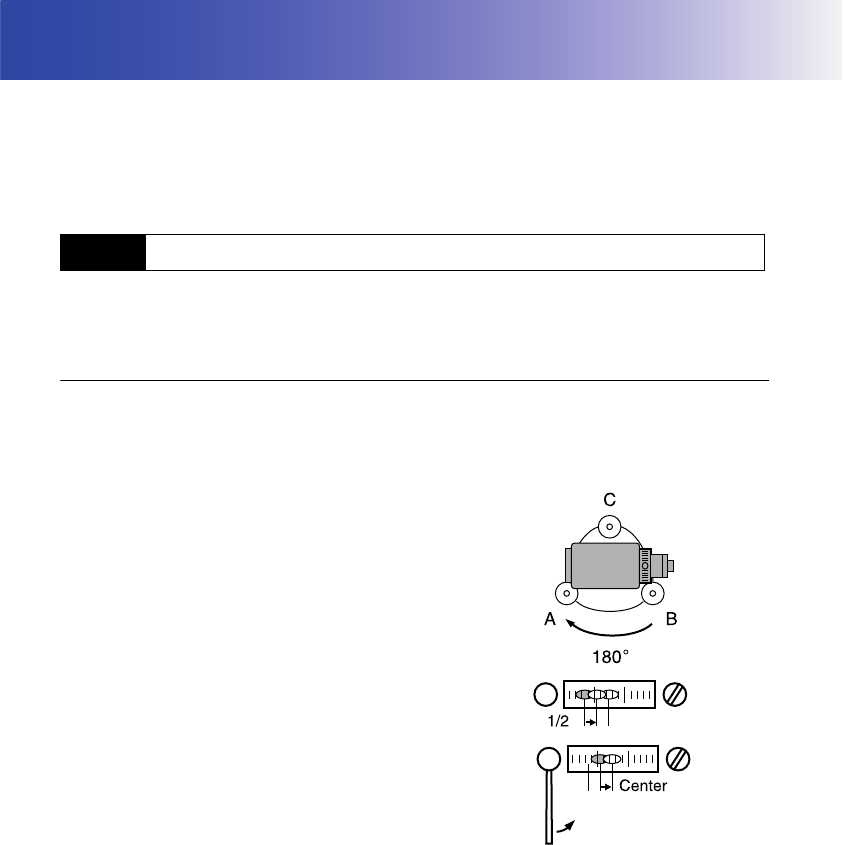
138
23.CHECKS AND ADJUSTMENTS
SRX is a precision instrument that requires fine adjustments. It must be inspected and adjusted before
use so that it always performs accurate measurements.
• Always perform checking and adjustment in the proper sequence beginning from "23.1 Plate Level"
to "23.8 Additive Distance Constant".
• In addition, the instrument should be inspected with special care after it has been stored a long time,
transported, or when it may have been damaged by a strong shock.
The bubble tube is made of glass, so it is sensitive to temperature changes or to shock. Check and
adjust it as outlined below.
PROCEDURE Checking and adjusting
1. Level the instrument and check the position of the
bubble of the plate level.
"9.2 Levelling", steps 3 to 5
2. Turn the upper part of the SRX through 180° and
check the bubble position.
If the bubble is still centered, no adjustment is
necessary.
If the bubble is off-center, adjust as follows.
3. Correct half of the bubble displacement using
levelling foot screw C.
4. Correct the remaining half of the displacement by
using the adjustment pin to rotate the plate level
adjustment screw.
When the plate level adjustment screw is turned in
the counterclockwise direction, the bubble moves
in the same direction.
5. Rotate the top of the instrument and continue
adjustments until the bubble remains centered for
any position of the upper part.
If the bubble does not move to the center even
when the adjustment has been repeated, ask your
Sokkia agent to adjust it.
23.1 Plate Level
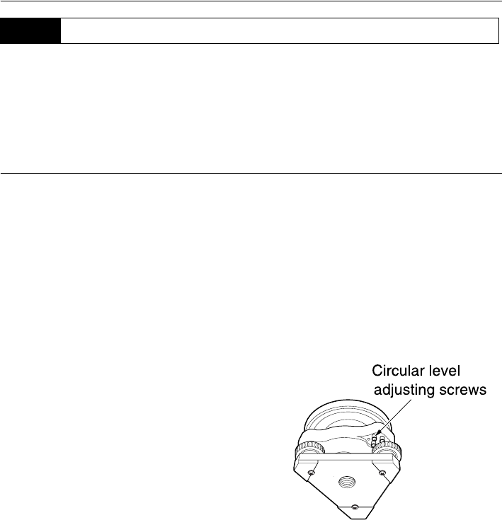
139
23. CHECKS AND ADJUSTMENTS
Check and adjust it as outlined below.
• Be careful that the tightening tension is identical for all the adjusting screws.
• Also, do not over-tighten the adjusting screws as this may damage the circular level.
PROCEDURE Checking and adjusting
1. Perform the plate level inspection and adjustment
or carefully use the plate level to level the
instrument.
"9.2 Levelling", steps 1 to 2
2. Check the position of the bubble of the circular
level.
If the bubble is not off-center, no adjustment is
necessary.
If the bubble is off-center, perform the following
adjustment.
3. First confirm the off-center direction.
Use the adjusting pin to loosen the circular level
adjustment screw on the side opposite to the
direction the bubble is displaced to move the
bubble to the center.
4. Adjust the adjusting screws until the tightening
tension of the three screws is the same to align
the bubble in the middle of the circle.
23.2 Circular Level
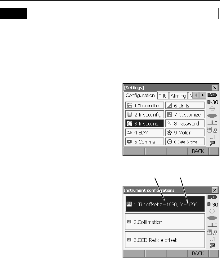
23. CHECKS AND ADJUSTMENTS
140
If the tilt angle shown on the display shifts from tilt angle 0° (zero point), the instrument is not correctly
levelled. This will adversely affect angle measurement.
Perform the following procedure to cancel the tilt zero point error.
PROCEDURE Checking and adjusting
1. Carefully level the SRX. If necessary, repeat the
procedures to check and adjust the bubble levels.
2. Select "Inst. cons." in <Configuration>
3. Select "Tilt offset".
23.3 Tilt Sensor
correction constant
in the X (horizontal)
direction
correction constant
in the Y (vertical)
direction
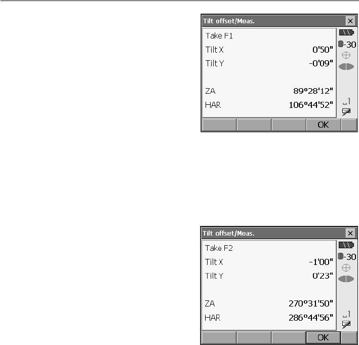
141
23. CHECKS AND ADJUSTMENTS
4. Wait a few seconds for the display to stabilize,
then read the current tilt angle in the X (sighting)
direction and Y (horizontal axis) direction.
5. Press [OK]. The top of the instrument and
telescope automatically rotate 180° and the
horizontal angle is set to 0°.
6. Wait a few seconds for the screen to stabilize,
then read the automatically compensated angles
X2 and Y2.
7. In this state, calculate the following offset values
(tilt zero point error).
Xoffset = (X1+X2)/2
Yoffset = (Y1+Y2)/2
If one of the offset values (Xoffset, Yoffset)
exceeds ±10", adjust the value using the following
procedure.
When the offset value falls within the range ±10",
adjustment is not necessary.
Press {ESC} to return to <Instr. const>.
8. Press [OK] to automatically rotate the top of the
instrument and telescope through 180°.
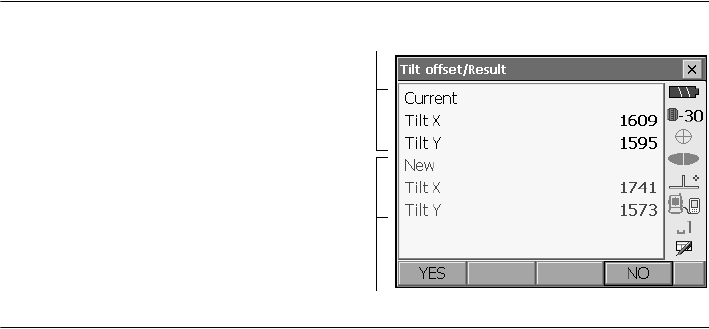
23. CHECKS AND ADJUSTMENTS
142
9. Confirm that the values are in the adjustment
range.
If both correction constants are within the
range 1600 ±120, select [YES] to renew the
correction angle. <Instrument configurations>
is restored. Continue to step 11.
If the values exceed the adjustment range,
select [NO] to cancel the adjustment and
restore <Instrument configurations>. Contact
your Sokkia agent to perform the adjustment.
PROCEDURE Recheck
10. Select "Tilt offset".
11. Wait a few seconds for the display to stabilize,
then read the automatically compensated angles
X3 and Y3.
12. Press [OK] to automatically rotate the top of the
instrument and telescope through 180°.
13. Wait a few seconds for the display to stabilize,
then read the automatically compensated angles
X4 and Y4.
14. In this state, the following offset values (tilt zero
point error) are calculated.
Xoffset = (X3+X4)/2
Yoffset = (Y3+Y4)/2
When both offset values fall within the range ±10",
adjustment is completed.
Press {ESC} to return to <Instr. const>.
If one of the offset values (Xoffset, Yoffset)
exceeds ±10", repeat the check and adjustment
procedures from the beginning. If the difference
continues to exceed ±10" after repeating the
check 2 or 3 times, have your Sokkia agent
perform the adjustment.
Results for target point
Results for offset point
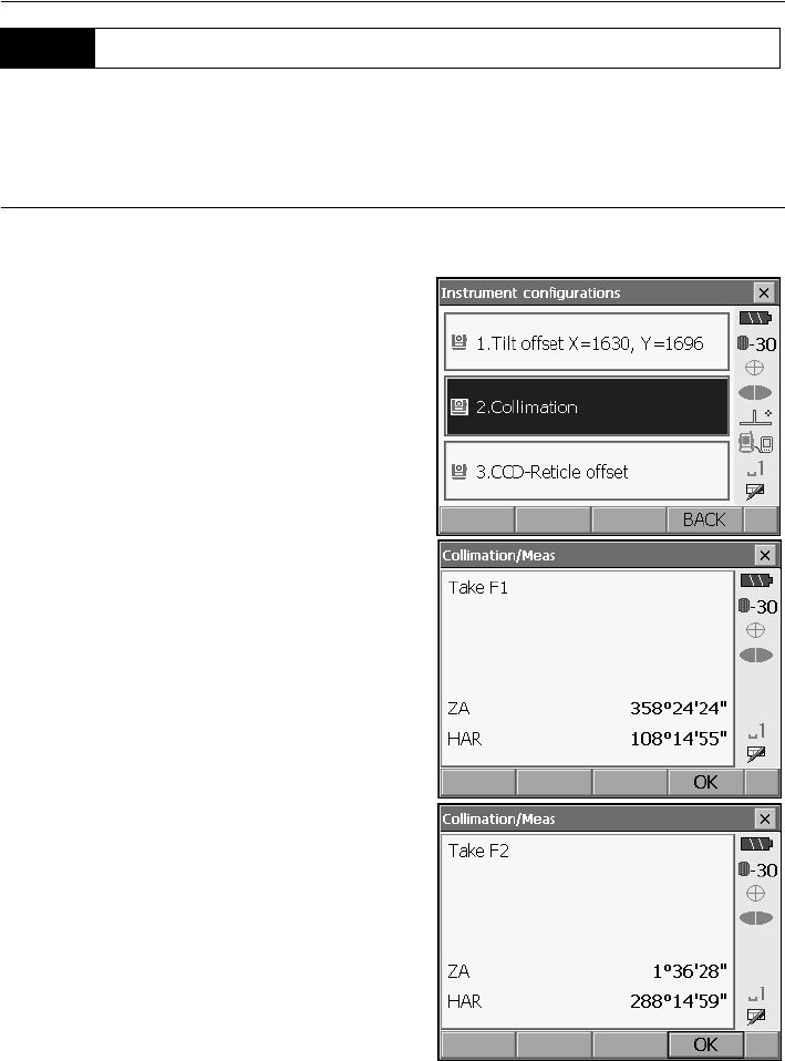
143
23. CHECKS AND ADJUSTMENTS
With this option you can measure collimation error in your instrument so that the SRX can correct
subsequent single face observations. To measure the error, make angular observations using
both faces.
PROCEDURE
1.
Select "Inst. cons." in <Configuration>.
2. Select "Collimation".
3. Sight the reference point in Face 1 and press
[OK]. Telescope rotates and vertical circle is
indexed.
•Do not look through the telescope eyepiece
while the motor drive is in operation. An eye
could be struck by the telescope and cause
injury.
4. Sight the reference point in Face 2 and press
[OK].
23.4 Collimation
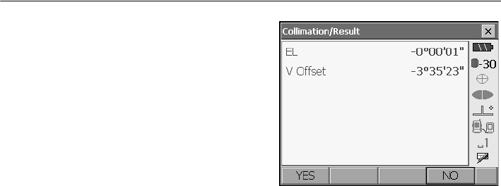
23. CHECKS AND ADJUSTMENTS
144
5. Press [YES] to set the constant.
• Press [NO] to discard the data and return to
<Instrument configurations>.
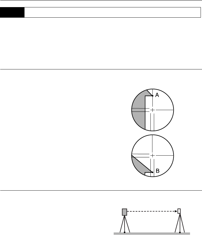
145
23. CHECKS AND ADJUSTMENTS
With this option you can check the perpendicularity of the reticle and the horizontal/vertical positions
of reticle lines.
• Check the telescope reticle by manually sighting the target.
PROCEDURE Check 1: Perpendicularity of the reticle to the horizontal axis
1. Carefully level the instrument.
2. Align a clearly visible target (the edge of a roof for
example) on point A of the reticle line.
3. Use the jogging knobs to align the target to point
B on a vertical line.
If the target moves parallel to the vertical line,
adjustment is unnecessary. If its movement
deviates from the vertical line, have your Sokkia
service representative adjust it.
PROCEDURE Check 2: Vertical and horizontal reticle line positions
1. Carefully level the instrument.
2. Install a target at a point about 100m in the
horizontal direction from the SRX.
3. While the Meas mode screen is displayed and the
telescope is in face left, sight the center of the
target and read out the horizontal angle A1 and
the vertical angle B1.
Example:
Horizontal angle A1= 18° 34' 00"
Vertical angle B1 = 90° 30' 20"
23.5 Reticle

23. CHECKS AND ADJUSTMENTS
146
4. While the telescope is in face right, sight the
center of the target and read out the horizontal
angle A2 and the vertical angle B2.
Example:
Horizontal angle A2 = 198° 34' 20"
Vertical angle B2 = 269° 30' 00"
5. Do the calculations: A2-A1 and B2+B1
If A2-A1 is within 180°±20″and B2(B1 is within
360°±20″, adjustment is unnecessary.
Example:A2-A1 (Horizontal angle)
=198° 34' 20"- 18° 34' 00"
=180° 00' 20"
B2-B1 (Vertical angle)
=269° 30' 00" + 90° 30' 20"
=360° 00' 20"
If the difference is large even after repeating the
check 2 or 3 times, have your Sokkia service
representative perform the adjustment.
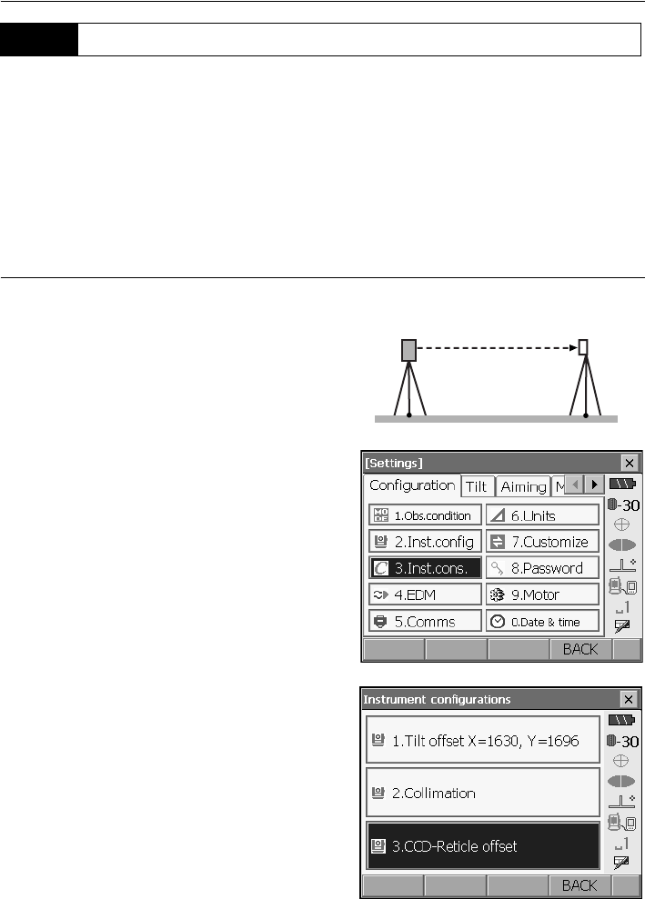
147
23. CHECKS AND ADJUSTMENTS
The internal CCD sensor is used for automatic sighting. The offset value is set to correct the position
of the CCD sensor in relation to the telescope reticle, but if for whatever reason the telescope reticle
and CCD camera become misaligned, automatic sighting of the center of the prism cannot be
performed correctly. Check and adjust it as outlined below.
• Perform check and adjustment in weak sunlight and no scintillation.
• It may take up to 20 seconds for an offset value based on the measurement results to appear .
PROCEDURE Checks and adjustments
1. Carefully level the instrument.
2. Position the prism in a horizontal direction
approximately 50 meters from the SRX.
3. Select "Inst.cons." in <Configuration>.
4. Select "CCD-Reticle offset".
23.6 CCD reticle
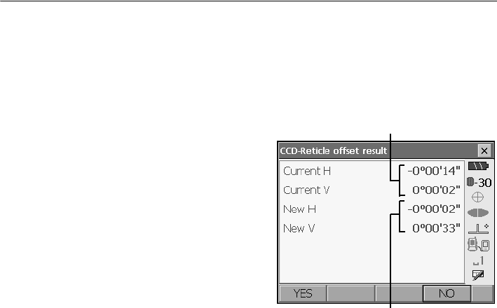
23. CHECKS AND ADJUSTMENTS
148
5. Use manual sighting to accurately sight the
target.
"11.3 Manually Sighting the Target"
6. Press [OK].
Press [STOP] to stop the measurement.
7. Offset value (H, V) is obtained from the set offset
value (H, V) and the measurement results. The
offset value is a constant value that indicates the
number of degrees of misalignment between the
center of the telescope reticle and the center of
the CCD sensor. If the offset value obtained from
the measurement result is significantly larger than
the set offset value, press [ESC] and resight the
target.
If the offset value (H, V) obtained from the
measurement results continues to be significantly
large after repeated checks, adjustment is
necessary. Go to step 8.
If one of the offset values exceeds the range, an
error message appears on the screen. Contact
your Sokkia agent to perform the adjustment.
8. Press [OK] to renew the offset value.
• Press [INIT] to return to the default settings.
S
et o
ff
set va
l
ue
Offset value obtained from
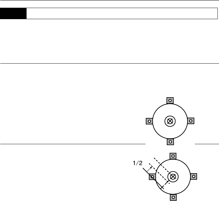
149
23. CHECKS AND ADJUSTMENTS
• Be careful that the tightening tension is identical for all the adjusting screws.
• Also, do not over-tighten the adjusting screws as this may damage the circular level.
PROCEDURE Checking
1. Carefully level the SRX and center a surveying
point precisely in the reticle of the optical
plummet.
2. Turn the upper part through 180° and check the
position of the surveying point in the reticle.
If the surveying point is still centered, no
adjustment is necessary.
If the surveying point is no longer centered in the
optical plummet, perform the following adjustment.
PROCEDURE Adjustment
3. Correct half the deviation with the levelling foot
screw.
4. Remove the optical plummet reticle cover.
23.7 Optical Plummet
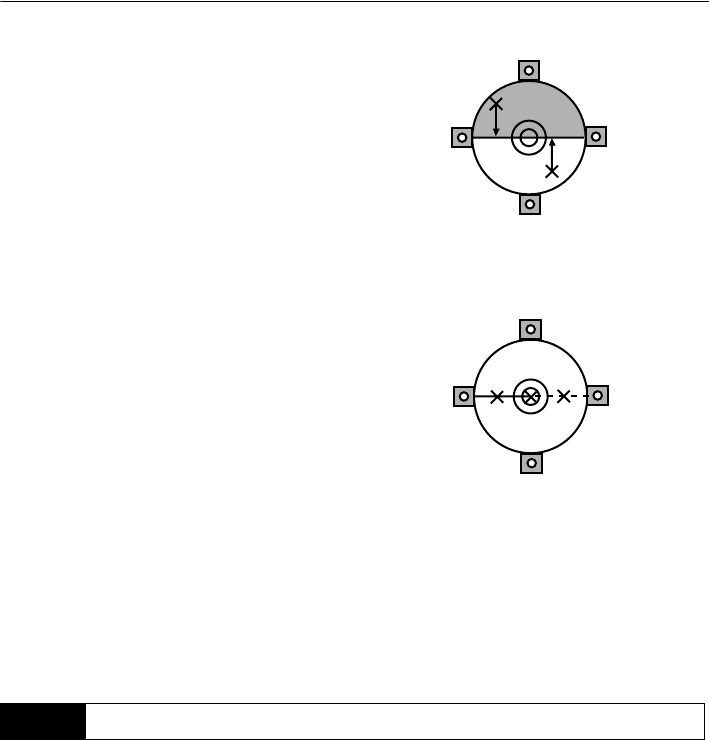
23. CHECKS AND ADJUSTMENTS
150
5. Use the 4 adjusting screws of the optical plummet
to adjust the remaining half of the deviation as
shown below.
When the surveying point is on the lower (upper)
part of the illustration:
Loosen the upper (lower) adjusting screw slightly,
and tighten the upper (lower) adjusting screw the
same amount to move the surveying point to a
point directly under the center of the optical
plummet.
(It will move to the line in the figure on the right.)
If the surveying point is on the solid line (dotted
line):
Loosen the right (left) adjusting screw slightly and,
tighten the left (right) adjusting screw by the same
amount to move the surveying point to a point in
the center of the optical plummet.
6. Check to make sure that the surveying point
remains centered on the reticle even if the upper
part of the instrument is rotated.
If necessary, perform the adjustment again.
7. Replace the optical plummet reticle cover.
The additive distance constant K of the SRX is adjusted to 0 before delivery. Although it almost never
deviates, use a baseline with a known distance precision to check that the additive distance constant
K is close to 0 several times a year and whenever the values measured by the instrument begin to
deviate by a consistent amount. Perform these checks as follows.
• Errors in setting up the instrument and reflective prism or in sighting the target will influence the
additive distance constant. Be extremely careful to prevent such errors when performing these
procedures.
• Set up so that the instrument height and the target height are identical. If a flat place is not available,
use an automatic level to make sure the heights are identical.
23.8 Additive Distance Constant
4
(3)
3
(4)
1 (2)
2 (1)
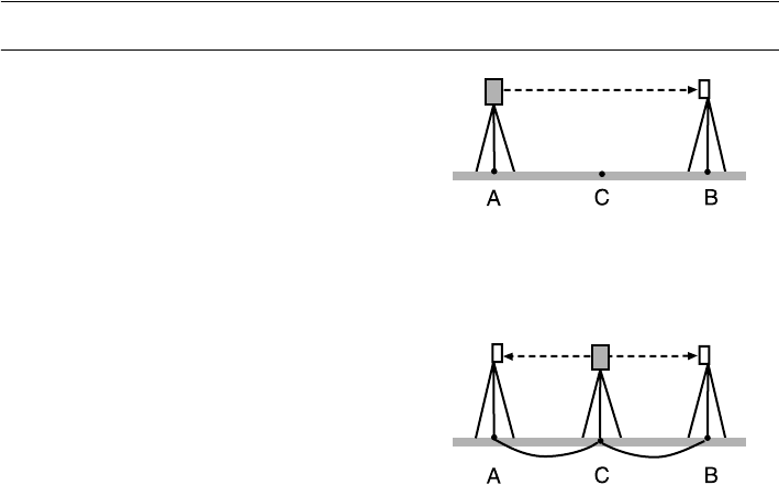
151
23. CHECKS AND ADJUSTMENTS
PROCEDURE Check
1. Find an area of flat ground where two points
100m apart can be selected.
Set up the Instrument at point A and the reflective
prism at point B. Establish a point C half way
between points A and B.
2. Precisely measure the horizontal distance
between point A and point B 10 times and
calculate the average value.
3. Place the SRX at point C directly between points
A and B and set up the reflective prism at point A.
4. Precisely measure the horizontal distances CA
and CB 10 times each and calculate the average
value for each distance.
5. Calculate the additive distance constant K as
follows.
K = AB - (CA+CB)
6. Repeat steps 1 to 5 two or three times.
If the additive distance constant K is within ±3mm
even once, adjustment is unnecessary.
If it always exceeds this range, have your Sokkia
service representative perform an adjustment.
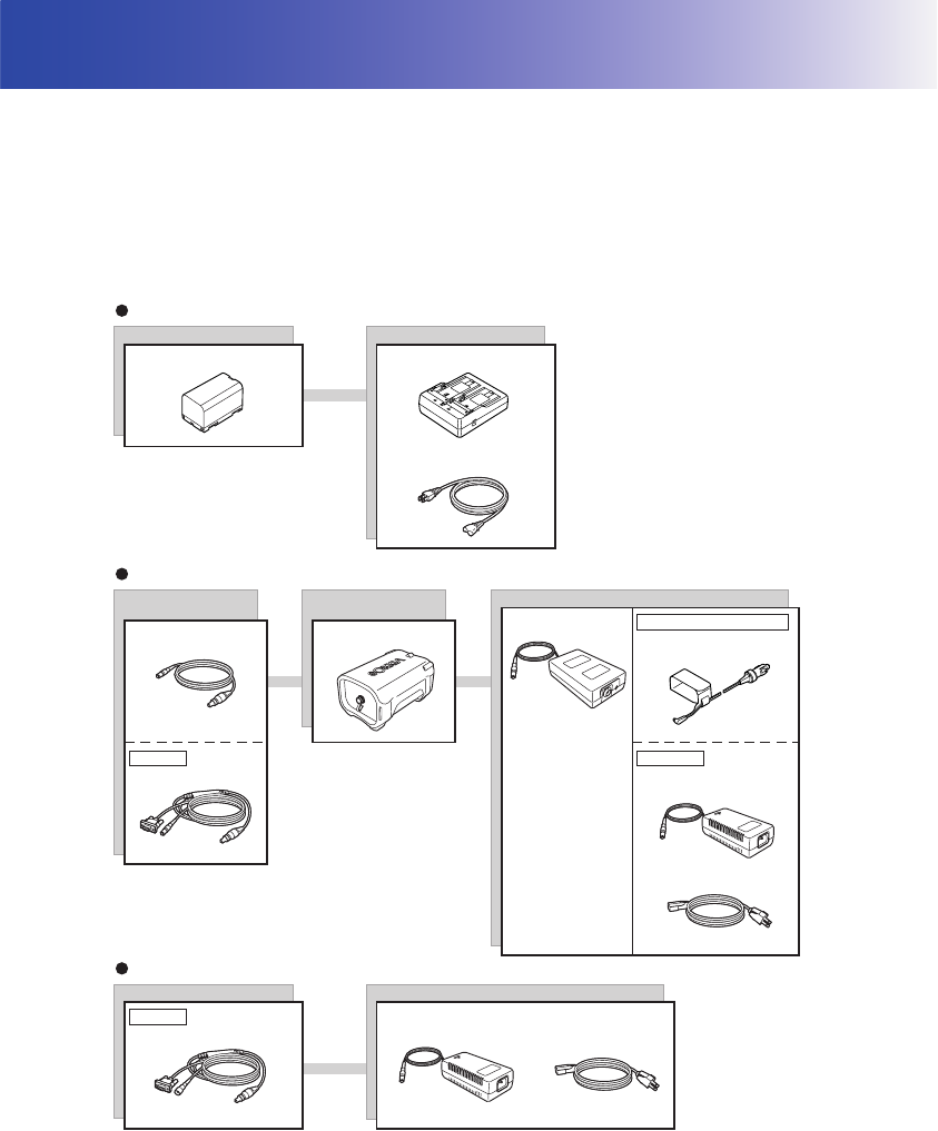
152
24.POWER SUPPLY SYSTEM
Operate your SRX with the following combinations of power equipment.
• When using BDC60/61 and EDC117, mount the BDC58 in place to maintain the balance of the
instrument.
• Never use any combination other than those indicated below. If you do, the SRX could be damaged.
Those indicated by * are standard accessories. Others are optional accessories (sold separately).
By using the Y cable the SRX can perform RS-232C communication (D-sub 9-pin) at the same time
as connecting to an external power source.
EDC121
EDC117
(AC100V)
EDC117
(AC100V to 240V)
CDC71
EDC34
BDC61
(DC7.2V,13Ah)
EDC118
Battery
BDC58* CDC68*
EDC113A/C* (110 to 240 V AC)
EDC113B (110 to 240V AC)
Charger
Charger
Cable for external
battery
Cable for AC adapter
External battery adapter
AC adapter
EDC34
EDC115 (DC12V)
For car cigarette lighter
AC adapter
Battery
External battery
AC adapter
Y cable
EDC120
Y cable
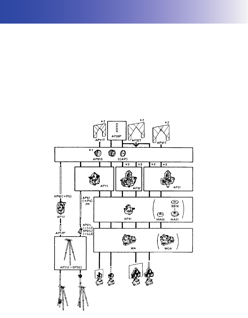
153
25.TARGET SYSTEM
The following are all special accessories (sold separately).
• Because all Sokkia reflecting prisms and accessories have standardized screws, it is possible
to combine these prisms, accessories, etc. according to your objectives.
• Because these targets (*2) are coated with fluorescent paint, they reflect when there is little light.
• When using a reflecting prism equipped with a target for distance and angle measurements, be sure
to direct the reflective prism correctly and sight the center of the prism target accurately.
• Each reflective prism (*1) has its own prism constant value. When changing prisms, be sure to
change the prism constant correction value.
• To use the triple prism assembly AP31 or AP32 as a single prism for short distance measurements,
mount the single reflective prism AP01AR in the center mounting hole of the prism holder.
series
AP01AR
APS12R-AR APS11R-AR
APS12R-AR APS11R-AR APS34R-AR
Prism system tribrachs
Prism height adaptors
Prism holders
Prism
Targets
APS31R-AR
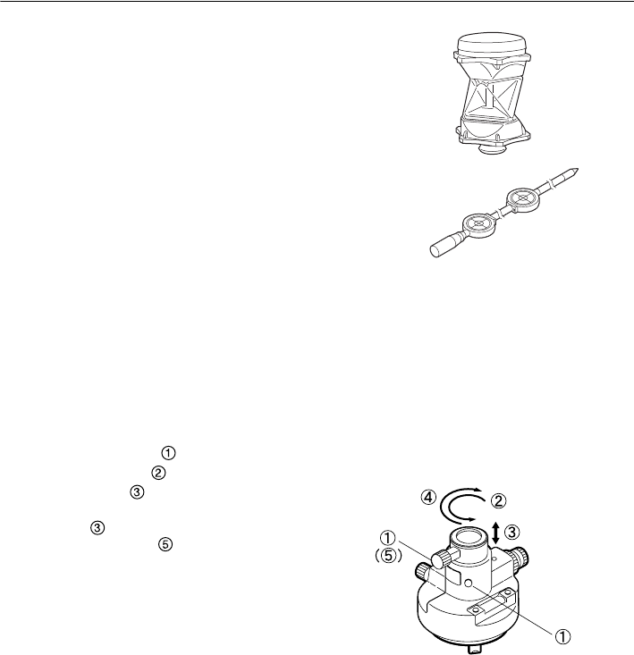
25. TARGET SYSTEM
154
●360° Prism (ATP1)
This column-shaped prism reduces the possibility
of "losing" the prism during Auto Tracking
measurement.
2-point target (2RT500-K)
This target is used for two-distance offset
measurement.
Prism constant: 0
●Instrument height adaptor (AP41)
This device is used to adjust the height of the
target.
• The height of the AP41 instrument height
adaptor can be adjusted using two fixing screws.
When used with the SRX, make sure that the
instrument height "245" (mm) is displayed in the
instrument height adjustment window.
• Loosen the screws and rotate SRX
counterclockwise .
Move the part up or down until the desired
instrument height is displayed in the adjustment
window , then rotate SRX clockwise and
tighten the screws .
• Adjust the level of the AP41 instrument height
adaptor following the checking and adjustment
methods of plate level.
"23.1 Plate Level"
• Adjust the optical plummet of the AP41
instrument height adaptor following the checking
and adjustment methods of optical plummet.
•"23.7 Optical Plummet"
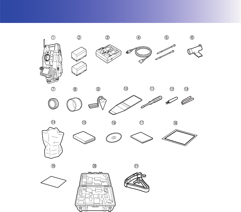
155
26.STANDARD EQUIPMENT
Please verify that all equipment is included.
1 SRX main unit . . . . . . . . . . . . . . . . . . . 1
2 Battery (BDC58) . . . . . . . . . . . . . . . . . 2
3 Battery charger (CDC68) . . . . . . . . . . 1
4 Power cable (EDC113) . . . . . . . . . . . . 1
5 Stylus pen . . . . . . . . . . . . . . . . . . . . . . 2
6 Tubular compass (CP9) . . . . . . . . . . . 1
7 Lens cap . . . . . . . . . . . . . . . . . . . . . . . 1
8 Lens hood . . . . . . . . . . . . . . . . . . . . . . 1
9 Plumb bob. . . . . . . . . . . . . . . . . . . . . . 1
10 Tool pouch. . . . . . . . . . . . . . . . . . . . . . 1
11 Screwdriver . . . . . . . . . . . . . . . . . . . . . 1
12 Lens brush . . . . . . . . . . . . . . . . . . . . . 1
13 Adjusting pin . . . . . . . . . . . . . . . . . . . . 1
14 Cleaning cloth . . . . . . . . . . . . . . . . . . . 1
15 Vinyl cover . . . . . . . . . . . . . . . . . . . . . 1
16 Operator's manual . . . . . . . . . . . . . . . 1
17 CD-ROM . . . . . . . . . . . . . . . . . . . . . . . 1
(Series SRX SDR Software Reference
Manual, SFX Dial-Up Program
Explanations, Quick Manual)
18 Quick Manual . . . . . . . . . . . . . . . . . . . 1
19 Laser caution sign-board . . . . . . . . . . 1
20 Carrying case (SC219) . . . . . . . . . . . . 1
21 Carrying strap . . . . . . . . . . . . . . . . . . 1
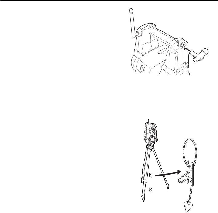
26. STANDARD EQUIPMENT
156
●Tubular compass (CP9)
Slide the tubular compass into the tubular com-
pass slot, loosen the clamp screw, then rotate the
top part of the instrument until the compass nee-
dle bisects the index lines. The telescope's face 1
sighting direction in this position will indicate mag-
netic north. After use, tighten the clamp and
remove the compass from the slot.
• The tubular compass is susceptible to the influence
of nearby magnets or metal. Such influence could
cause it to fail to accurately indicate magnetic north.
Do not use magnetic north as indicated by this
compass for base line surveying.
●Plumb bob
The plumb bob can be used to set up and center
the instrument on days when there is little wind.
To use the plumb bob, unwind its cord, pass it
through the cord grip piece as shown in the figure
to adjust its length, then suspend it from the hook
attached to the centering screw.
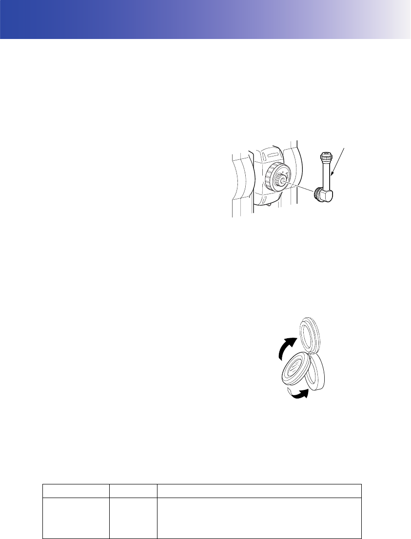
157
27.OPTIONAL ACCESSORIES
The following are optional accessories which are sold separately from the SRX.
Power supply and target optional accessories: "24. POWER SUPPLY SYSTEM", "25. TARGET
SYSTEM".
●Telescope eyepiece lens (EL7)
Magnification: 40X
Field of view:
1° 20
'
●Diagonal eyepiece (DE27)
The diagonal eyepiece is convenient for
observations near the nadir and in narrow spaces.
Magnification: 30X
After removing the handle from the SRX loosen
the attachment screw to remove the telescope
eyepiece. Then screw the diagonal lens into place.
Handle removal method: "4.2 Parts of the
Instrument Removing the handle (RC-TS3)"
• Do not perform automatic vertical rotation of the
telescope when using the diagonal eyepiece.
The diagonal eyepiece may strike the SRX
causing damage.
●Solar filter (OF3A)
When sighting targets where glare is present,
solar observations for example, attach it to the
objective lens of the SRX to protect its interior and
the eyes of its operator. The filter part can be
flipped up without being removed.
• Do not perform automatic vertical rotation of the
telescope when using the solar filter. The solar
filter may strike the SRX causing damage.
●Interface cable
Connect between the SRX and the host computer in combination with EDC120+DOC128.
Computer Cable Notes
IBM PC/AT or
compatible DOC26
Length : 2m
Pin number and signal level : RS-232C compatible
DE27
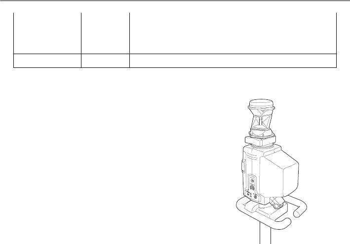
27. OPTIONAL ACCESSORIES
158
●On-demand Remote Control System (RC-PR3)
This system points the SRX in the direction of the
prism with speed and precision.
On-demand Remote Control System
Explanations
DOS/V DOC 27
D-Sub connector:
DOC 26 : 25 pins (female)
DOC 27 : 9 pins (male)
Other computers DOC1 No connector for attachment to a computer

159
28.SPECIFICATIONS
Except where stated, the following specifications apply to all SRXs.
Telescope
Length: 173mm
Aperture: 45mm (EDM/Auto Tracking:48mm)
Magnification 30X
Image: Erect
Resolving power 2.5"
Field of view 1°30' (26m/1,000m)
Minimum focus: 1.3m
Focussing screw: 1 speed
Reticle illumination: 5 brightness levels
Angle measurement
Horizontal and Vertical circles type:
Photoelectronical absolute encoder scanning
IACS (Independent Angle Calibration System)
SRX1/SRX2 only
Vertical axis single
Angle units: Degree/Gon/Mil (selectable)
Minimum display: SRX1/SRX2: 0.5"/1" (selectable)
SRX3: 1"/5" (selectable)
SRX5: 5"/10" (selectable)
Display range 0°00’00" to 359°59’59.5"
Display interval Less than 0.3 sec (When "Minimum display" is set to 1"), less than 0.5
sec (When "Minimum display" is set to 0.5")
Accuracy:
SRX1: 1"
SRX2: 2"
SRX3: 3"
SRX5: 5"
(ISO 17123-3 : 2001)
Collimation compensation: On/Off (selectable)
Measuring mode:
Horizontal angle: Right/Left (selectable)
Vertical angle: Zenith/Horizontal/Horizontal ±90°/% (selectable)
Angle measurement settings
Horizontal angle: 0 SET, H.ANG
Manual indexing
Vertical circle Yes
Tilt angle compensation
Type: Liquid 2-axis tilt sensor
Range of compensation ±3
Accuracy SRX1: within ±3’: 3"
SRX2: within ±3’: 6"
SRX3: within ±3’: 10"
SRX5: within ±3’: 10"
Automatic compensator ON (V & H/V)/OFF (selectable)
Compensation constant Can be changed

28. SPECIFICATIONS
160
'Distance measurement
Measuring method: Coaxial phase-contrast measuring system
Signal source: Red laser diode 690nm
Class 3R
(IEC60825-1 Amd. 2: 2001/FDA CDRH 21CFR Part1040.10 and
1040.11 (Complies with FDA performance standards for laser
products except for deviations pursuant to Laser Notice No.50, dated
July 26, 2001.))
(When the prism or reflective sheet is selected in Config mode as
target, the output is equivalent to Class 1).
Measuring range: (Using Sokkia's reflective prism/reflective sheet target during normal
atmospheric conditions *1/ *2 is good atmospheric conditions)
Reflective sheet RS90N-K*3 1.3 to 500 m
360° Prism ATP1 1.3 to 1,000m
Standard prism AP01AR X 1 1.3 to 5,000 m
Standard prism AP01AR X 3 to 8,000 m (to 10,000 m)
Mini pole prism OR1PA 1.3 to 500 m
Compact prism CP01 1.3 to 2,500 m
Reflectorless (White)*4 0.3 to 500m
Reflectorless (Gray)*5 0.3 to 250m
Minimum display
Fine measurement
: SRX1/SRX2: 0.0001/0.001 m (selectable)
SRX3/SRX5: 0.001 m
Rapid measurement: 0.001 m
Tracking measurement: 0.01 m
Auto Tracking measurement:
0.01 m
Maximum slope distance: 19,200.0000 m
Distance unit: m/ft/US ft/inch (selectable)
Accuracy:
(Using prism)
Fine measurement SRX1: (1.5 + 2 ppm X D) mm (however, distance is more than 4 m
when using CPS12)
SRX2/SRX3/SRX5: (2 + 2ppm X D) mm
Rapid measurement (5 + 2 ppm X D) mm
(Using reflective sheet target)*3
Fine measurement: (3 + 2 ppm X D) mm
Rapid measurement (single) (6 + 2 ppm X D) mm
(Reflectorless (White))*4
Fine measurement
(3 + 2 ppm X D) mm (0.3 to 200m)
(5 + 10 ppm X D) mm (200 to 350m)
(10 + 10 ppm X D) mm (350 to 500m)
Rapid measurement (single):
(6 + 2 ppm X D) mm (0.3 to 200m)
(8 + 10 ppm X D) mm (200 to 350m)
(15 + 10 ppm X D) mm (350 to 500m)
(Reflectorless (Gray))
*5
Fine measurement:
(3 + 2ppm X D) mm (0.3 to 100m)

161
28. SPECIFICATIONS
(5 + 10ppm X D) mm (100 to 170m)
(10 + 10ppm X D) mm (170 to 250m)
Rapid measurement:
(6 + 2ppm X D) mm (0.3 to 100m)
(8 + 10ppm X D) mm (100 to 170m)
(15 + 10ppm X D) mm (170 to 250m)
(D: measurement distance; Unit: mm)
Measurement mode: Fine measurement (single/repeat)/Rapid measurement (single/
repeat)/Tracking (selectable)
Measuring time (fastest time under good atmospheric conditions, no compensation, EDM ALC at
appropriate setting, slope distance):
Fine measurement less than 1.6 sec + every 0.9 sec or less
Rapid measurement less than 1.3 sec + every 0.6 sec or less
Tracking measurement less than 1.3 sec + every 0.4 sec or less
Atmospheric correction Temperature, pressure, humidity input/ppm input (selectable):
Temperature input range:- 30 to 60°C (in 0.1°C step)
Pressure input range: 500 to 1,400 hPa (in 1hPa step)
375 to 1,050 mmHg (in 1mmHg step)
14.8 to 41.3 inchHg (in 0.1inchHg step)
Humidity input range: 0 to 100% (in 1% step)
ppm input range: -499 to 499 ppm (in 1 ppm step)
Prism constant correction: -99 to 99 mm (in 1 mm step)
0mm fixed for reflectorless measurement
Earth curvature and refraction correction:
No/Yes K=0.14/Yes K=0.20 (selectable)
Scale factor setting: 0.5 to 2.0
Sea level correction: No/Yes (selectable)
*1: Slight haze, visibility about 20 km, sunny periods, weak scintillation.
*2: No haze, visibility about 40 km, overcast, no scintillation.
*3: Figures when the laser beam strikes within 30° of the reflective sheet target.
*4: Figures when using Kodak Gray Card White side (reflection factor 90%).
*5: Figures when using Kodak Gray Card Gray side (reflection factor 18%).
Auto Tracking / Auto Pointing
Measuring method Pulse laser transmitter and CCD detector with co-axial optics
Signal source (emittted beam)infrared laser diode (830nm)
Class 1
(IEC60825-1 Amd. 2: 2001/FDA CDRH 21 CFR Part 1040.10 and
1040.11 (Complies with FDA performance standards for laser
products except for deviations pursuant to Laser Notice No.50, dated
July 26, 2001.))
Divergence angle: 2.1°
Viewing angle: ± 45’
Measuring range:
H: 360° (full transit)
V: Elevation angle 70°, Depression angle 40°
Maximum Auto Tracking measurement range:
360° Prism ATP1: 500m
Mini pole prism OR1PA: 400 m
Compact prism CP01: 600 m

28. SPECIFICATIONS
162
Standard prism AP01 800 m
Auto Tracking speed 14°/sec
(Prism moving at 5m/sec. at 20m distance)
Auto Pointing measurement range:
360° Prism ATP1: 600m
Mini pole prism OR1PA: 500 m
Compact prism CP01: 700 m
Standard prism AP01 1,000 m
Reflective sheet*6*7 RS90N-K
50m
Minimum Auto Pointing measurement range:
Mini pole prism OR1PA/Compact prism CP01:
1.3 m
Standard prism AP01/360° Prism ATP1:
2 m
Reflective sheet*7 RS90N-K5 m
Time to completed Auto Pointing (When prism/reflective sheet is in field-of-view)
Prism: less than 7 seconds
Reflective sheet*6*7: less than 7 seconds
Sighting accuracy (Standard deviation (1 σ) at 100m):
Prism: less than 3"
Reflective sheet*7 RT90C-K: less than 3mm
*6: When using a reflective sheet for Auto Pointing, the size of sheet (10 to 90 mm) must be
selected to correspond to the distance being measured
*7: Figures when the Auto Pointing beam strikes within 30° of the reflective sheet target.
Motor
Type DC motor drive with self-locking free rotation system
Motion range 360°(Vertical and horizontal)
Rotation speed 45°/sec (at 25°C)
(Rotating time: Less than 10 sec. (when rotating 180°, tilt
compensation off, at 25°C))
Fine motion Variable speed jogging knobs
Accuracy after rotation stopped± 5" (tilt compensation off, no vibration, wind, or influence of other
external factors)
Motor lifetime 1500 hours (at 25°C)
Overcurrent detection functionYes
Guide Light
(Slight haze, visibility about 20 km, sunny periods, weak scintillation)
Light source: LED (red 626 nm/green 524 nm)
(When SRX in Face 1 and guide light viewed from target side:
left = green, right = red, center = both)
Distance: 1.3 to 150m*1
Visible range:
Right and Left/Upward and Downward:
± 4° (7m/100m)
Resolving power at center area (width):
4’ (about 0.12/100m)
Brightness 3 levels (bright/normal/dim)

163
28. SPECIFICATIONS
Memory
Type Flash ROM
Capacity 64 Mbyte (Internal memory 1 Mbyte (minimum)
External memory
CF card (up to 1 Gbyte)
SD card (up to 1 Gbyte, requires CF adapter)
USB flash memory
Communications
Serial (RS-232C compatible) Combined communications and power supply connector
Bit rate: 1200*/2400/4800/9600/19200/38400 (selectable)
Data bits: 8 bits
Parity: No
Stop bit: 1 bit
Check sum Yes/No (selectable)
Xon/Xoff Yes/No (selectable)
USB USB Ver. 1.1, Host (Type A), Client (Type mini B)
Card slot Compact Flash Type II-compatible
Bluetooth wireless technology Yes (when RC-TS3 attached)
SFX Dial-Up function Yes
Serial port, Bluetooth connection (when RC-TS3 attached)
Handle (RC-TS3)
On-demand Remote Control System Beam Detector
Operable range (Slope distance when using RC-PR3)
Near mode 2*8 to 100 m*9 (normal atmospheric conditions*11)
2*8 to 150 m*9 (good atmospheric conditions*12)
Far mode 2*8 to 250 m*10 (normal atmospheric conditions*11)
2*8 to 300 m*9 (good atmospheric conditions*12)
Maximum detecting area (vertical angle)
-40° to +30° (on the basis of horizontal direction)
Optical lens protective cover Yes
*8: When there is almost no vertical interval between instrument height and the target height,
SRX instrument height is 1.5 m, target height is 0.10 m at a horizontal distance of 1.8 m
*9 When the vertical interval between SRX and the beam emitter of RC-PR3 is no more than 20m
*10: When the vertical interval between SRX and the beam emitter of RC-PR3 is no more than 40m
*11: Normal atmospheric conditions: Slight haze, visibility about 20 km, sunny periods, weak
scintillation.
*12: Good atmospheric conditions: No haze, visibility about 40 km, overcast, no scintillation.
On-demand Remote Control System (when RC-TS3 attached)
Turning operation time Less than 15 sec (until completion of rapid (single)measurement)
(When using RC-PR3 and CF-P1, Turning angle 90° to RC-PR3,
Auto Pointing mode set to Rapid)
Bluetooth wireless communication unit
BT Qualification ID B03489
Transmission method: FHSS (Bluetooth Specification Ver.1.2 compatible, TELEC-
compliant)
MTS_E_01.fm 163 ページ 2006年9月22日 金曜日 午前11時11分
28. SPECIFICATIONS
164
Bluetooth profile SPP, DUN
Frequency band: 2,402 to 2,48GHz
Modulation: GFSK (Gaussian frequency shift keying) 1 Mbps
Power class Class 1
Usable range 300m (When using SWT9)
(No obstacles, few vehicles or sources of radio emissions/
interference/electronic noise in the vicinity of the instrument, no rain)
Power Supply
Power source: Rechargeable Li-ion battery BDC58 (7.2V, 4.3Ah)
External power source Combined communications and power supply connector
Nominal voltage: 7.2 to 12V
Capacity: 25W
Working duration at 25 °C (after continuous Auto Tracking/rapid distance measurement (repeat)):
BDC58: about 2 hours
BDC46A: (optional accessory): about 30 mins
BDC60: (external battery, optional accessory): about 3.5 hours
BDC61 (external battery, optional accessory): about 7 hours
Backup battery Li-ion battery 3.0V (backs up clock and memory)
Lifetime: 5 years
Resume function Yes (For up to 1 minute following power OFF)
Battery state indicator 4 levels with message function
Auto power-off: 5 levels (5/10/15/30 min/Not set) (selectable)
Remote PWR-On function Yes (Via serial or Bluetooth connection (when RC-TS3 attached).
(Bluetooth: up to 30 min only))
Software
Operating system Windows CE Ver. 5.0
Application software SDR Level 5
General
Keys/Display
Display dimensions: 3.5 inch (8.9 cm) with active area of 72.5mm x 49.5mm
Display: Transflective TFT QVGA color LCD, 76,800 pixels (Horizontal X
Vertical: 320 X 240)
Backlight LED: 8 levels (selectable)
Brightness adjustment Automatic
Touch panel Resistance-sensitive analog type (polarizing filter + film + glass)
Keyboard 32 keys (power, edit, direct, cursor, numeric, soft function, operations,
power on, light)
Key backlight Yes
Trigger key Yes (right side)
Sensitivity of levels
Plate level: SRX1: 20"/2 mm
SRX2/SRX3/SRX5: 30"/2 mm
Electronic level
Graphic 3’
Digital ± 3’ 30"
Brightness: same as tilt angle compensation
Minimum display: same as setting for angle measurement
MTS_E_01.fm 164 ページ 2006年9月22日 金曜日 午前11時11分
165
28. SPECIFICATIONS
Circular level: 10'/2 mm
Target selection/registration
Target type selection Prism/pinpole prism/360° Prism/reflective sheet/reflectorless
(Factory setting: prism (prism constant: -30mm, aperture: 70mm)
Target registration Target type
Prism constant (Reflectorless: set to 0 mm)
Aperture (Not selectable for reflectorless)
Self-correction function Error message/code displayed when an error occurs
Calendar/clock function Yes
Laser-pointer function ON (Automatically switches OFF after 5 minutes)/OFF (selectable)
Laser radiation warning indicatorLCD, lit continuously while laser emitted
Dimensions/Weight
Instrument height: 236 mm from tribrach bottom
Size (with handle): 201 (W) X 220 (D) X 375 (H) mm (display on each face, RC-TS3
attached, excluding protruding sections)
201 (W) X 202 (D) X 375 (H) mm (display on face 1 only, handle
attached, excluding protruding sections)
Weight (with BDC58):
Display on both sides: 7.9kg
Display on one side: 7.7kg
Tribrach: WA100A
Operating environment
Operating temperature -20 to 50°C (no condensation)
Storage temperature range -30 to 70°C (no condensation)
Dust and water resistance IP64 (IEC 60529:2001)
MTS_E_01.fm 165 ページ 2006年9月22日 金曜日 午前11時11分
166
29.REGULATIONS
Radio Frequency Interference
WARNING: Changes or modifications to this unit not expressly approved by the party responsible for
compliance could void the user's authority to operate the equipment.
NOTE: This equipment has been tested and found to comply with the limits for a Class A digital device
pursuant to Part 15 of the FCC Rules. These limits are designed to provide reasonable protection
against harmful inter-ference when the equipment is operated in a commercial environment. This
equipment generates, uses, and can radiate radio frequency energy and, if not installed and used in
accordance with the instruction manual, may cause harmful interference to radio communications.
Operation of this equipment in a residential area is likely to cause harmful interference in which case
the user will be required to correct the interference at his own expense.
This transmitter must not be co-located or operated in conjunction with any other antenna or
transmitter.
This equipment complies with FCC radiation exposure limits set forth for uncontrolled equipment and
meets the FCC radio frequency (RF) Exposure Guidelines in Supplement C to OET65. This equipment
has very low levels of RF energy that is deemed to comply without maximum permissive exposure
evaluation (MPE). But it is desirable that it should be installed and operated with at least 20cm and
more between the radiator and person’s body (excluding extremeties: hands, wrists, feet and ankles).
Notice for Canada
This Class A digital apparatus meets all requirements of Canadian Interference-Causing Equipment
Regulations.
Cet appareil numérique de la Class A respecte toutes les exigences du Règlement sur le matériel
brouilleur du Canada.
This class A digital apparatus complies with Canadian ICES-003.
Cet appareil numerique de la classe A est conforme a la norme NMB-003 du Canada.
Operation is subject to the following two conditions: (1) this device may not cause interference, and
(2) this device must accept any interference, including interference that may cause undesired
operation of this device.
This equipment complies with IC radiation exposure limits set forth for uncontrolled equipment and
meets RSS-102 of the IC radio frequency (RF) Exposure rules. This equipment has very low levels of
RF energy that is deemed to comply without maximum permissive exposure evaluation (MPE). But it
is desirable that it should be installed and operated with at least 20cm and more between the radiator
and person’s body (excluding extremeties: hands, wrists, feet and ankles).
MTS_E_01.fm 166 ページ 2006年9月22日 金曜日 午後6時39分

167
29. REGULATIONS
CE Conformity Declaration

29. REGULATIONS
168

169
29. REGULATIONS
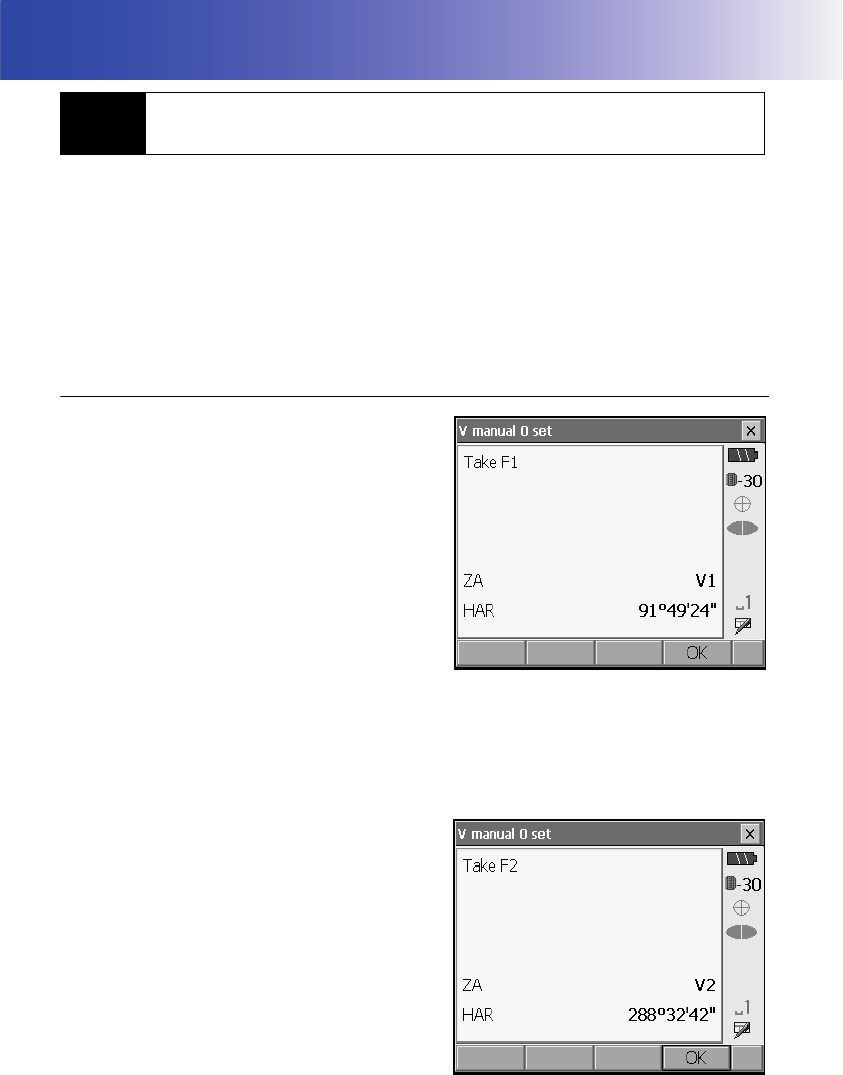
170
30.EXPLANATION
The 0 index of the vertical circle of your SRX is almost 100% accurate, but when it is necessary to
perform particularly high precision angle measurements, you can eliminate any inaccuracy of the 0
index as follows.
• If the power is cut off, the vertical circle indexing is ineffective. Do it again every time the power is
turned on.
• When indexing the vertical circle, sight the target manually.
PROCEDURE
1. Select “Obs.condition” in <Configuration>. Set “V
manual” (vertical circle indexing method) to “Yes”.
"21.1 Observation Conditions"
<V manual 0 set> is displayed.
2. Carefully level the instrument.
3. Accurately sight a clear target with a distance of
about 30m in the horizontal direction with the
telescope in face left.
Press [OK]. The SRX rotates 180°.
4. Accurately sight the same target and press [OK]
to rotate the SRX 180°. The vertical angle is
displayed.
This concludes the vertical circle indexing
procedure.
30.1 Manually Indexing the Vertical Circle by Face Left, Face
Right Measurement
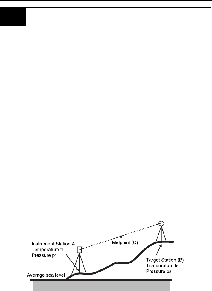
171
30. EXPLANATION
• Need for atmospheric correction
The SRX measures the distance with a beam of light, but the velocity of this light varies according
to the index of refraction of light in the atmosphere. This index of refraction varies according to the
temperature and pressure. Near normal temperature and pressure conditions:
With constant pressure, a temperature change of 1°: an index change of 1 ppm.
With constant temperature, a pressure change of 3.6 hPa: an index change of 1 ppm.
To perform high accuracy measurements, it is necessary to find the atmospheric correction factor
from even more accurate temperature and pressure measurements and perform an atmospheric
correction.
Sokkia recommends that extremely precise instruments be used to monitor the air temperature and
pressure.
• Finding the average temperature and pressure between two points in different atmospheric
conditions
To precisely determine the atmospheric correction factor, the average temperature and air pressure
along the measurement beam route must be taken.
Determine the temperature and pressure as follows.
Flat terrain :Use the temperature and pressure at the midpoint of the line.
Mountainous terrain :Use the temperature and pressure at the intermediate point (C).
If it is not possible to measure the temperature and pressure at the midpoint, take the temperature
and pressure at the instrument station (A) and the target station (B), then calculate the average
value.
Average air temperature :(t1 + t2)/2
Average air pressure :(p1 + p2)/2
• Calculation of atmospheric correction factor allowing for humidity
30.2 Atmospheric Correction for High Precision Distance
Measurement

30. EXPLANATION
172
The humidity has little influence, particularly on short distance measurements. The effect of humidity
should be considered in cases where it is very hot and humid and high precision measurements are
to be performed over a particularly long distance.
When taking humidity into consideration, enter the atmospheric correction factor calculated using
the following formula.
e (water vapor pressure) can be calculated using the following formula.
t : Air temperature (°C)
p : Pressure (hPa)
e : Water vapor pressure (hPa)
h : Relative humidity (%)
ew: Saturated water vapor pressure
282.324 0.294362 p×
1 0.003661 t×+
------------------------------------------
–
⎝
⎛0.04127 e×
1 0.003661 t×+
------------------------------------------ ⎠
⎞10 6–
×+
Atmospheric Correction Factor (ppm) =
ew 6.11 10
7.5 t×()
t 237.3+()
----------------------------
×=
eh
ew
100
----------
×=

177
31. INDEX
A
Accu. search.............................................52
Atmospheric correction factor.................122
Automatic tilt angle compensation mechanism 118
B
Bluetooth connections .............................36
Bluetooth Device Address........................36
C
Cold boot .................................................49
Collimation correction ............................118
D
Date and Time....................................... 134
E
EDM ALC ...............................................120
Eliminating parallax .................................55
G
Guide light ...............................................11
H
Horizontal angle settings ...................76, 83
I
Inch (Fraction of an inch)........................132
Instrument height mark ............................11
L
Laser-pointer function...............................11
Laser radiation warning indicator ............11
Lost prism.................................................58
P
Peep sight ...............................................11
Power-saving automatic cut-off/Backlight Off 120
Prism constant correction.......................121
Problems Powering OFF ..........................49
R
Resume function .....................................48
S
Slope area ..............................................112
Srch method .............................................52
T
Trigger key ..............................................11
V
Vertical and Horizontal jogging knobs ......11
V mode (vertical angle display method) .118

MEMO

JAPAN
1st ed. 01-0609 Printed in Japan ©2006 SOKKIA CO., LT
D