Sony 6220501-BV Transmitter module for mobile applications User Manual GM47 Integrators Manual
Sony Mobile Communications Inc Transmitter module for mobile applications GM47 Integrators Manual
Sony >
Contents
- 1. Exhibit 08 Manual
- 2. Exhibit 8 Design Guidelines
- 3. Exhibit 8 Integrators Manual
- 4. revised page
Exhibit 8 Integrators Manual

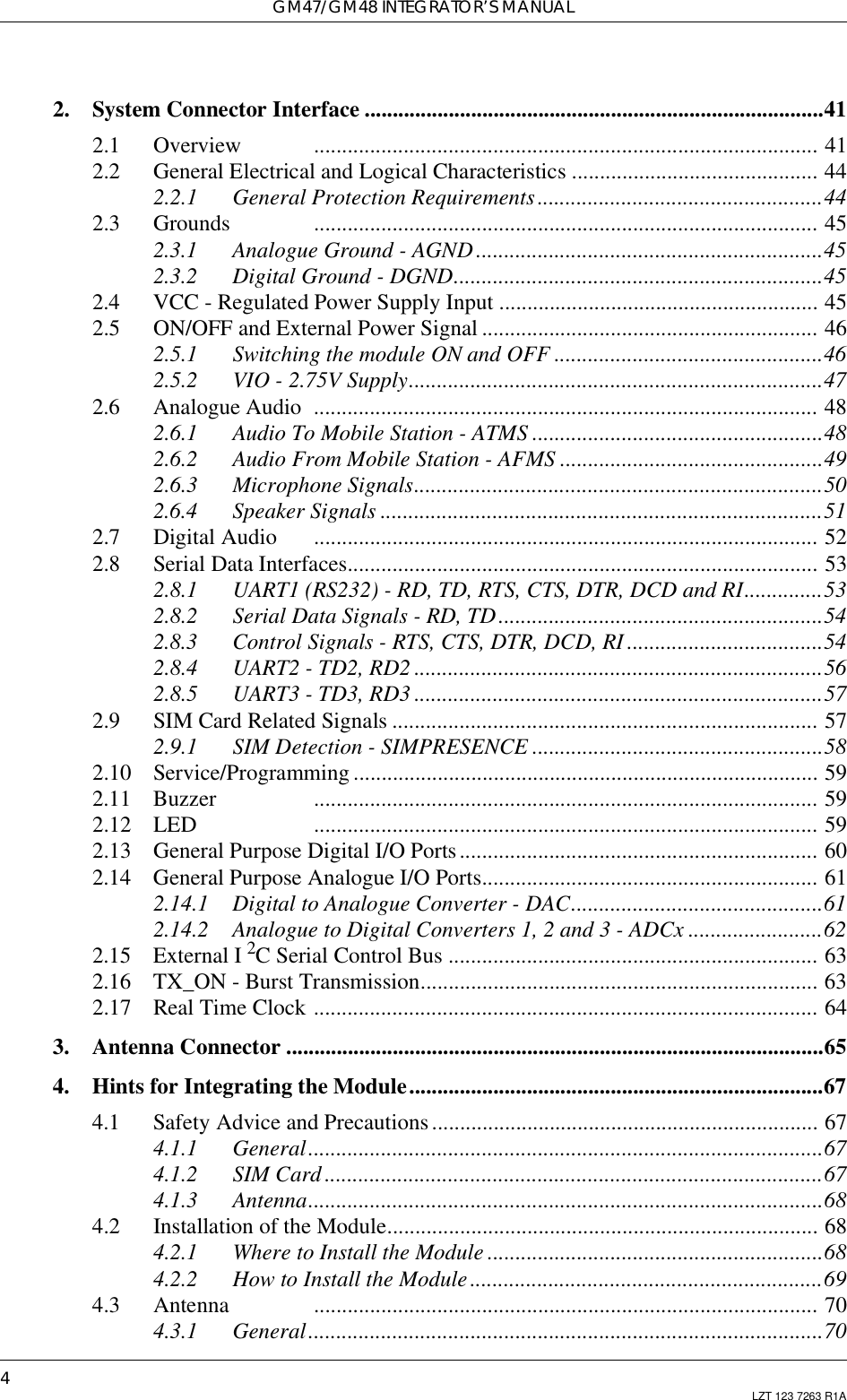

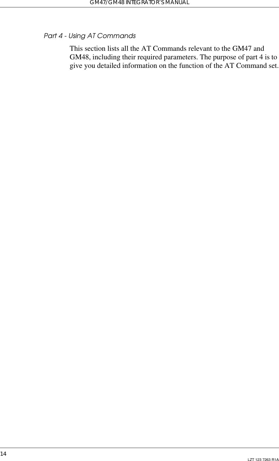
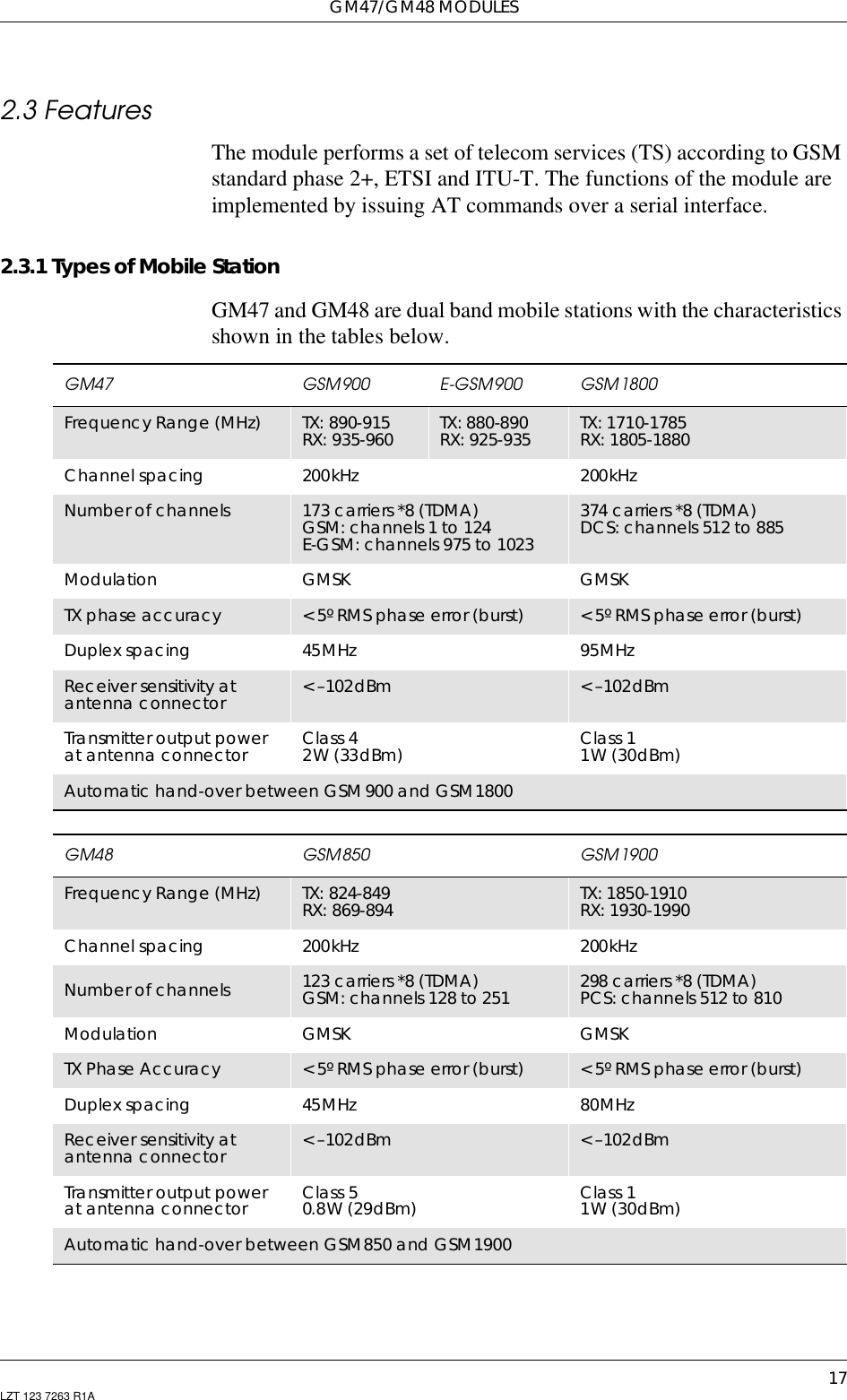


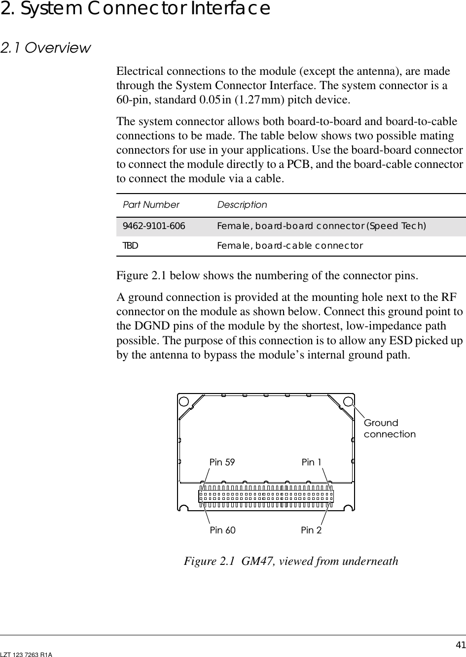

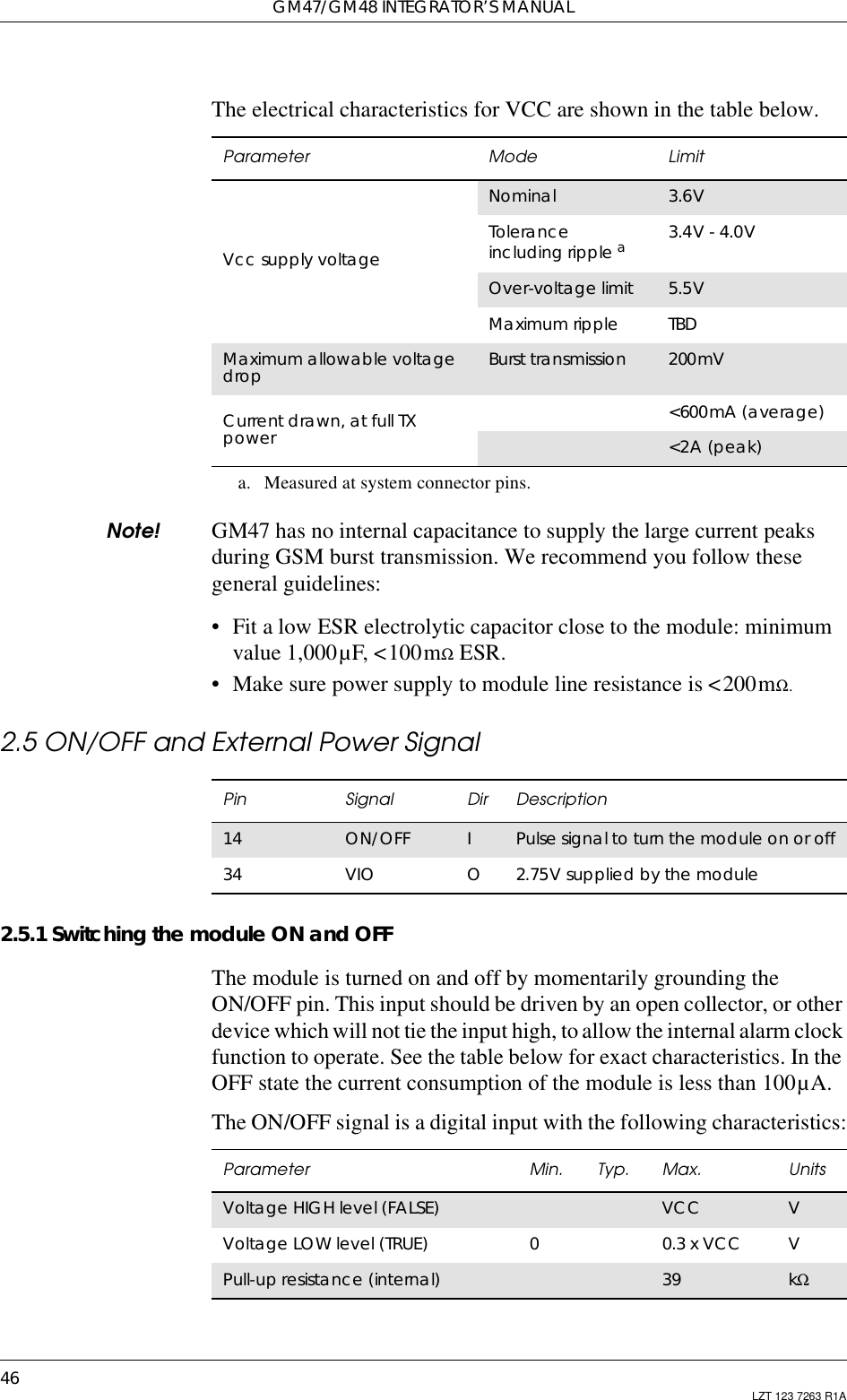
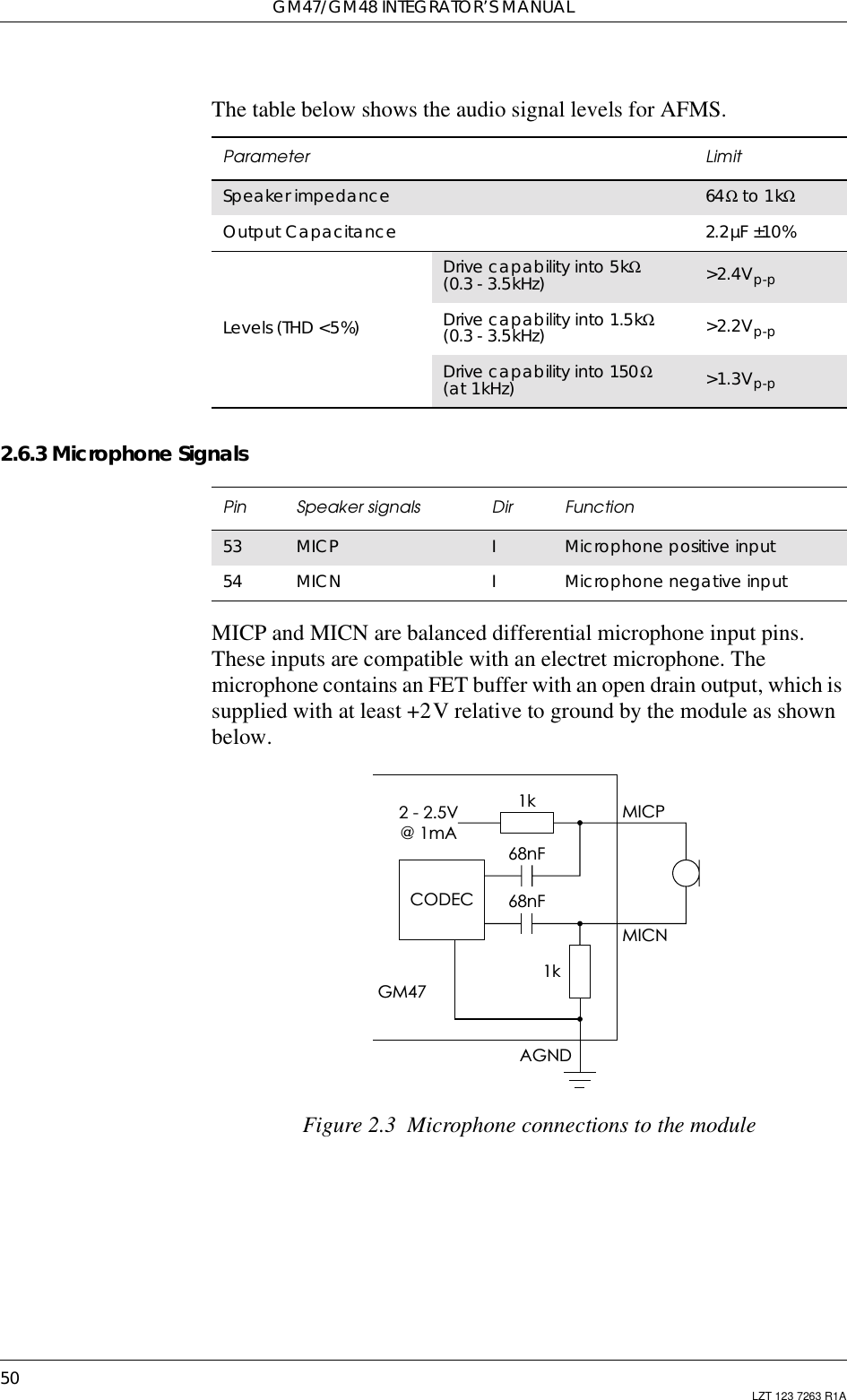
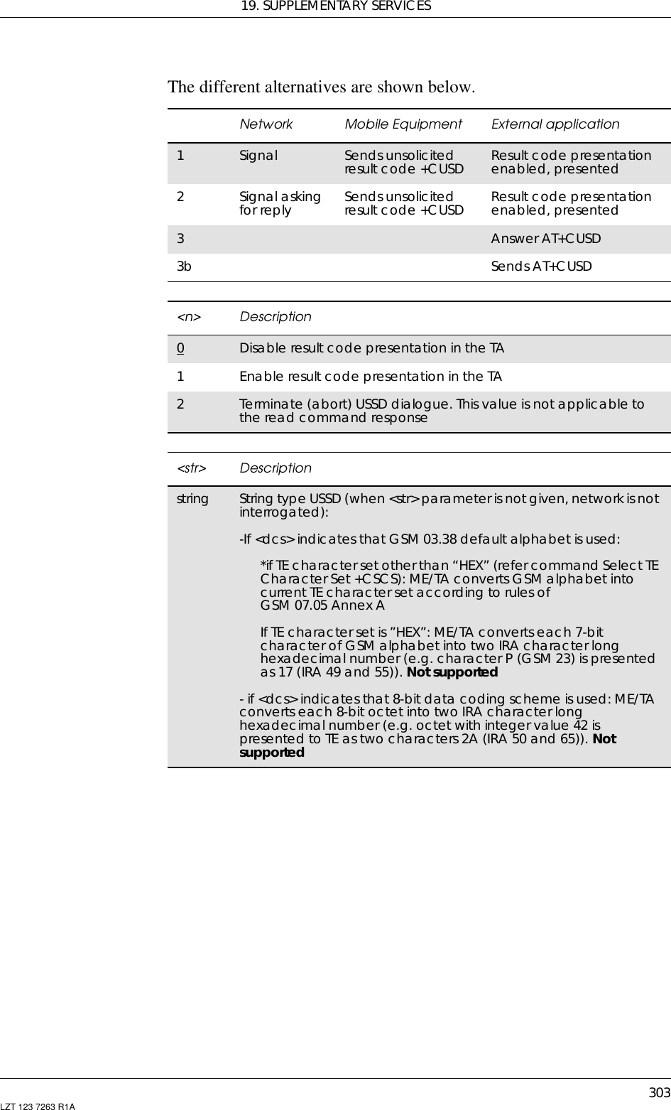
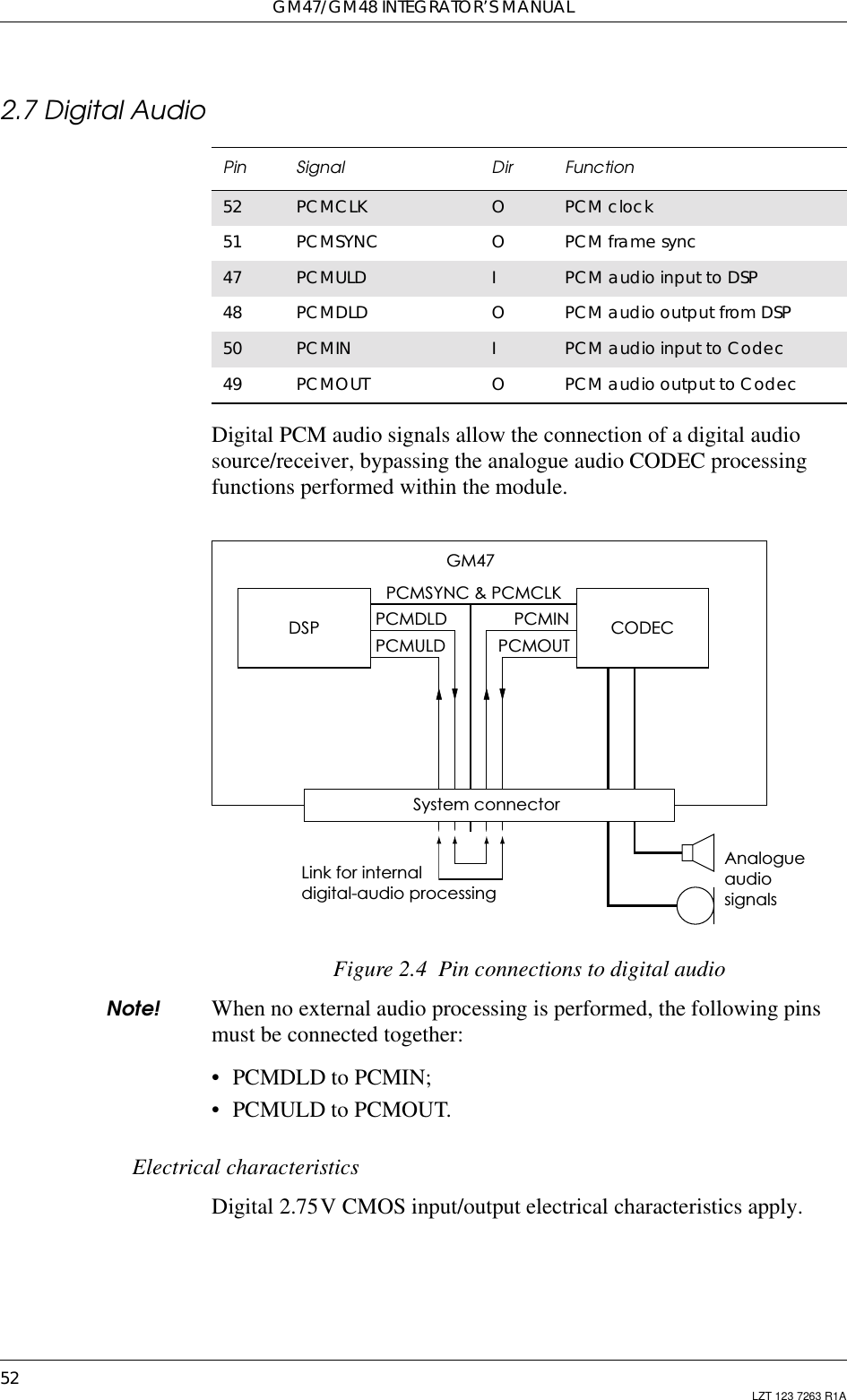
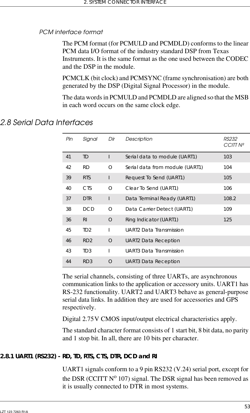
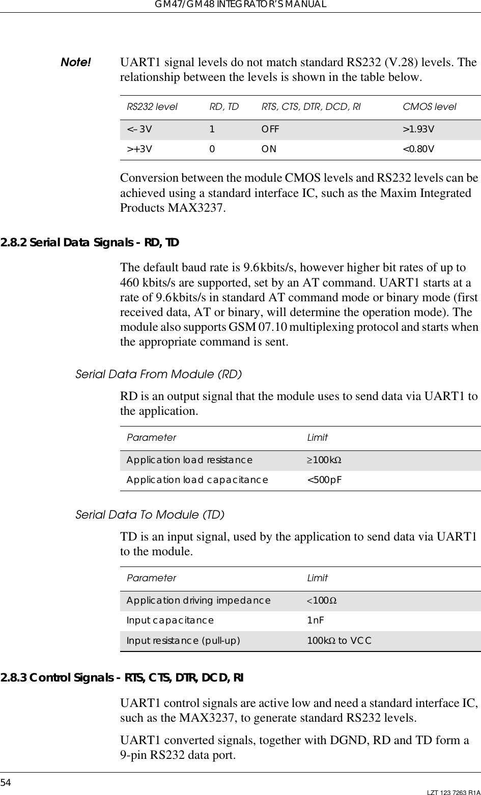
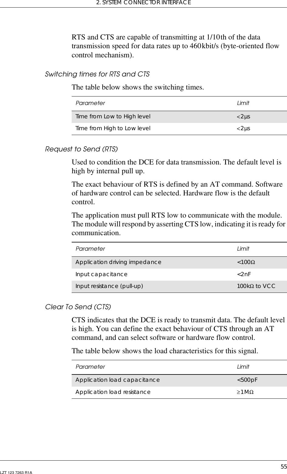
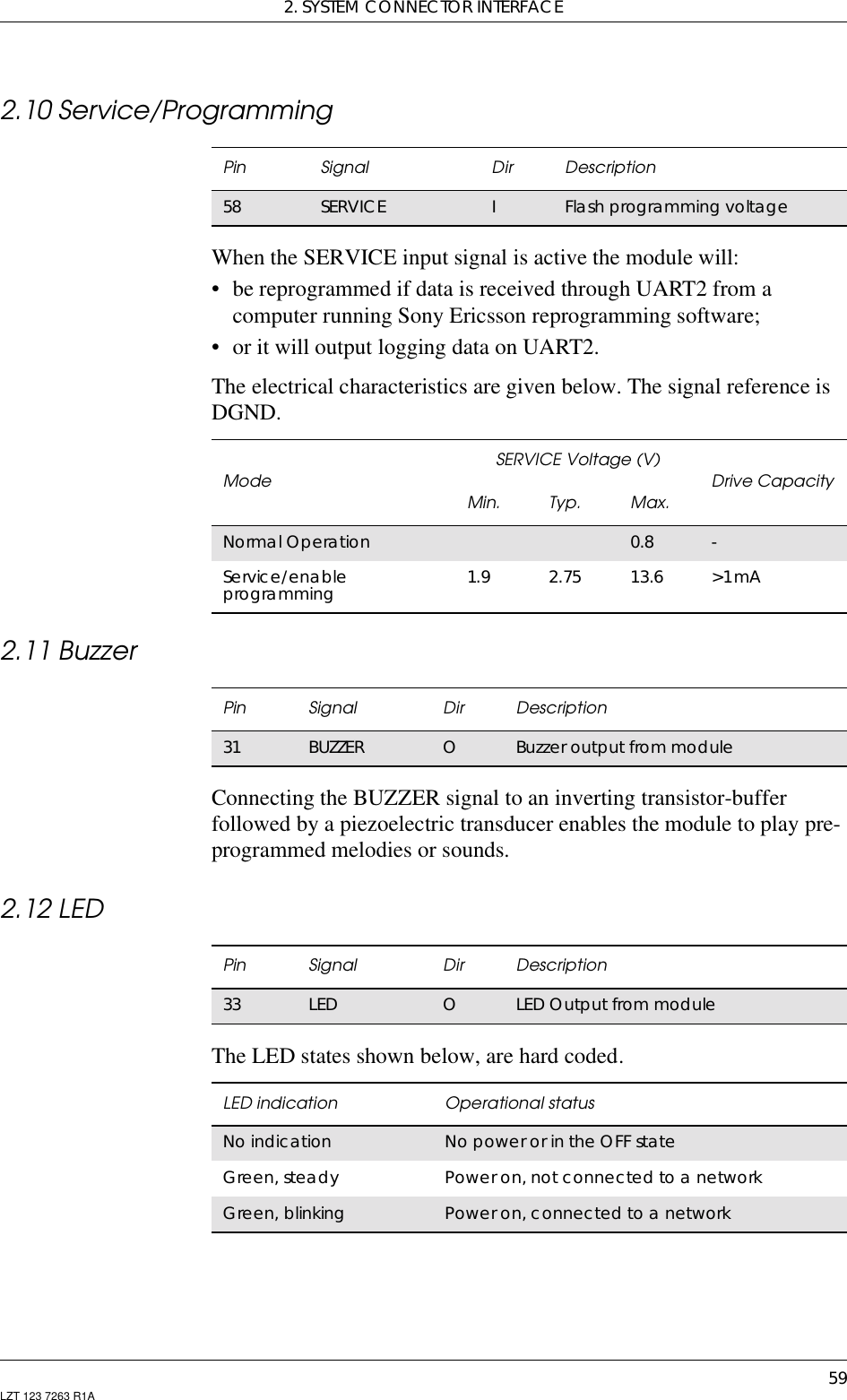
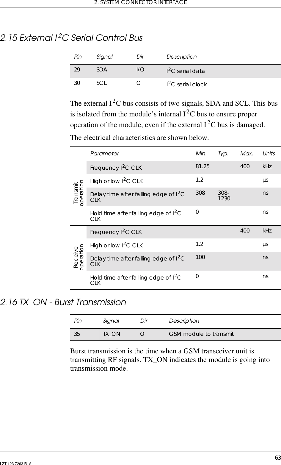
![2. SYSTEM CONNECTOR INTERFACE51LZT 123 7263 R1A2.6.4 Speaker SignalsBEARP and BEARN are the speaker output pins. These aredifferential-mode outputs. The electrical characteristics are given in thetable below.The following table shows the ear piece impedances that can beconnected to BEARP and BEARN.Pin Speaker signals Dir Function55 BEARP OSpeaker positive output56 BEARN OSpeaker negative outputParameter LimitOutput level (differential) ≥4.0VppOutput level (dynamic load = 32Ω)≥2.8VppGain PCMINato BEARP/BEARN (differential)a. See PCMIN signal in “2.7 Digital Audio”, page 52–9dB ±1Distortion at 1kHz and maximum output level ≤5%Offset, BEARP to BEARN ±30mVEar-piece mute-switch attenuation ≥40dBEar piece model Impedance ToleranceDynamic ear piece [32Ω + 800µH] // 100pF ±20%Dynamic ear piece [150Ω +800µH]//100pF ±20%Piezo ear piece 1kΩ +60nF ±20%](https://usermanual.wiki/Sony/6220501-BV.Exhibit-8-Integrators-Manual/User-Guide-247869-Page-51.png)
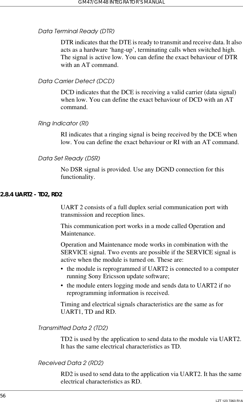

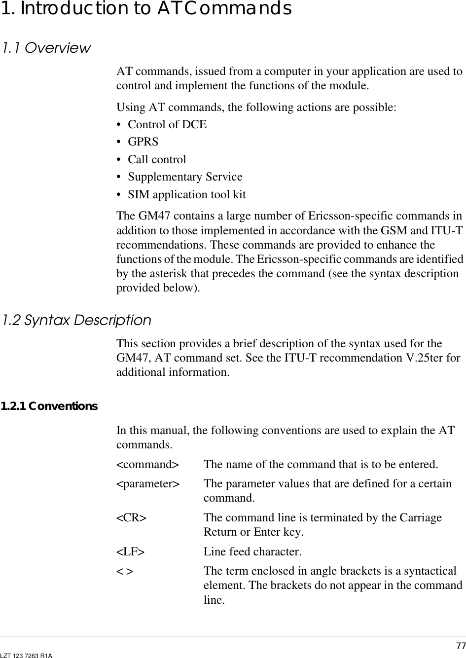
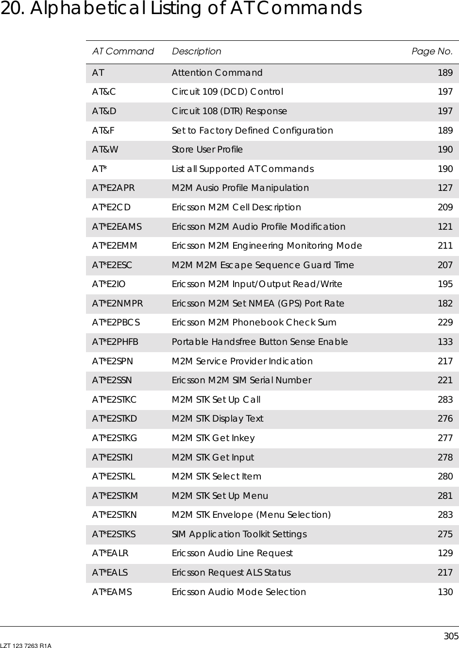
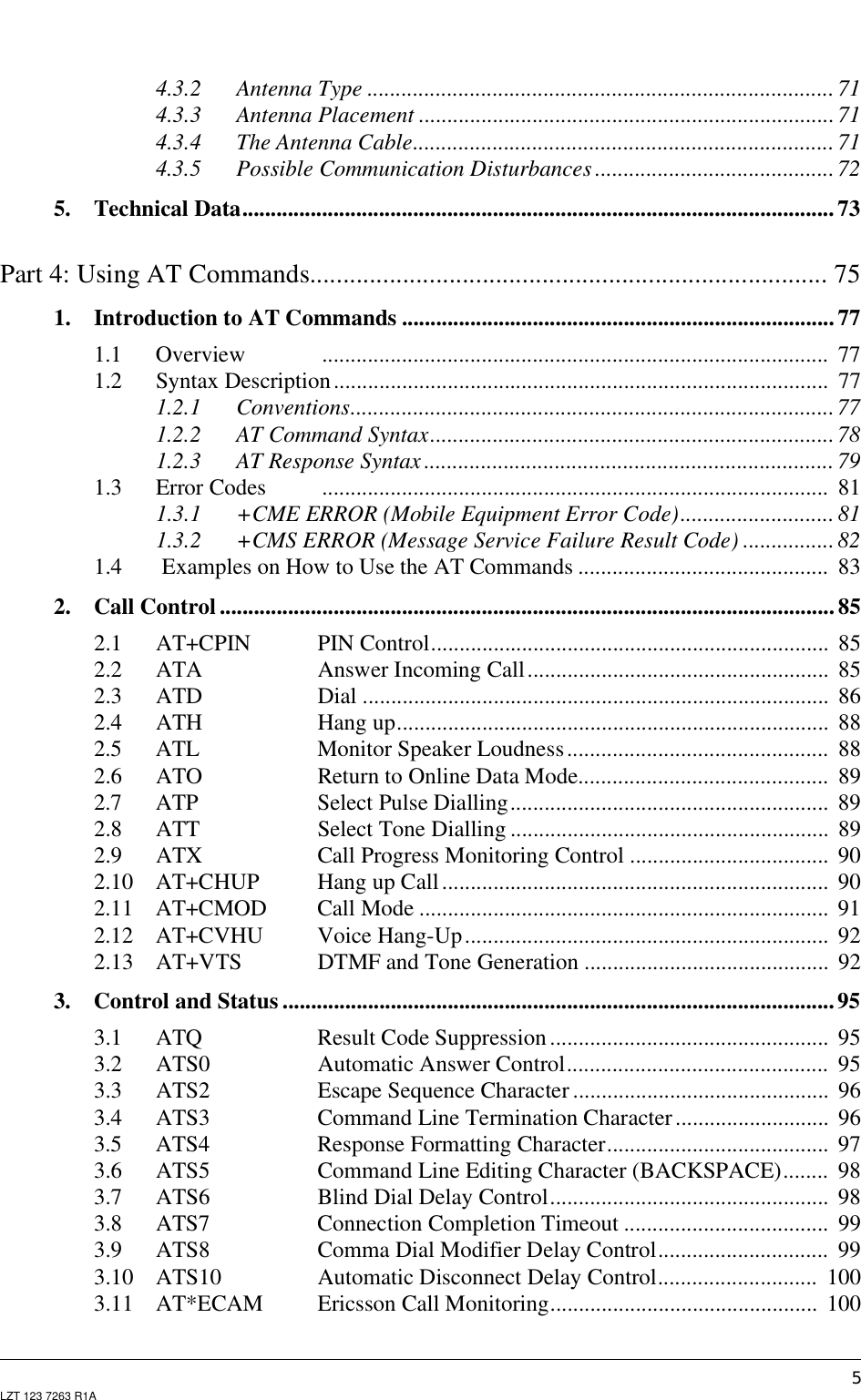
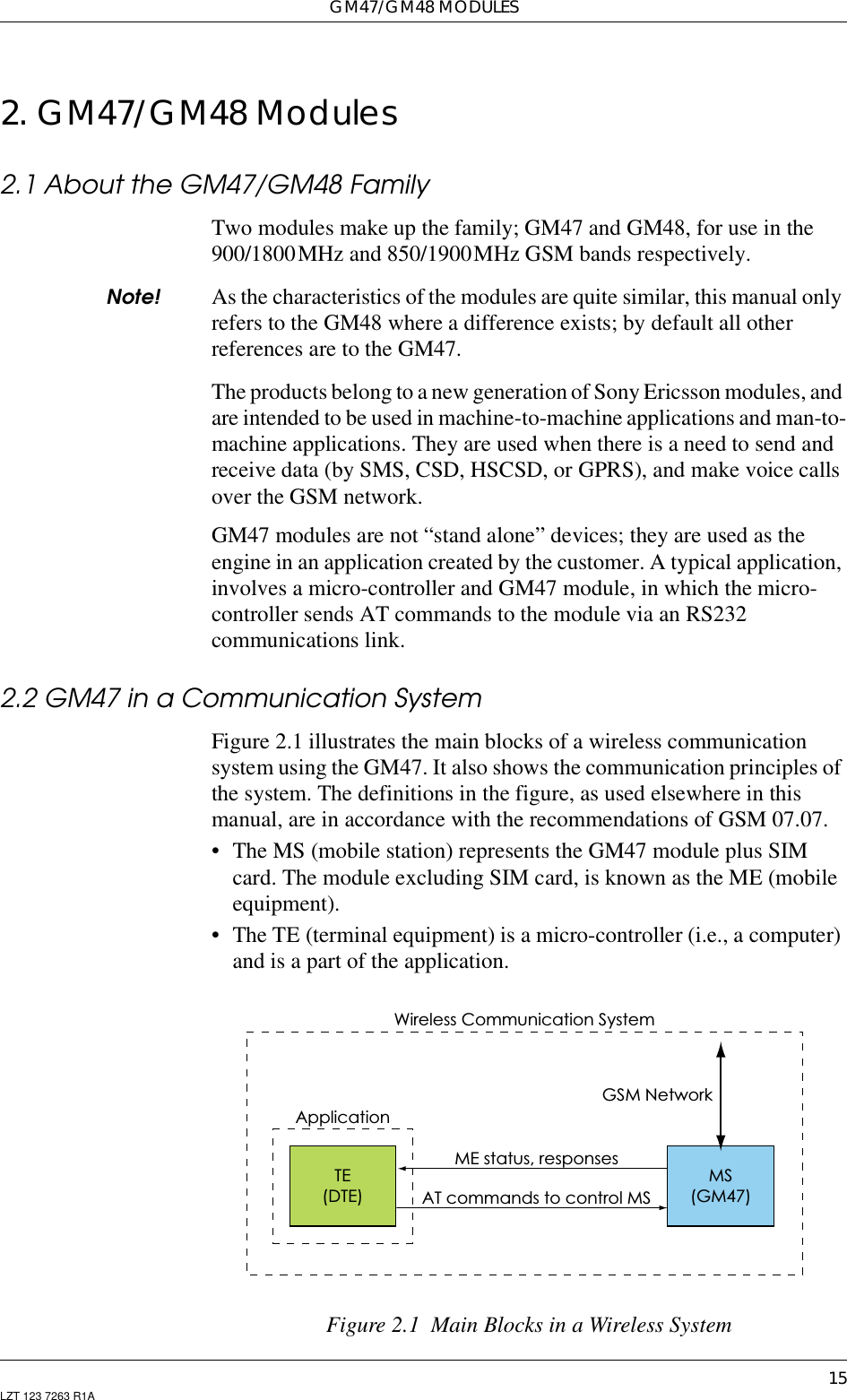
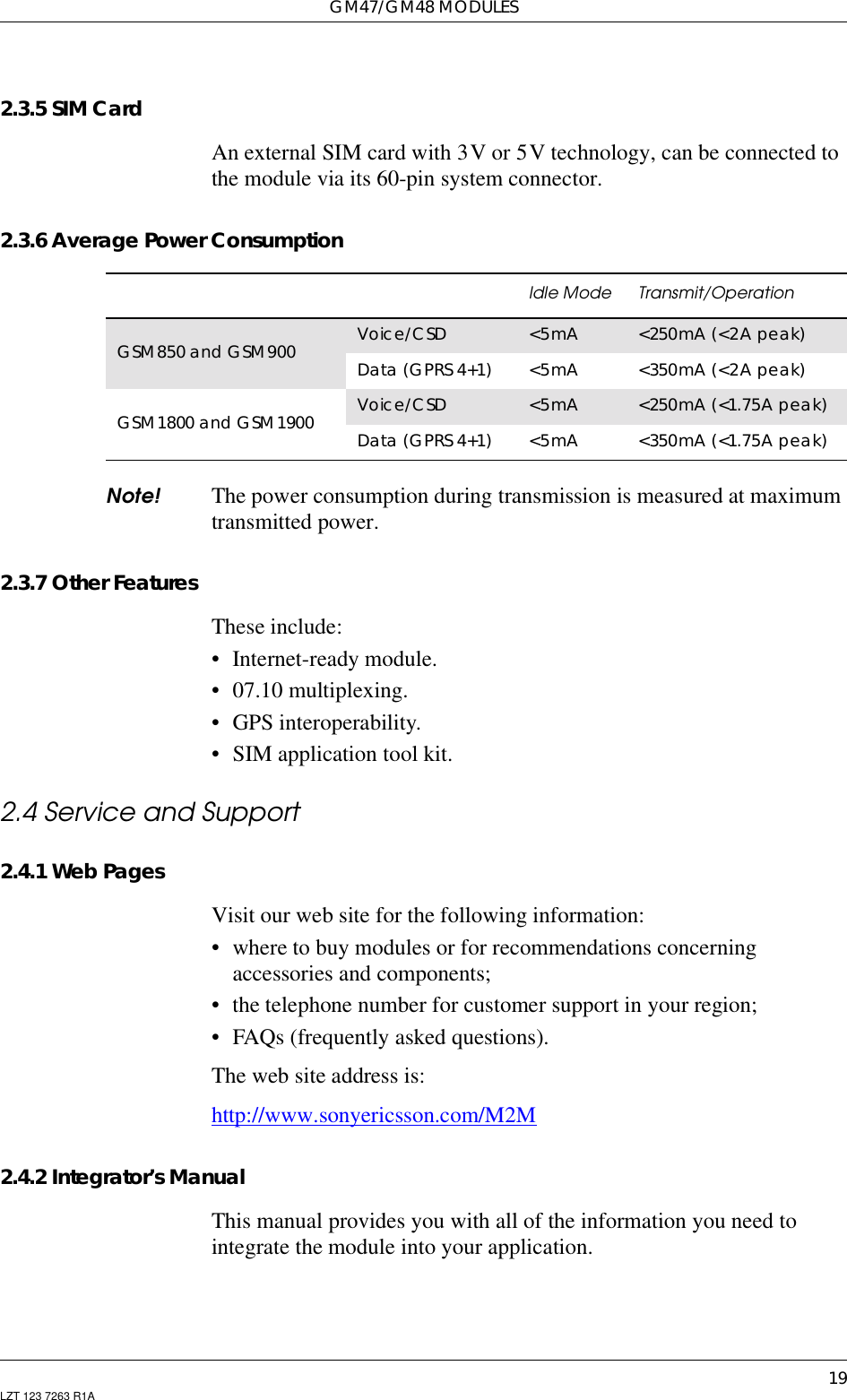
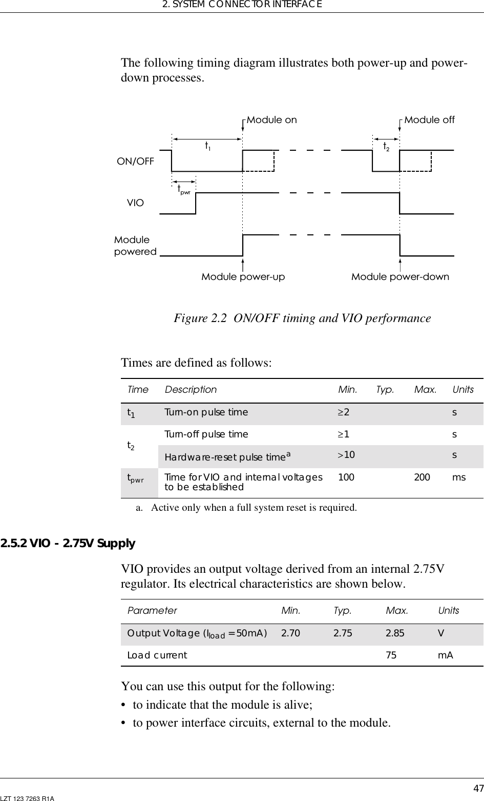
![GM47/GM48 INTEGRATOR’S MANUAL78 LZT 123 7263 R1A[ ] Square brackets are used to indicatethat a certainitemis optional. For example, sub-parameters of acommand or an optional part of a response. Thebrackets do not appear in the command line.Value The default values of the supported parameters areindicated by using bold text when presenting thevalue.• Other characters, including ‘?’, ‘=’, parenthesis, etc., appear incommands and responses as written.• The final result codes OK, ERROR, +CME ERROR: <err> andCMS ERROR:<err> (see sections 1.2.3, AT Response Syntax and1.3, Error Codes) are not listed under “Possible Responses” for eachAT command.• OK and ERROR are listed if these are the only possible responses.1.2.2 AT Command SyntaxThe AT standard is a line-oriented command language. Each commandis made up of the following three elements:• the prefix;• the body;• the termination character.The prefix consists of the letters “AT”, which are derived from the firsttwo letters of the word attention. The body is made up of the command,the parameter, and if applicable the associated values.Commands may be combined in the same command line. Spacesbetween the individual bodies are ignored.Basic Syntax CommandThe format of basic syntax commands is as follows:AT<command>[=][<parameter>]Example! ATL=0<CR> (sets the volume of the speaker)Additional commands may follow a command on the same commandline without any character being required for separation. For thecommand D parameters, see the description for the command inquestion.A version of the basic syntax is:AT<command><parameter>Extended Syntax Command• AT+<command>= [<parameter>]](https://usermanual.wiki/Sony/6220501-BV.Exhibit-8-Integrators-Manual/User-Guide-247869-Page-78.png)
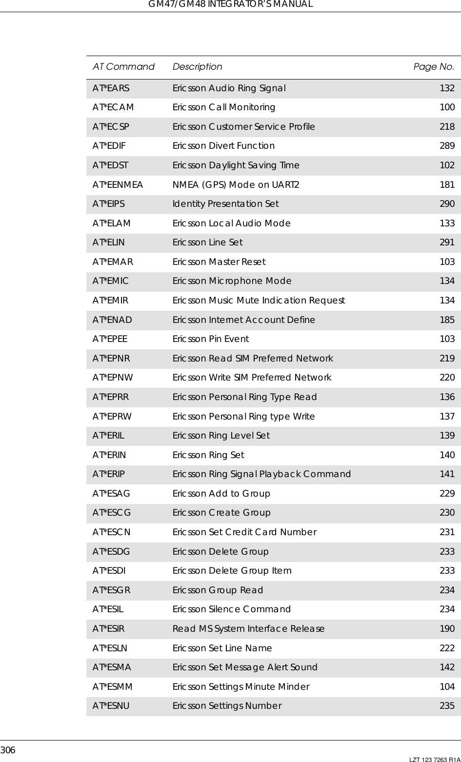
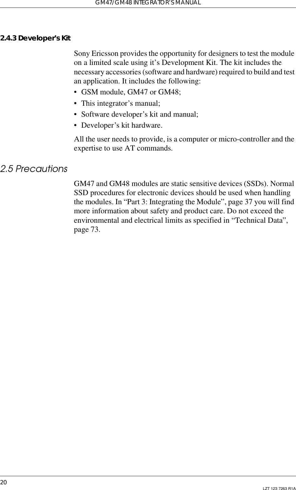
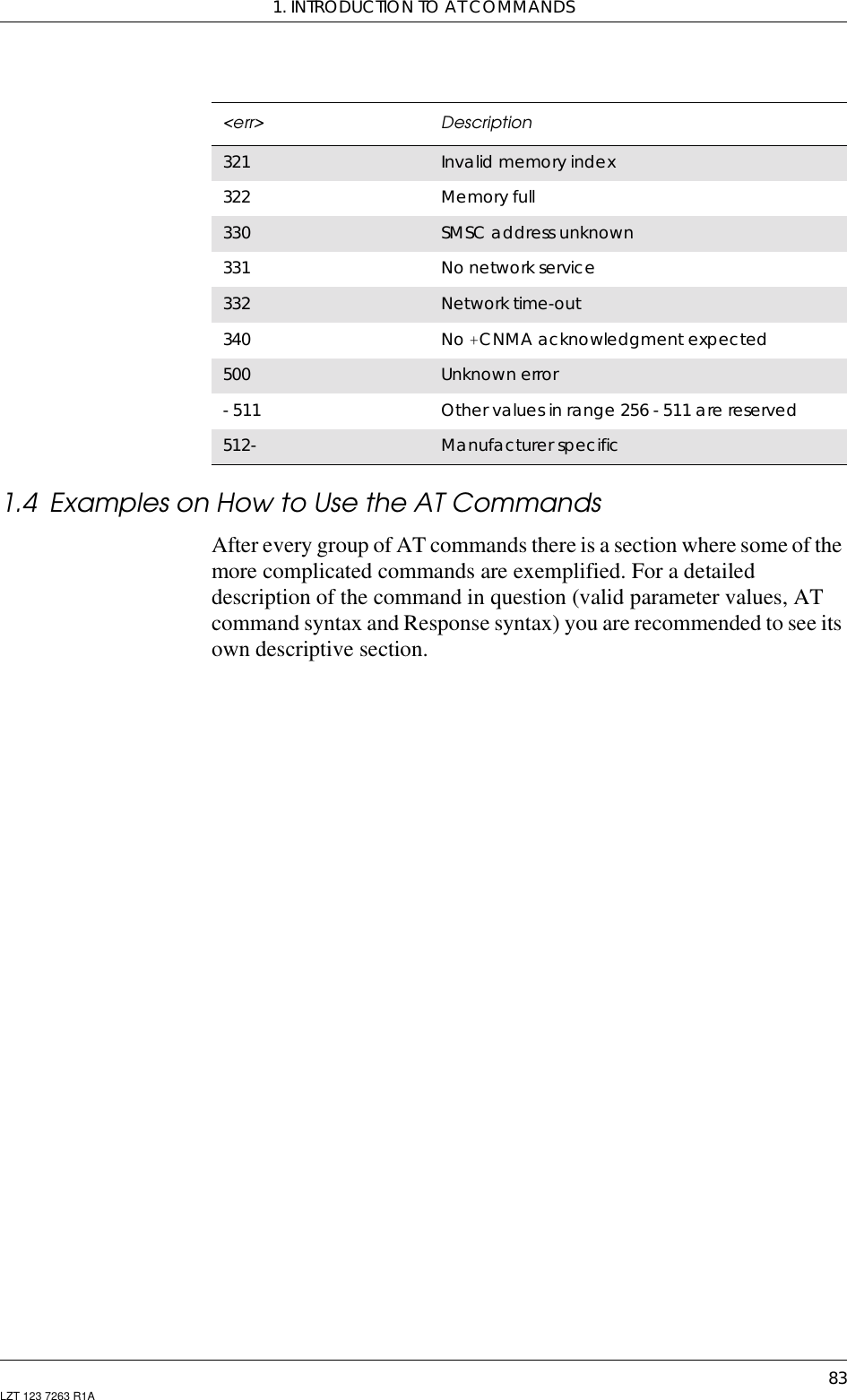
![1. INTRODUCTION TO AT COMMANDS79LZT 123 7263 R1A• AT*<command>=[<parameter>]Example! AT+CFUN=0<CR> (powers down the module)If several values are included in the command, they are separated bycommas. It is also possible to enter commands with no values.Additional commands may follow an extended syntax command on thesame command line if a semicolon (;IRA 3B) is inserted after thepreceeding extended command as a separator.Read Command SyntaxThe read command is used to check the current values ofparameters. Type ‘?’, after the command line:• AT+<command>?• AT*<command>?• AT<command>?Example! AT+CSCS?<CR> (show current character set)<CR>“IRA”<CR>(information text response)<CR>OK<CR>(final result code response)Test Command SyntaxThe test command is used to test whether the command has beenimplemented or to give information about the type of subparameters itcontains. Type ‘?’, after the command line:• AT+<command>=?• AT*<command>=?Example! AT+CPAS=?<CR> (shows supported values for the responseparameters)<CR>CPAS: (0, 3, 4, 129, 130, 131)<CR> (supported values)<CR>OK<CR> (final result code)If the indicated <parameter> is not recognized, the result code ERRORis issued.Note! Possible responses are indicated both as <command>:(list ofsupported<parameter>) and (in most cases) the actual range of theparameter values.1.2.3 AT Response SyntaxThe default mode response shown below, is in text mode. See thecommand V for further details.](https://usermanual.wiki/Sony/6220501-BV.Exhibit-8-Integrators-Manual/User-Guide-247869-Page-79.png)

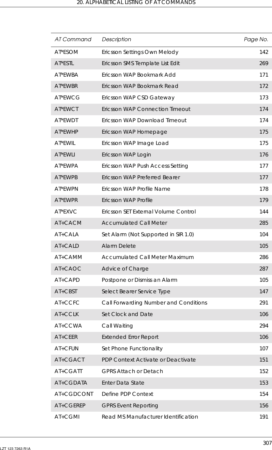
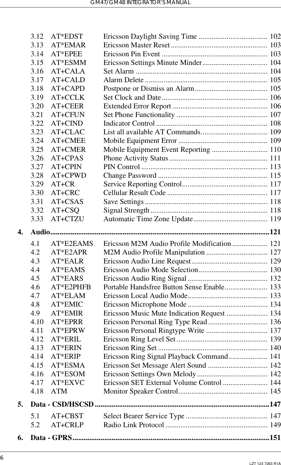
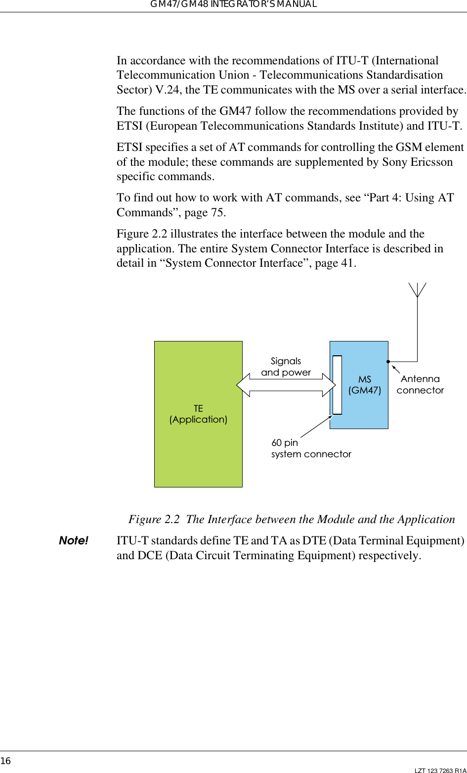
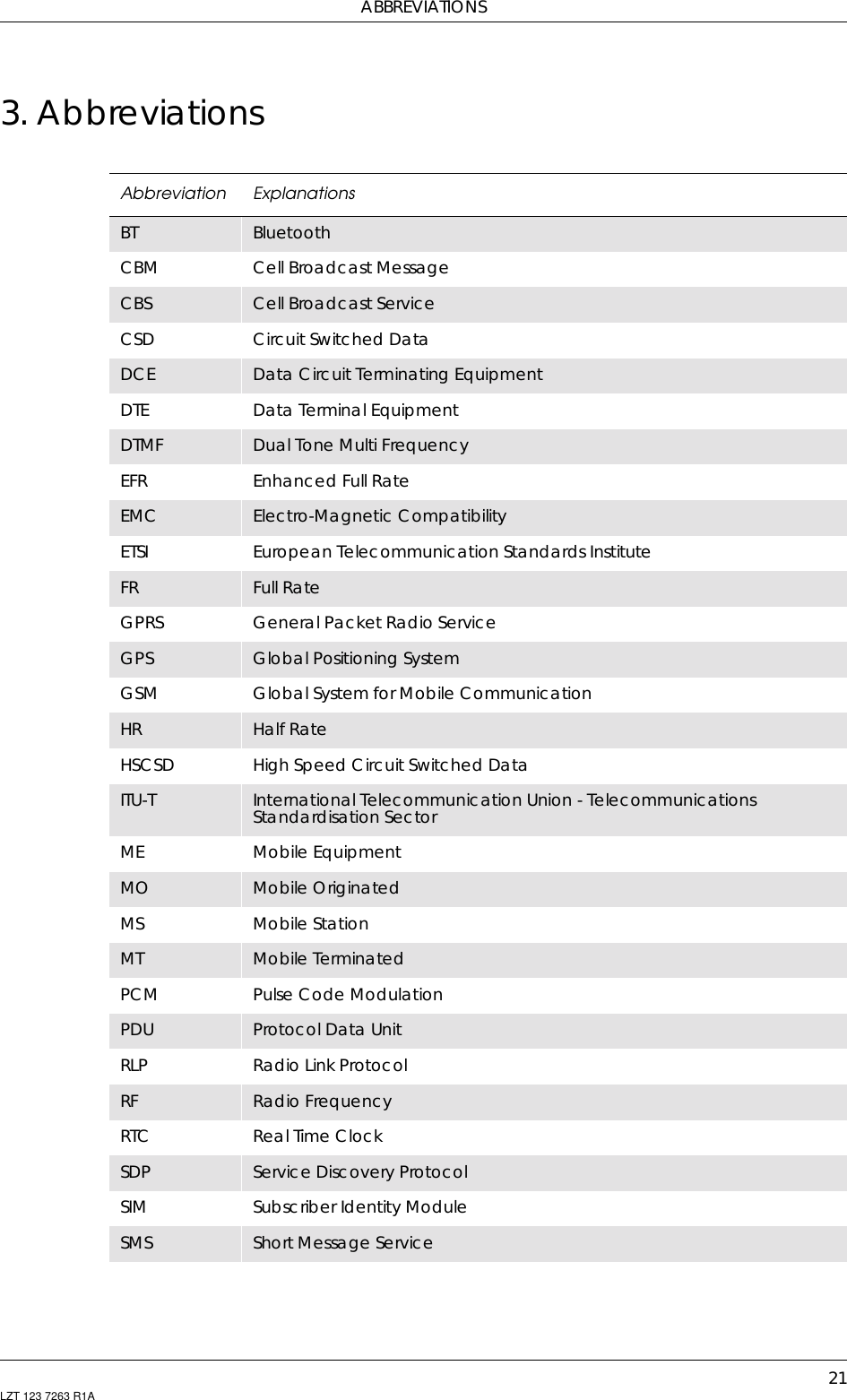
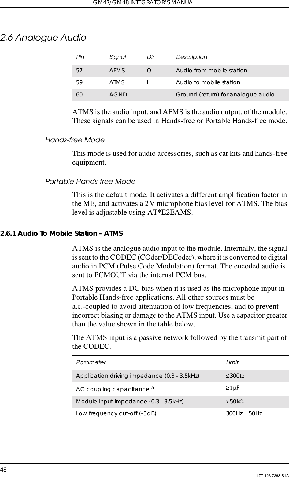
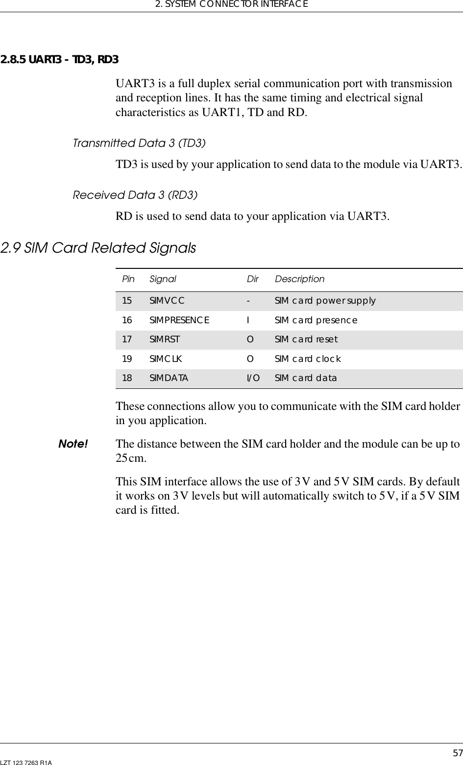
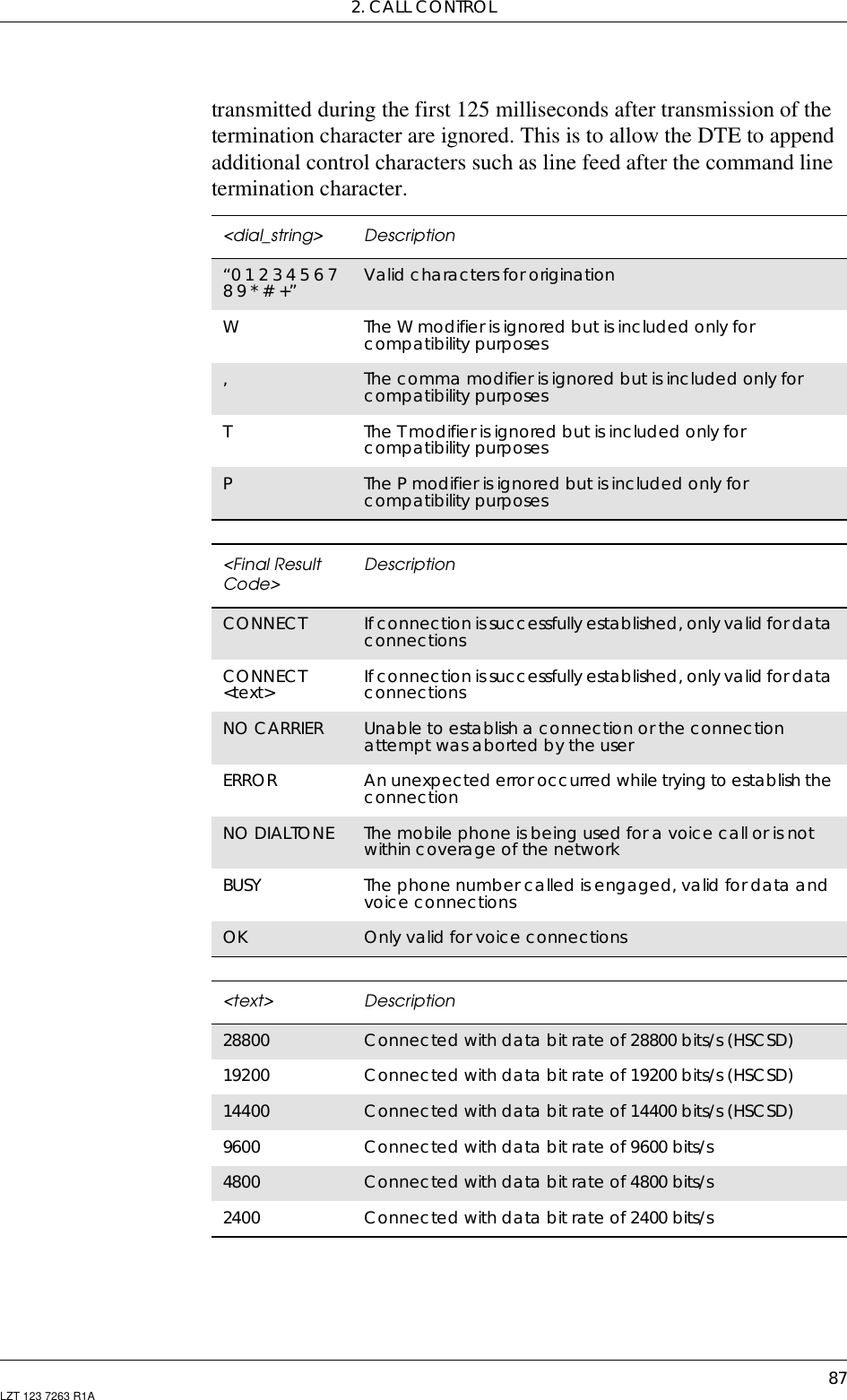
![GM47/GM48 INTEGRATOR’S MANUAL86 LZT 123 7263 R1A2.3 ATD DialUsed to initiate a phone connection, which may be data or voice (phonenumber terminated by semicolon). The phone number used to establishthe connection will consist of digits and modifiers, or a stored numberspecification.If the dial string is followed by a semicolon this informs the phone thatthe number is a voice rather than a data number.If the dial string is omitted, and the semicolon included, the commandinstructs the ME to do a network detect. If the network is available OKis returned.Abortability:Aborting an ATD command is accomplished by the transmission fromthe DTE to the DCE of any character. A single character shall besufficient to abort the command in progress; however, charactersDescription Syntax Possible Responses• Originate a call anddial the phonenumber specified inthe command as<dial_string>or•DoanetworkdetectATD<dial_string>[;] •CONNECT•CONNECT<text>• NO CARRIER•ERROR•NODIALTONE•BUSY•OKDial the phone numberstored in the mobilephone which islocated by the index<I>ATD>ME<I>[;] •CONNECT•CONNECT<text>• NO CARRIER•ERROR•NODIALTONE•BUSY•OKDial the phone numberstored in the SIM cardwhich is located by theindex <I>ATD>SM<I>[;] •CONNECT•CONNECT<text>• NO CARRIER•ERROR•NODIALTONE•BUSY•OKDial the phone numberstored in the Lastdialled number list onthe SIM card, which islocated by the index<I>The most recentlydialled number isassumed to have<I>="1"ATD>LD<I>[;] •CONNECT•CONNECT<text>• NO CARRIER•ERROR•NODIALTONE•BUSY•OKRedial the last phonenumber dialled.Ericsson specificATDL[;] ...](https://usermanual.wiki/Sony/6220501-BV.Exhibit-8-Integrators-Manual/User-Guide-247869-Page-86.png)
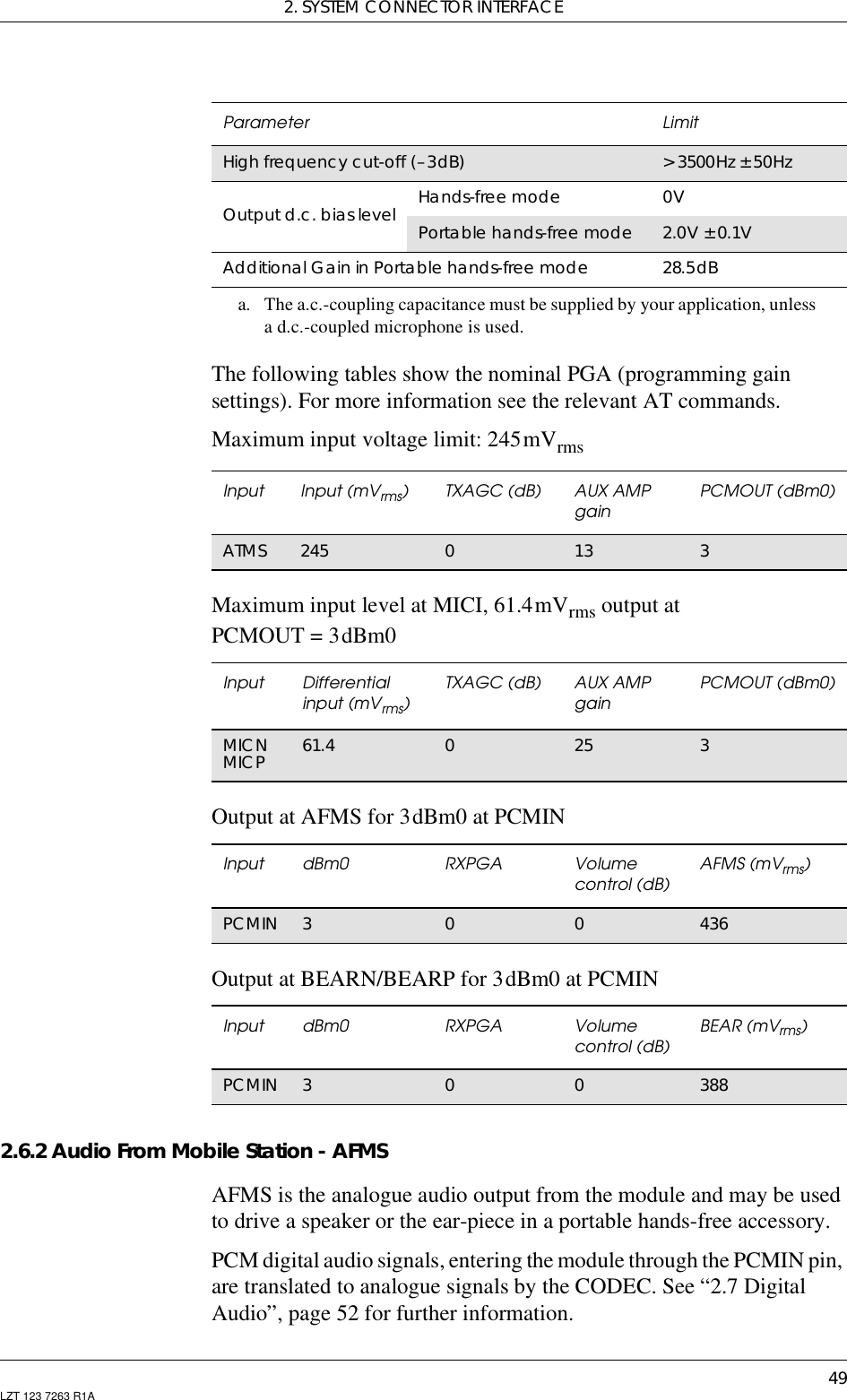
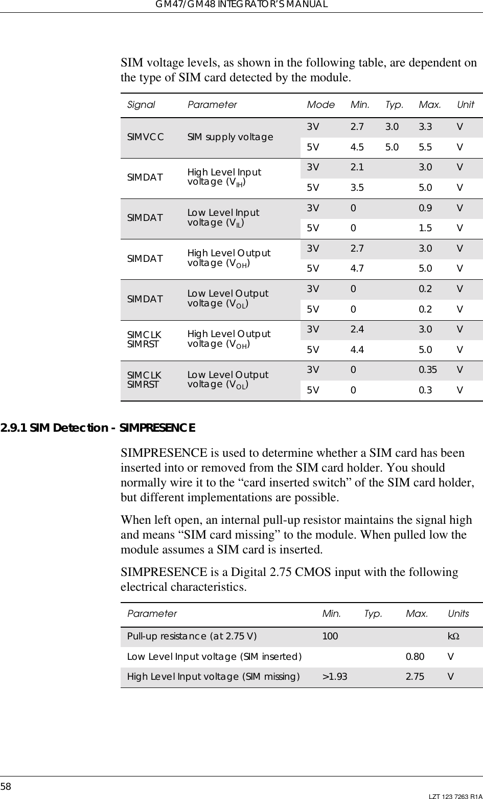
![GM47/GM48 INTEGRATOR’S MANUAL88 LZT 123 7263 R1A2.4 ATH Hang upSignals the MS to terminate an active call.2.5 ATL Monitor Speaker LoudnessControls the volume of the monitor speaker. The specific loudness levelindicated by “low”, “medium” and “high” is manufacturer specific. It isintended to indicate increasing volume.Description Command Possible ResponsesTerminate the call ATH •ERROR•OKDescription Command Possible ResponsesRequest monitorspeaker loudness ATL[<value>] •OK•ERRORShows the currentsetting ATL? L: <value>Answer an incomingcall ATL=? L: (list of supported<values>s)<value> Description0-14dB (minimum speaker volume)1-10.5dB2-7dB3-3.5dB40dB (nominal speaker volume)53.5dB67dB710.5dB814dB (maximum speaker volume)](https://usermanual.wiki/Sony/6220501-BV.Exhibit-8-Integrators-Manual/User-Guide-247869-Page-88.png)
![2. CALL CONTROL89LZT 123 7263 R1A2.6 ATO Return to Online Data ModeSwitch to theon-line data mode from the on-line command mode duringan active call. Returns ERROR when not in on-line command mode.2.7 ATP Select Pulse DiallingCommand is ignored, and is implemented for compatibility only. Itwould normally cause the next D command to use pulses when diallingthe number.2.8 ATT Select Tone DiallingCommand is ignored, and is implemented for compatibility only. Itwould normally cause the next D command to use tones when diallingthe number.Description Command Possible ResponsesReturn to on-line datamode ATO[<value>] •CONNECT•CONNECT<text>•NOCARRIER•ERROR<value> Description0Return to on-line data state from on-line commandDescription Command Possible ResponsesSelect pulse dialling ATP OKShow if the commandis supported? ATP=? OKDescription Command Possible ResponsesSelect tone dialling ATT OKShow if the commandis supported? ATT=? OK](https://usermanual.wiki/Sony/6220501-BV.Exhibit-8-Integrators-Manual/User-Guide-247869-Page-89.png)
![GM47/GM48 INTEGRATOR’S MANUAL90 LZT 123 7263 R1A2.9 ATX Call Progress Monitoring ControlDefines if the dial-tone detection and busy-tone detection are to be usedduring a call.Note! If there is no network available the <n> parameter will decide if “NODIALTONE” or “NO CARRIER” will be returned. If the call recipientis busy, the <n> parameter will decide if “BUSY” or “NO CARRIER”will be returned.2.10 AT+CHUP Hang up CallCauses the TA to hang-up the current call of the ME.If no call is present, but an incoming call is notified, then the incomingcall shall be rejected.Note! The purpose of this command is not to replace the V.25ter [4] commandH, but to give an assured procedure to terminate an alternating modecall.Description Command Possible ResponsesSet call progressmonitoring control ATX=[<n>] or ATX[<n>] •OK•ERRORRead the currentsetting ATX? X: <n>Show if the commandis supported? ATX=? X: (list of supported<n>s)<n> Description0Body and dial tone detection off. No line speed reportedon connection1Body and dial tone detection off. Report line speed onconnection2Busydetectiononanddialtonedetectionoff.Reportlinespeed on connection3Busy detect off and dial tone on. Report line speed onconnection4Busy detect and dial tone detection on. Report linespeed on connection. Default valueDescription Command Possible ResponsesRequest hang-up AT+CHUP •OK•ERRORShow if the commandsis supported AT+CHUP=? •OK•ERROR](https://usermanual.wiki/Sony/6220501-BV.Exhibit-8-Integrators-Manual/User-Guide-247869-Page-90.png)
![2. CALL CONTROL91LZT 123 7263 R1A2.11 AT+CMOD Call ModeSelects the call mode of further dialing commands (D) or for nextanswering command (A). Mode can be either single or alternating. Inthis ETS, terms “alternating mode” and “alternating call” refer to allGSM bearer and teleservices that incorporate more than one basicservice (voice, data, fax) within one call.When single mode is selected the call originating and hang-upprocedures are similar to procedures specified in ITU-TRecommendations V.25ter [4], T.31 [5] and T.32 [6]. In GSM there canbe voice followed by data (refer GSM 02.02 [7]), alternating voice/data(refer GSM 02.02 [7]) and alternating voice/fax calls (refer GSM 02.03[8]).Test command returns values supported by the TA as a compoundvalue.Note! +CMOD is set to zero after a successfully completed alternating modecall. It is set to zero also after a failed answering. The power-up, factory(&F) and user resets (Z), also set the value to zero. This reduces thepossibility that alternating mode calls are originated or answeredaccidentally.Description Command Possible ResponsesRequest Call Mode AT+CMOD=[<mode>]•OK•ERRORShows the currentsetting AT+CMOD? •+CMOD:<mode>•OK•ERRORShow if the commandis supported AT+CMOD=? •+CMOD:(listofsupported<mode>s)•OK•ERROR<mode> Description0Single mode (default)In order to avoid accidental originating or answering ofalternating calls is <mode> set to single mode in followingcases:- after a successfully completed alternating mode call;- after a unsuccessful answering;- after successfully execution of the commands &F and Z1Alternating voice/fax (teleservice # 61). Not Supported2Alternating voice/data (bearer service #61). Not Supported3Voice followed by data (bearer service # 81). Not Supported4..127 Reserved by GSM 07.07. Not Supported](https://usermanual.wiki/Sony/6220501-BV.Exhibit-8-Integrators-Manual/User-Guide-247869-Page-91.png)
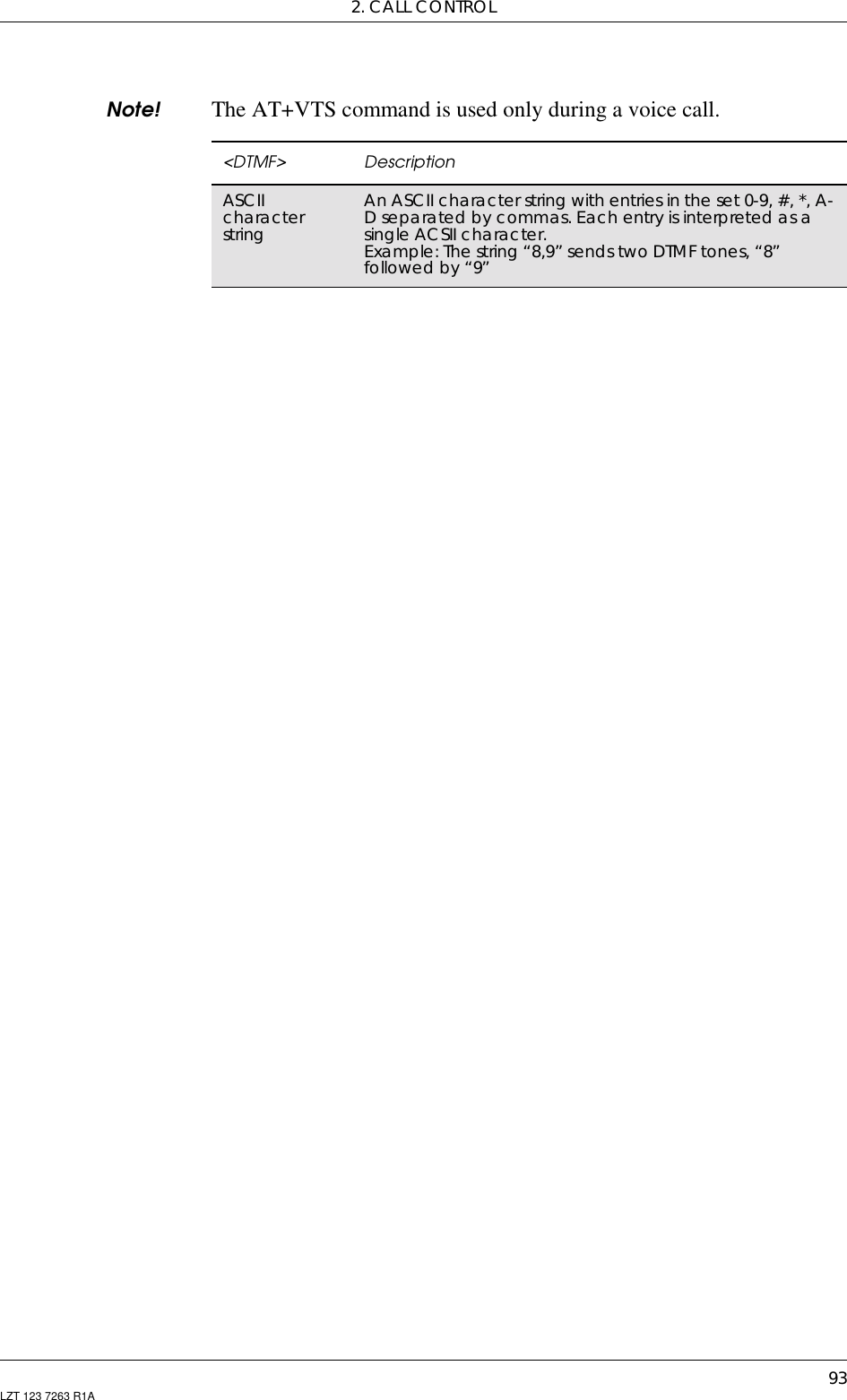
![GM47/GM48 INTEGRATOR’S MANUAL92 LZT 123 7263 R1A2.12 AT+CVHU Voice Hang-UpSelects whether ATH or “drop DTR” causes a voice connection to bedisconnected or not. Voice connection also includes alternating modecalls that are currently in voice mode.Note! When <mode>=2, this command must be viewed in conjunction withthe V.25ter [3] command &D, or &D will be ignored.2.13 AT+VTS DTMF and Tone GenerationThis command allows the transmission of DTMF tones. These tonesmay be used, for example, when announcing the start of a recordingperiod. The command is write only. In this profile of commands, thecommand does not operate in data or fax modes of operation(+FCLASS=0,1,2-7).Note! The ATD-command is used only for dialing. It is not possible togenerate arbitrary DTMF tones using the ATD command.Description Syntax Possible ResponsesSet Command +CVHU=[<mode>] •+CMEERROR:<err>•OKRead command +CVHU? •+CVHU:<mode>•+CMEERROR:<err>Test if the command issupported +CVHU=? +CVHU (list ofsupported <mode>s)<mode> Description0“Drop DTR” ignored but OK response given. ATHdisconnects1“Drop DTR” and ATH ignored but OK response given2“Drop DTR” behavior according to &D setting. ATHdisconnects. DefaultDescription Command Possible ResponsesRequest transmission ofDTMF tone(s) AT+VTS=<DTMF> OKERRORShow if the commandis supported AT+VTS=? OKERROR](https://usermanual.wiki/Sony/6220501-BV.Exhibit-8-Integrators-Manual/User-Guide-247869-Page-92.png)
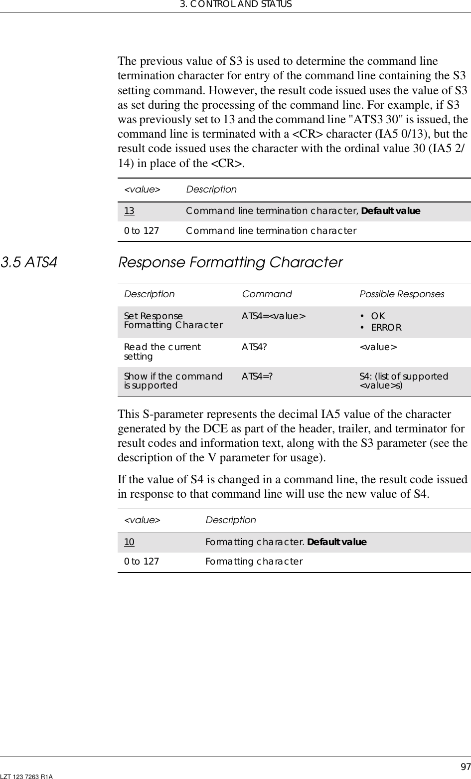
![95LZT 123 7263 R1A3. Control and Status3.1 ATQ Result Code SuppressionDetermines whether or not the DCE transmits result codes to the DTE.When result codes are being suppressed, no portion of any intermediate,final, or unsolicited result code - header, result text, line terminator, ortrailer - is transmitted.Note! The Ingo-module triggers on the response from ref. Point E. It istherefore not possible to turn off the response in ref. Point E.3.2 ATS0 Automatic Answer ControlDefines the automatic answering feature of the modem. A non-zerovalue specifies the number of rings before the call is answered.Description Command Possible ResponsesSet Result CodeSuppression ATQ[=]<value> •OK•ERRORRead the currentsetting ATQ? Q: <value>Show if the commandis supported ATQ=? Q: (list of supported<value>s)<value> Description0DCE transmits result codes. Default value1Result codes are suppressed and not transmittedDescription Command Possible ResponsesAutomatic answercontrol ATS0=[<rcnt>] •OK•ERRORRead the currentsetting ATS0? <rcnt>Show if the commandis supported ATS0=? S0: (list of supported<rcnt>s)](https://usermanual.wiki/Sony/6220501-BV.Exhibit-8-Integrators-Manual/User-Guide-247869-Page-95.png)
![GM47/GM48 INTEGRATOR’S MANUAL96 LZT 123 7263 R1ANote! Call is always answered in the current fax class, regardless of whetherthe incoming call is voice, data, or fax.3.3ATS2 EscapeSequenceCharacterDefines the character to be used as the escape sequence character whenswitching from on-line data mode to on-line command mode. Theresponse to the command is modified to reflect the change.Note! If the <esc> parameter is set to a value in the range of 128-255, theescape sequence detection is disabled.3.4 ATS3 Command Line Termination CharacterThis S-parameter represents the decimal IA5 value of the characterrecognised by the DCE from the DTE to terminate an incomingcommand line. It is also generated by the DCE as part of the header,trailer, and terminator for result codes and information text, along withthe S4 parameter.<rcnt> Description0Disable automatic answer. Default value1-7 Answer after the specified number of ringsDescription Command Possible ResponsesSet escape sequencecharacter ATS2=[<esc>] •OK•ERRORRead the currentsetting ATS2 <esc>Show if the commandis supported ATS2=? S2: (list of supported<esc>s)<esc> Description43 Escape sequence character. Default value0 to 255 Escape sequence characterDescription Command Possible ResponsesSet Command LineTermination Character ATS3=<value> •OK•ERRORRead the currentsetting ATS3? <value>Show if the commandis supported ATS3=? S3: (list of supported<value>s)](https://usermanual.wiki/Sony/6220501-BV.Exhibit-8-Integrators-Manual/User-Guide-247869-Page-96.png)
![GM47/GM48 INTEGRATOR’S MANUAL98 LZT 123 7263 R1A3.6 ATS5 Command Line Editing Character (BACKSPACE)This S-parameter represents the decimal IA5 value of the characterrecognised by the DCE as a request to delete from the command line theimmediately preceding character.3.7 ATS6 Blind Dial Delay ControlDefines the number of seconds to wait before call addressing when adial tone is not detected. This command is ignored by the InfraredModem and is only included for compatibility.Description Command Possible ResponsesRequest CommandLine Editing Character ATS5=<value> •OK•ERRORShows the currentsetting ATS5? <value>Show if the commandis supported ATS5=? S5: (list of supported<value>s)<value> Description8Line editing character. Default value0 to 127 Line editing characterDescription Command Possible ResponsesBlind dial delay control ATS6=[<dly>] OKRead the currentsetting ATS6? <dly>Show if the commandis supported ATS6=? S6: (list of supported<dly>s)<dly> Description2Wait two seconds before blind dialling.Default value.2-255 Number of seconds to wait before blind dialling](https://usermanual.wiki/Sony/6220501-BV.Exhibit-8-Integrators-Manual/User-Guide-247869-Page-98.png)
![3. CONTROL AND STATUS99LZT 123 7263 R1A3.8 ATS7 Connection Completion TimeoutDefines the maximum time allowed between completion of dialling andthe connection being established. If this time is exceeded then theconnection is aborted.3.9 ATS8 Comma Dial Modifier Delay ControlDescription Command Possible ResponsesSet connectioncompletion timeout ATS7=[<tmo>] •OK•ERRORRead the currentsetting ATS7? <tmo>Show if the commandis supported ATS7=? S7: (list of supported<tmo>s)<tmo> Description50 Timeout value in seconds. Default value1-255 Timeout value in secondsDescription Command Possible ResponsesSet Comma DialModifier Delay Control ATS8=[<dly>] •OK•ERRORRead the currentsetting. ATS8? <dly>Show if the commandis supported. ATS8=? S8: (list of supported<dly>s)<dly> Description2Thevalueofthedialmodifierdelayinseconds.Default value1-255 Thevalueofthedialmodifierdelayinseconds](https://usermanual.wiki/Sony/6220501-BV.Exhibit-8-Integrators-Manual/User-Guide-247869-Page-99.png)
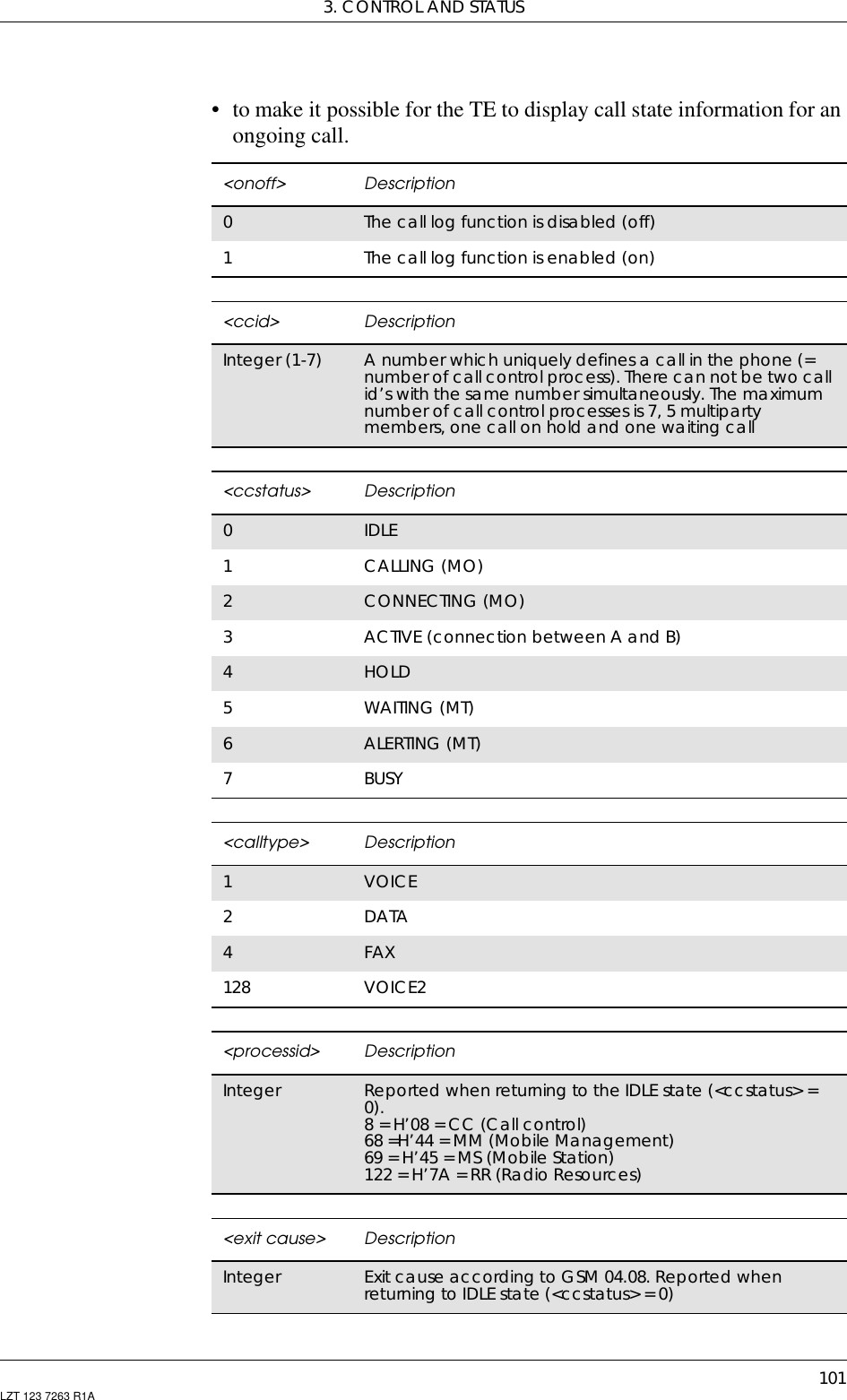
![GM47/GM48 INTEGRATOR’S MANUAL100 LZT 123 7263 R1A3.10 ATS10 Automatic Disconnect Delay ControlSpecifies the amount of time that the DCE will remain connected to theline after the absence of received line signals.3.11 AT*ECAM Ericsson Call MonitoringThis command activates or deactivates the call monitoring function inthe ME. When this log function is activated in the ME, the ME informsabout call events, such as incoming call, connected, hang up etc.It is preferable that the current status shall always be sent with resultcode *ECAV when activating the log function. The purpose of this istwo fold:• to gather relevant information for the call log in a TE;Description Command Possible ResponsesSet AutomaticDisconnect DelayControlATS10=[<val>] •OK•ERRORRead the currentsetting ATS10? <val>Show if the commandis supported ATS10=? S10: (list of supported<val>s)<val> Description2Remains connected for two tenths of a second. Default value1-254 Number of tenths of a second of delayDescription Command Possible ResponsesSet Call Monitoring onor off AT*ECAM=<onoff> •OK•+CMEERROR:<err>•OK•ERRORRead the current statusfor Call Monitoring AT*ECAM? •*ECAM:<onoff>•+CMEERROR:<err>•OK•ERRORTest if the command issupported AT*ECAM=? •*ECAM:listofsupported <onoff>s•+CMEERROR:<err>•OK•ERROR](https://usermanual.wiki/Sony/6220501-BV.Exhibit-8-Integrators-Manual/User-Guide-247869-Page-100.png)
![3. CONTROL AND STATUS105LZT 123 7263 R1AThe alarm function uses the ring type and the ring level defined with theAT*ERIN and AT*ERIL commands.3.17 AT+CALD Alarm DeleteThis command removes an active alarm.3.18 AT+CAPD Postpone or Dismiss an AlarmThis command controls an active (occurring) alarm by eitherpostponing it or dismissing it.If more than one alarm occurs at the same time, this command dismissesor postpones the last activated alarm.<time> Descriptionstring typevalue Refer to AT+CCLK command. Only minutes and hours areusedDescription Command Possible ResponsesDelete an alarm AT+CALD=<n> •+CMEERROR:<err>•OK•ERRORShow if the commandis supported AT+CALD=? •+CALD:(listofsupported <n>s)•+CMEERROR:<err>•OK•ERROR<n> DescriptionInteger type Index identifying an active alarmDescription Command Possible ResponsesPostpone or dismiss analarm AT+CAPD=[<sec>] •+CMEERROR:<err>•OK•ERRORShow if the commandis supported AT+CAPD=? •+CAPD:(listofsupported <sec>s)•+CMEERROR:<err>•OK•ERROR<sec> Description0Dismiss the alarm1…600 Postpone the alarm (snooze) for <sec> seconds. Notsupported540 Postpone the alarm (snooze) for 540 seconds (9 minutes).This is the only supported value](https://usermanual.wiki/Sony/6220501-BV.Exhibit-8-Integrators-Manual/User-Guide-247869-Page-105.png)
![3. CONTROL AND STATUS107LZT 123 7263 R1A3.21 AT+CFUN Set Phone FunctionalitySelects the level of functionality <fun> in the MS. Level “fullfunctionality” results in the highest level of power drawn. “Minimumfunctionality” resultsin the minimum power drawn. Manufacturers mayalso specify levels of functionality between these two end levels. Whensupported by manufacturers, ME resetting with the <rst> parametermay be utilized.Test command returns values supported by the ME as a compound.Note! ‘AT+CFUN=’ is interpreted as ‘AT+CFUN=0’.Description Command Possible ResponsesSet MS functionality AT+CFUN=[<fun>[,<rst>]] •+CMEERROR:<err>•OKShow the currentsetting AT+CFUN? •+CFUN:<fun>•+CMEERROR:<err>Show if thecommand issupportedAT+CFUN=? • +CFUN: (list ofsupported <fun>s),(list of supported<rst>s)•+CME ERROR: <err><fun> Description0Minimum functionality. Default value.Note: The ME is turned off1Full functionality.Note: If previously turned off, the phone is turned on4Disable MS transmit and receive RF circuitsNot Supported<rst> Description0Do not reset1Reset the MS before setting it to <fun> power level](https://usermanual.wiki/Sony/6220501-BV.Exhibit-8-Integrators-Manual/User-Guide-247869-Page-107.png)
![GM47/GM48 INTEGRATOR’S MANUAL108 LZT 123 7263 R1A3.22 AT+CIND Indicator ControlUsed to set the values of ME indicators. <ind> value 0 means that theindicator is off (or in state which can be identified as “off” state), 1means that indicator is on (or in a state which is more substantial than“off” state), 2 is more substantial than 1, and so on. If the indicator is asimple on/off style element, it has values 0 and 1. The number ofelements is ME specific. If the ME does not allow setting of indicatorsor it is not currently reachable, +CME ERROR: <err> is returned. If acertain indicator is not writable, it cannot be set. If the parameter is anempty field, the indicator will keep the previous value.Test command returns pairs, where string value <descr> is a maximum16 character description of the indicator and compound value is theallowed values for the indicator. If ME is not currently reachable,+CME ERROR: <err> is returned.Description Command Possible ResponsesSet IndicatorControl AT+CIND=[<ind>[,<ind>[,…]]] •+CMEERROR:<err>•OK•ERRORRead the currentsetting AT+CIND? • +CIND: <ind>,<ind>,…•+CMEERROR:<err>•OK•ERRORTest if thecommand issupportedAT+CIND=? • +CIND: (<descr>,(list ofsupported <ind>s)),(<descr>,(list of supported<ind>s)),…•+CMEERROR:<err>•OK•ERROR<ind> DescriptionInteger type Value shall be in range of corresponding <descr><descr> Description“battchg” Battery charge level (0-5) Not supported“signal” Signal quality (0-5)“battery warning” Battery warning (0-1) Not supported“charger connected” Charger connected (0-1) Not supported“service” Service availability (0-1)(Net contact status, 1 = Net contact)“sounder” Sounder activity (0-1)(ME silent status, 1 = ME silent)“message” Message received (0-1)](https://usermanual.wiki/Sony/6220501-BV.Exhibit-8-Integrators-Manual/User-Guide-247869-Page-108.png)
![3. CONTROL AND STATUS109LZT 123 7263 R1A3.23 AT+CLAC List all available AT CommandsCauses the ME to return one or more lines of AT commands.Note! This command only returns the AT commands that are available to theuser.3.24 AT+CMEE Mobile Equipment ErrorDisables or enables the use of result code +CME ERROR: <err> as anindication of an error relating to the functionality of the ME. Whenenabled, ME related errors cause +CME ERROR: <err> final resultcode instead of the regular ERROR final result code. ERROR isreturned normally when error is related to syntax, invalid parameters, orTA functionality.“call” Call in progress (0-1)“vox” Transmit activated by voice activity (0-1).Not supported“roam” Roaming indicator (0-1)(Home net status, 0 = Home Net)“sms full” A short message memory storage in the MT hasbecome full (1), or memory locations areavailable(0);i.e.therangeis(0-1)<descr> DescriptionCommand Possible Responses+CLAC <ATCommand1>[<CR><LF><ATCommand2>[…]]+CME ERROR: <err>+CLAC=? +CME ERROR: <err>Description Command Possible ResponsesRequest GSM MobileEquipment ErrorControlAT+CMEE=[<n>] •OK•ERRORRead the command AT+CMEE? • +CMEE: <n>•OK•ERRORShow if the commandis supported AT+CMEE=? • +CMEE: (list ofsupported <n>s)•OK•ERROR](https://usermanual.wiki/Sony/6220501-BV.Exhibit-8-Integrators-Manual/User-Guide-247869-Page-109.png)
![GM47/GM48 INTEGRATOR’S MANUAL110 LZT 123 7263 R1A3.25 AT+CMER Mobile Equipment Event ReportingEnables or disables the sending of unsolicited result codes from ME toTE in the case of key pressings, display changes, and indicator statechanges. <mode> controls the processing of unsolicited result codesspecified within this command. <bfr> controls the effect on bufferedcodes when <mode> 1, 2 or 3 is entered. If the ME does not supportsetting, +CME ERROR: <err> is returned.<n> Description0Disable +CME ERROR: <err> result code and use ERRORinstead. Default value1Enable +CME ERROR: <err> result code and use numeric<err> values (refer next subclause)2Enable +CME ERROR: <err> result code and use verbose<err> values (refer next subclause)Description Command Possible ResponsesSet phoneactivity status AT+CMER=[<mode>[,<keyp>[,<disp>[,<ind>[,<bfr>]]]]]•+CMEERROR:<err>•OK•ERRORRead thecurrent setting AT+CMER? •+CMER:<mode>,<keyp>,<disp>,<ind>,<bfr>•OK•ERRORTest if thecommand issupportedAT+CMER=? • +CMER: (list of supported<mode>s), (list of supported<keyp>s), (list of supported<disp>s), (list of supported<ind>s), (list of supported<bfr>s)•OK•ERROR<mode> Description0Buffer unsolicited result codes in the TA; if TA result codebuffer is full, codes can be buffered in some other placeor the oldest ones can be discarded1Not Supported2Not Supported3Forward unsolicited result codes directly to the TE; TA-TElink specific inband technique used to embed resultcodes and data when TA is in on-line data mode<keyp> Description0No keypad event reporting](https://usermanual.wiki/Sony/6220501-BV.Exhibit-8-Integrators-Manual/User-Guide-247869-Page-110.png)
![3. CONTROL AND STATUS111LZT 123 7263 R1A3.26 AT+CPAS Phone Activity StatusReturns the activity status <pas> of the ME. It can be used to interrogatethe ME before requesting action from the phone.When the command is executed without the <mode> argument, thecommand returns <pas>-values from 0 to 128 (for supported values setable 1 below). When, on the other hand, the command is executed withthe <mode> argument set to 1, the command may return Ericssonspecific <pas> values from 129 to 255 (for supported values see thetable below).<disp> Description0No display event reporting<ind> Description0No indicator event reporting1Indicator event reporting using result code +CIEV:<ind>,<value>.<ind> indicates the indicator order number(asspecifiedfor+CIND)and<value>isthenewvalueofindicator. Only those indicator events, which are notcaused by +CIND shall be indicated by the TA to the TE2Not Supported<bfr> Description0TA buffer of unsolicited result codes defined within thiscommand is cleared when <mode> 1...3 is entered1TA buffer of unsolicited result codes defined within thiscommand is flushed to the TE when <mode> 1...3 isentered (OK response shall be given before flushing thecodes). Not SupportedDescription Command Possible ResponsesExecute Phone ActivityStatus AT+CPAS[=<mode>] •+CPAS:<pas>• +CME ERROR <err>•OK•ERRORTest if the command issupported AT+CPAS=? •+CPAS:(list of supported<pas>s)• +CME ERROR <err>•OK•ERROR](https://usermanual.wiki/Sony/6220501-BV.Exhibit-8-Integrators-Manual/User-Guide-247869-Page-111.png)
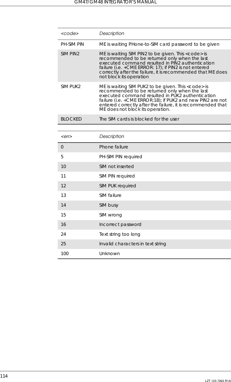
![3. CONTROL AND STATUS113LZT 123 7263 R1A3.27 AT+CPIN PIN ControlSends the password to the ME, which is necessary to make the MEoperational (SIM PIN, SIM PUK or PH-SIM). If the PIN is to be enteredtwice, the TA autonomously repeats the PIN. If no PIN request ispending, no action is taken towards the ME and an error message(+CME ERROR <err>) is returned to the TE.If the PIN required is PUK, the second pin is required. This second PIN,<newpin>, is used to replace the old PIN in the SIM.Note! Commands which interact with the ME that are accepted when the MEhas a pending request for SIM PIN, SIM PUK or PH-SIM are: +CGMI,+CGMM, +CGMR, +CGSN, +CFUN, +CMEE +CPIN, L and M.Description Command Possible ResponsesRequest PIN Control AT+CPIN=<pin>[,<newpin>] •+CMEERROR:<err>•OK•ERRORShow the currentsetting AT+CPIN? •+CPIN:<code>•+CMEERROR:<err>•OK•ERRORShow if the commandis supported AT+CPIN=? •+CMEERROR:<err>• +CPIN: (supported<code>s)•OK•ERROR<pin>,<newpin> Descriptionstring The range for the SIM PIN and the PH- SIM PIN is 4 - 8digits. The SIM PUK consists of 8 digits<code> DescriptionREADY ME is not pending for any passwordSIM PIN ME is waiting SIM PIN to be givenSIM PUK ME is waiting SIM PUK to be given](https://usermanual.wiki/Sony/6220501-BV.Exhibit-8-Integrators-Manual/User-Guide-247869-Page-113.png)
![3. CONTROL AND STATUS117LZT 123 7263 R1A3.29 AT+CR Service Reporting ControlEnables or disables display of intermediate bearer capability reportsduring the handshake phase.3.30 AT+CRC Cellular Result CodeControls whether or not the extended format of incoming call indicationis used. When enabled, an incoming call is indicated to the TE withunsolicited result code +CRING: <type> instead of the normal RING.Test command returns values supported by the TA as a compoundvalue.Description Command Possible ResponsesSet Service ReportingControl AT+CR=<mode> •OK•ERRORRead current setting AT+CR? •+CR:<mode>•OK•ERRORTest if the command issupported AT+CR=? •+CR:(listofsupported<mode>s)•OK•ERROR<mode> Description0Disable reporting. Default value1Enable reportingDescription Command Possible ResponsesSet Cellular ResultCode option AT+CRC=[<mode>] •OK•ERRORShow the currentsetting AT+CRC? •+CRC:<mode>•OK•ERRORShow if the commandis supported AT+CRC=? •+CRC:(listofsupported<mode>s)•OK•ERROR<mode> Description0Disables extended format1Enables extended format](https://usermanual.wiki/Sony/6220501-BV.Exhibit-8-Integrators-Manual/User-Guide-247869-Page-117.png)
![GM47/GM48 INTEGRATOR’S MANUAL118 LZT 123 7263 R1A3.31 AT+CSAS Save SettingsSaves active message service settings to a non-volatile memory. A TAcan contain several settings profiles. Settings specified in commandsService Centre Address +CSCA, Set Message Parameters +CSMP andSelect Cell Broadcast Message Types +CSCB (if implemented) aresaved. Certain settings may not be supported by the storage (e.g. SIMSMS parameters) and therefore can not be saved.Test command shall display the supported profile numbers for readingand writing of settings.3.32 AT+CSQ Signal StrengthReturns the received signal strength indication <rssi> and channel biterror rate <ber> from the ME. Test command returns values supportedby the TA as compound values.Description Command Possible ResponsesSave Settings AT+CSAS[=<profile>] • +CMS ERROR: <err>•OK•ERRORGet availableprofiles AT+CSAS=? • +CSAS: (list of supported<profile>s)• +CMS ERROR: <err>•OK•ERROR<profile> Description0..255 Manufacturer specific profile number where settings areto be stored. Default is “0”.Description Command Possible ResponsesExecute SignalStrength AT+CSQ •+CSQ:<rssi>,<ber>• +CME ERROR <err>•OK•ERRORTest if the command issupported AT+CSQ=? •+CSQ:(listofsupported<rssi>s),(list ofsupported <ber>s)• +CME ERROR <err>•OK•ERROR](https://usermanual.wiki/Sony/6220501-BV.Exhibit-8-Integrators-Manual/User-Guide-247869-Page-118.png)
![3. CONTROL AND STATUS119LZT 123 7263 R1A3.33 AT+CTZU Automatic Time Zone UpdateEnables and disables the automatic time zone update via NITZ. Ifsetting fails in an ME error, +CME ERROR <err> is returned.<rssi> Description0-113dBm or less1-111dBm2..30 -109… –53dBm31 -51dBm or greater99 Notknownornotdetectable<ber> Description0..7 As RXQUAL values in the table in GSM 05.08 [0] subclause8.2.499 NotknownornotdetectableDescription Command Possible ResponsesEnable and disableautomatic time zoneupdate via NITZAT+CTZU=<onoff> •+CMEERROR:<err>•OK•ERRORRead current setting AT+CTZU? •+CTZU:<onoff>•+CMEERROR:<err>•OK•ERRORShow if the commandis supported AT+CTZU=? •+CTZU:(listofsupported <onoff>s)•+CMEERROR:<err>•OK•ERROR<onoff> Description0The automatic time zone update is disabled (off)1The automatic time zone update is enabled (on)](https://usermanual.wiki/Sony/6220501-BV.Exhibit-8-Integrators-Manual/User-Guide-247869-Page-119.png)

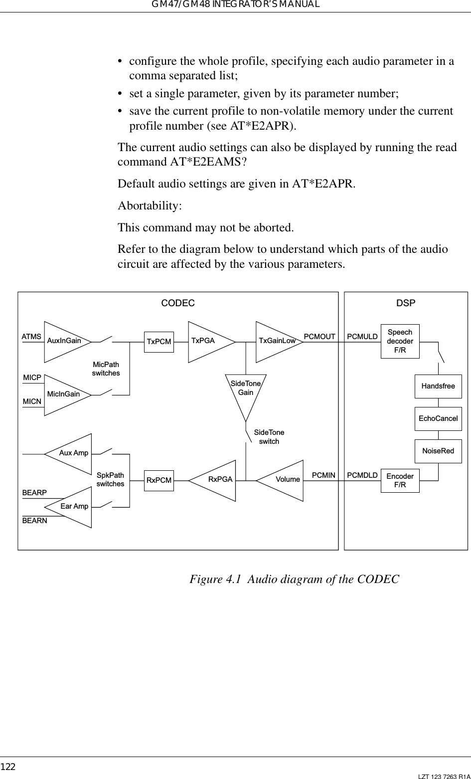
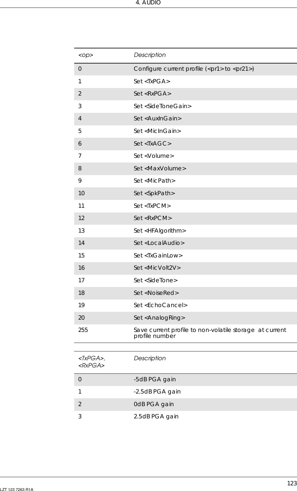
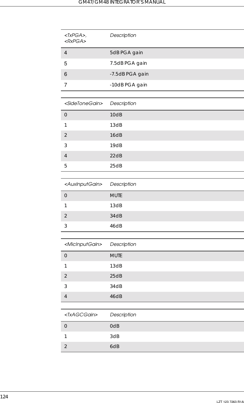
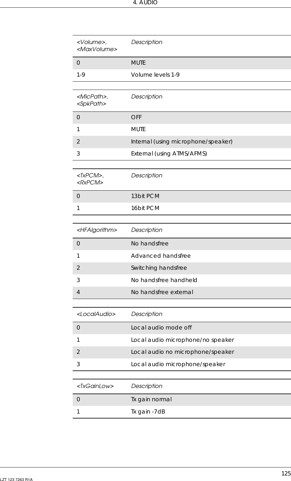
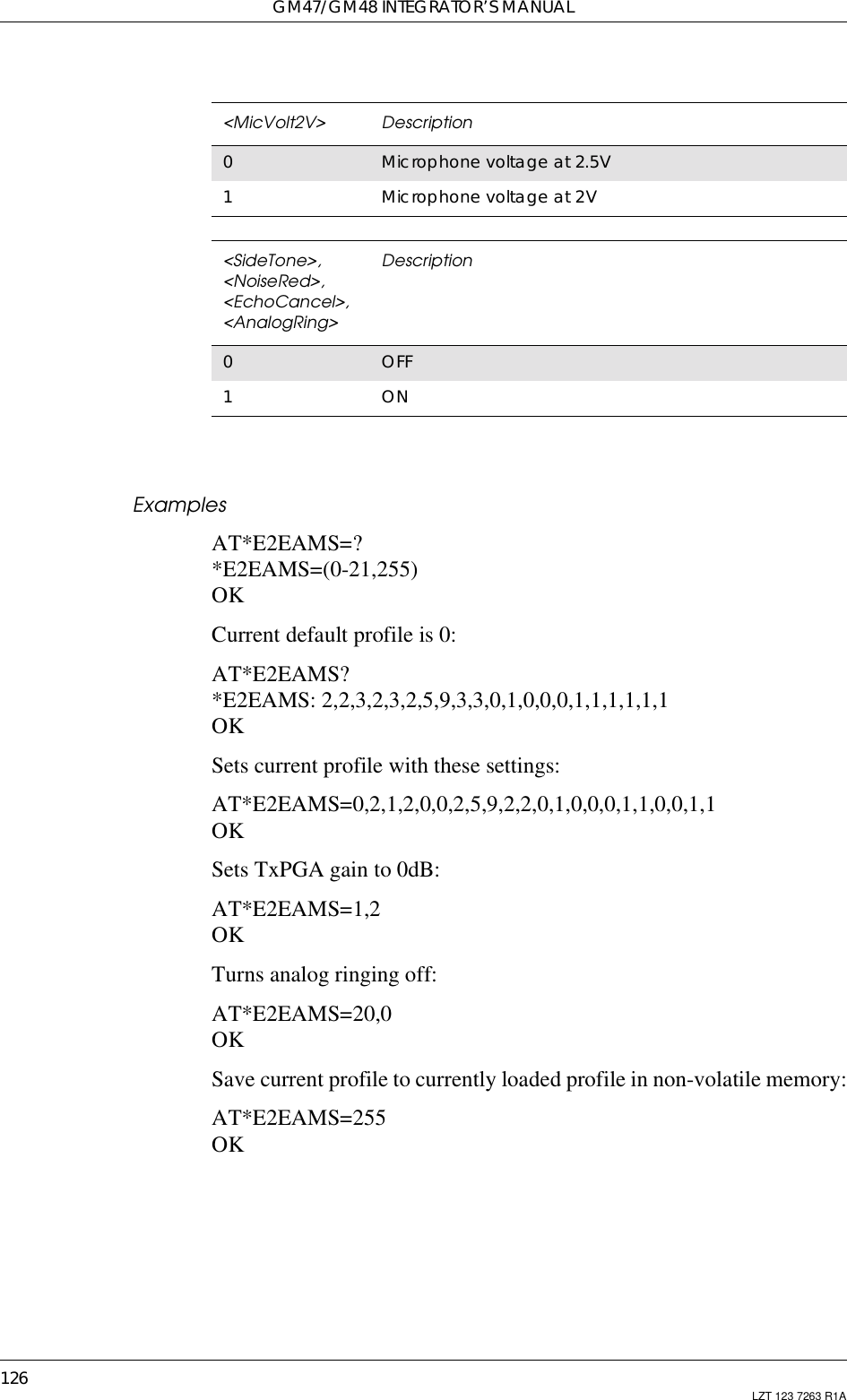
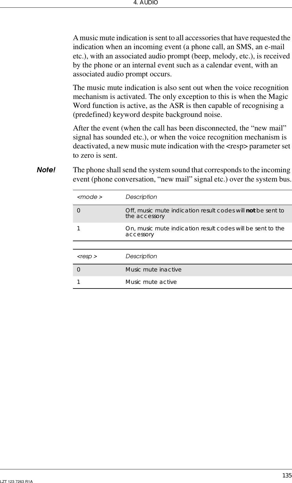
![121LZT 123 7263 R1A4. AudioNote! *E2EAMS and *E2APR are new commands that replace thefuntionality offered by the *EALR, *EAMS, *EARS and *ELAMcommands. Use the new commands in new applications. The oldcommands are included for compatibility.4.1 AT*E2EAMS Ericsson M2M Audio Profile ModificationThis command allows the modification and configuration of the currentaudio profile. An audio profile is a set of data which uniquely definesthe way in which the audio paths, gains, DSP algorithms and switchsetting are configured. There are several audio profiles available innon-volatile storage, and the current profile can be modified by use ofthe AT*E2APR command.The AT*E2EAMS command allows the user to:Description Command Possible ResponsesRequestoperationwith audioprofileAT*E2EAMS= <op>[,<TxPGA>,<RxPGA>,<SideToneGain>,<AuxInGain>,<MicInGain>,<TxAGC>,<Volume>,<MaxVolume>,<MicPath>,<SpkPath>,<TxPCM>,<RxPCM>,<HFAlgorithm>,<LocalAudio>,<TxGainLow>,<MicVolt2V>,<SideTone>,<NoiseRed>,<EchoCancel>,<AnalogRing>,][,<val>]]• ERROR•OKDisplay setprofile AT*E2EAMS? • *E2EAMS: <TxPGA>,<RxPGA>,<SideToneGain>,<AuxInGain>,<MicInGain>,<TxAGC>,<Volume>,<MaxVolume>,<MicPath>,<SpkPath>,<TxPCM>,<RxPCM>,<HFAlgorithm>,<LocalAudio>,<TxGainLow>,<MicVolt2V>,<SideTone>,<NoiseRed>,<EchoCancel>,<AnalogRing>• ERRORShow if thecommandis supportedAT*E2EAMS=? • *E2EAMS:(list of supported <op>s)• ERROR](https://usermanual.wiki/Sony/6220501-BV.Exhibit-8-Integrators-Manual/User-Guide-247869-Page-121.png)
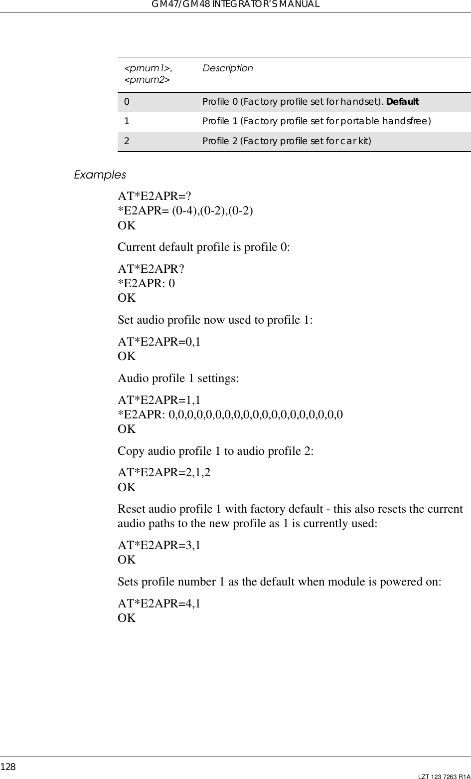
![4. AUDIO127LZT 123 7263 R1A4.2 AT*E2APR M2M Audio Profile ManipulationThis command allows the maniuplation and storage of the audio“profiles” stored in the MS. The requirement for the 2nd and 3rdparameters depend on the operation being carried out.Using the command you can:• Set one of the three audio profiles 0, 1 or 2 as the current profile.This will load the profile's settings from NVM and implement them.• Read one of the audio profiles. The current settings for the profilenumber defined will be displayed.• Copy all parameters from one profile into another.• Reset any of the profiles. This will reinstate the factory defaults forthe profile:- 0 is the handset profile,- 1 is the portable handsfree profile,- 2 is the car kit profile.• Set a profile as the default profile on next power up.Description Command Possible ResponsesRequest operationwith audio profile AT*E2APR=<op>[,<prnum1>[,<prnum2>]]• ERROR•OK• *E2APR: <TxPGA>,<RxPGA>,<SideToneGain>,<AuxInGain>,<MicInGain>,<TxAGC>,<Volume>,<MaxVolume>,<MicPath>,<SpkPath>,<TxPCM>,<RxPCM>,<HFAlgorithm>,<LocalAudio>,<TxGainLow>,<MicVolt2V>,<SideTone>,<NoiseRed>,<EchoCancel>,<AnalogRing>•OKDisplay currentlyset profile AT*E2APR? • *E2APR: current <prnum>•ERRORShows if thecommand issupportedAT*E2APR=? •*E2APR:(listofsupported<op>s), (list of supported<prnum1>s), (list of supported<prnum2>s)• ERROR<op> Description0Set profile <prnum1> to set as current1Read profile <prnum1> settings2Copy profile <prnum1> to <prnum2>3Reset profile <prnum1> to factory default4Set default profile as <prnum1>. Will store this as defautlprofile in NVM, and use it as default from next power on](https://usermanual.wiki/Sony/6220501-BV.Exhibit-8-Integrators-Manual/User-Guide-247869-Page-127.png)
![4. AUDIO129LZT 123 7263 R1A4.3 AT*EALR Ericsson Audio Line RequestThe AT*EALR command is used by accessories to request the ATMSand AFMS. The command includes two parameters; <mode> and<activation>. The <mode> parameter sets which audio lines arerequested and the <activation> parameter is used to indicate if theaccessory wants to be activated directly or not. Direct activation meansthe accessory gets the audio lines immediately if a call is establishedfrom the MS (i.e. keypad, voice recognition). If the accessory doesn'trequest direct activation, it has to indicate to the MS when it wants toget the audio lines (e.g. using AT commands).The <audio status> parameter is used to demand the audio lines.This command enables the unsolicited result code*EALV:<mode>,<activation>,<resp> which is sent to the applicationwhen the module wants it to change audio state.Description Command Possible ResponsesRequest the audio lines(ATMS,AFMS) AT*EALR=<mode>[,<activation>[,<aud_status>]]•*EALR:<mode>,<activation>,<resp>•OK•ERRORShow the currentsetting AT*EALR? *EALR:<mode>,<activation>,<resp>Show list of supportedparameters AT*EALR=? *EALR:(list of supported<mode>s,<activation>s and<aud_status>sparameters)<mode > Description0No request for ATMS or AFMS1Request ATMS and not AFMS2RequestAFMSandnotATMS3Request ATMS and AFMS<activation > Description0Not direct activated audio accessory (e.g. cordlessportable hands free)1Direct activated audio accessory (e.g. vehicle handsfree)](https://usermanual.wiki/Sony/6220501-BV.Exhibit-8-Integrators-Manual/User-Guide-247869-Page-129.png)
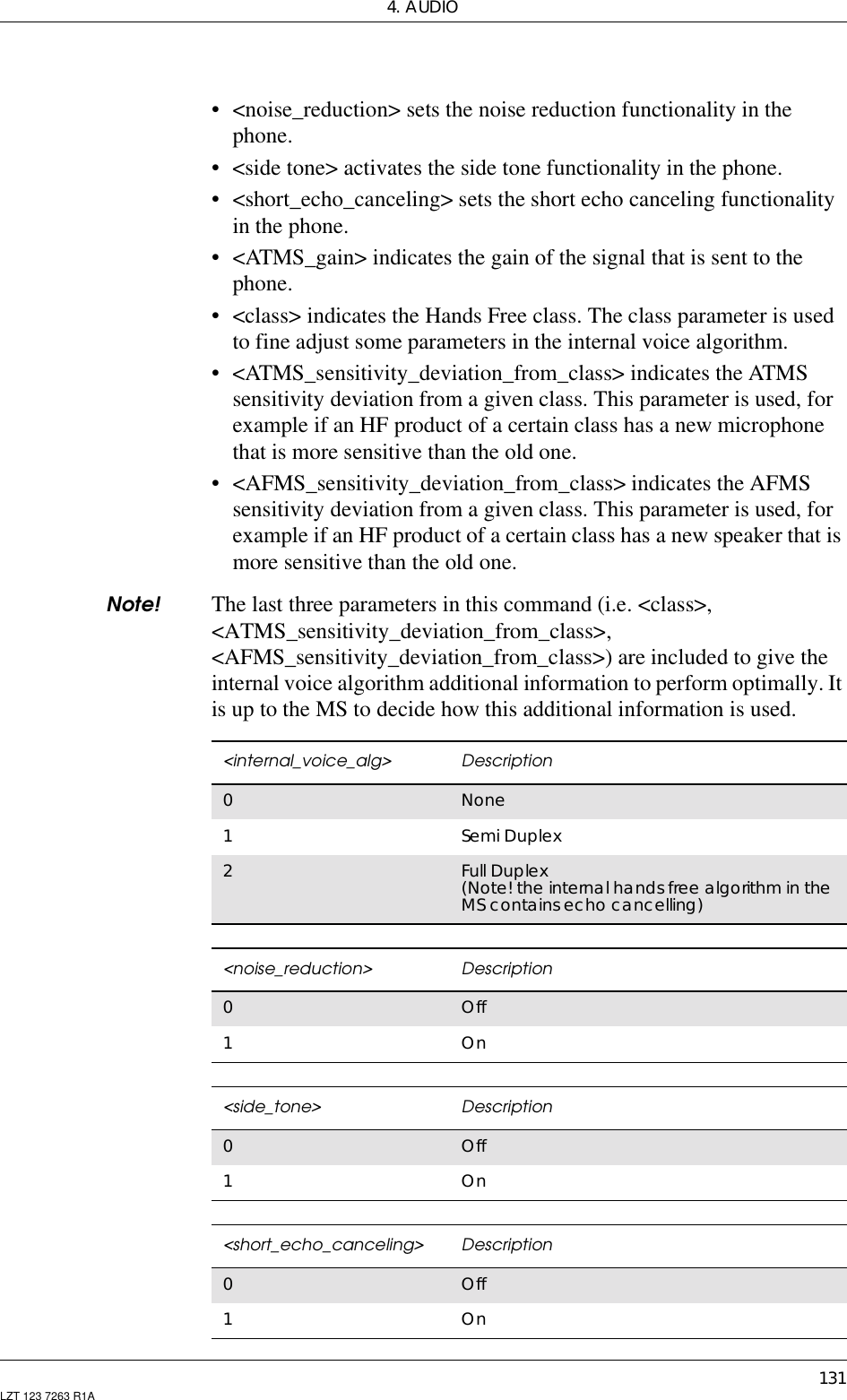
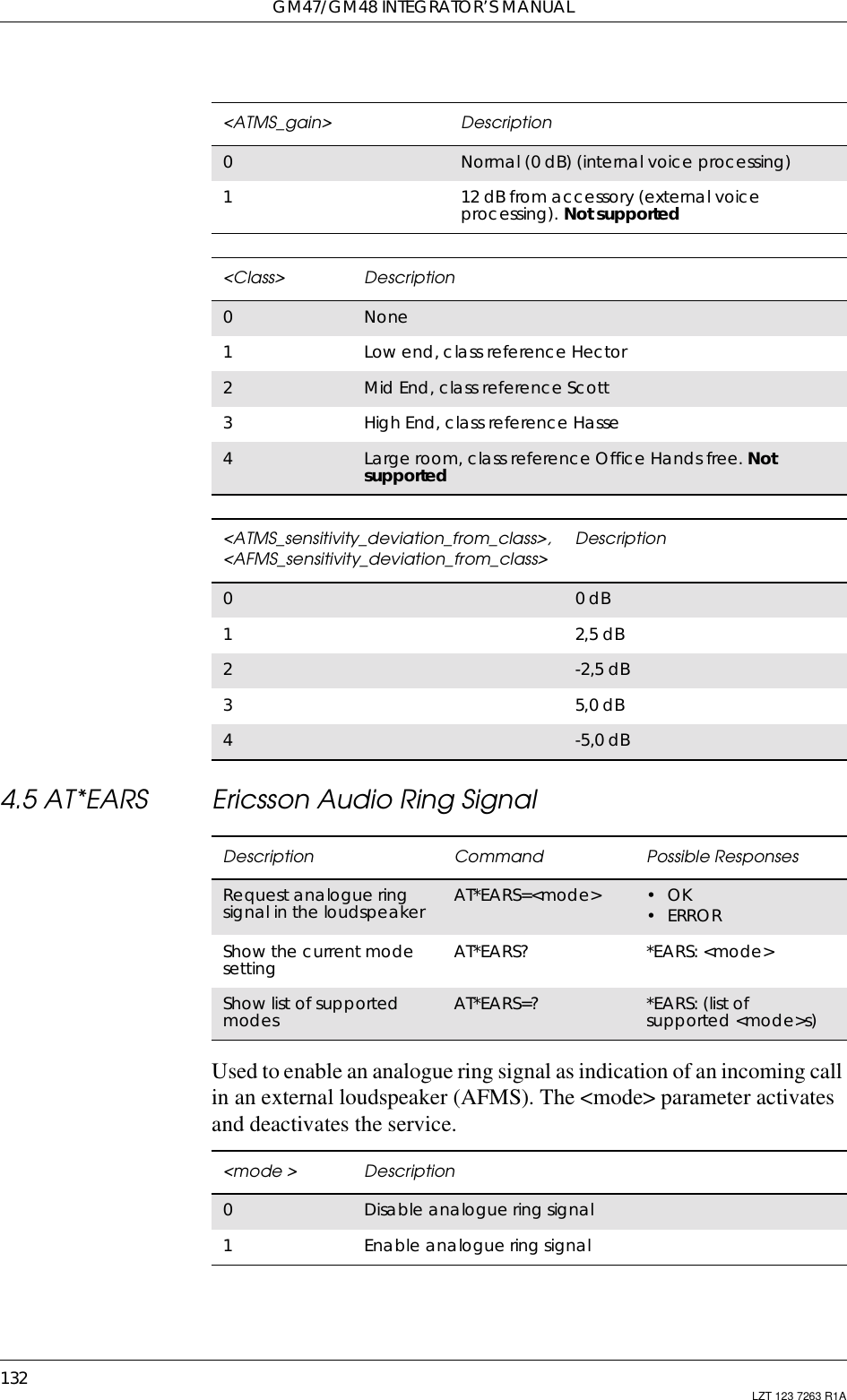
![GM47/GM48 INTEGRATOR’S MANUAL130 LZT 123 7263 R1A4.4 AT*EAMS Ericsson Audio Mode SelectionSet the Audio mode selection.The command must be sent to the MS at the initialization of an audioaccessory, but can also be sent later to change the audio mode selection.The command includes the following parameters:• <internal_voice_alg> sets the voice-processing mode in the phone.<aud_status > Description0No change of the audio status1Audio hand over. Accessory hands over control of boththe audio lines and the call to the phone2Audio demand. Accessory demands control of both theaudio lines and the call<resp > Description0Disable ATMS and AFMS1Enable ATMS and disable AFMS2Disable ATMS and enable AFMS3Enable ATMS and AFMSDescription Command Possible ResponsesSetstheaudiomode for theapplicationAT*EAMS=<internal_voice_alg>[,<noise_reduction>[,<side tone>[,<short_echo_canceling>[,<ATMS_gain>[,<class>[,<ATMS_sensitivity_deviation_from_class>[,<AFMS_sensitivity_deviation_from_class>]]]]]]]•OK•ERRORShow thecurrent audiomode settingAT*EAMS? *EAMS:<internal_voice_alg>, <noise_reduction>,<side_tone>,<short_echo_canceling>,<AFMS_gain>,<class>,<ATMS_sensitivity_deviation_from_class>,<AFMS_sensitivity_deviation_from_class>Show list ofsupportedservicesAT*EAMS=? *EAMS: (list of supported<internal_voice_alg >s,<noise_reduction>s,<side_tone>s,<short_echo_canceling>s,<AFMS_gain>s>,<class>s,<ATMS_sensitivity_deviation_from_class>s,<AFMS_sensitivity_deviation_from_class>s)](https://usermanual.wiki/Sony/6220501-BV.Exhibit-8-Integrators-Manual/User-Guide-247869-Page-130.png)
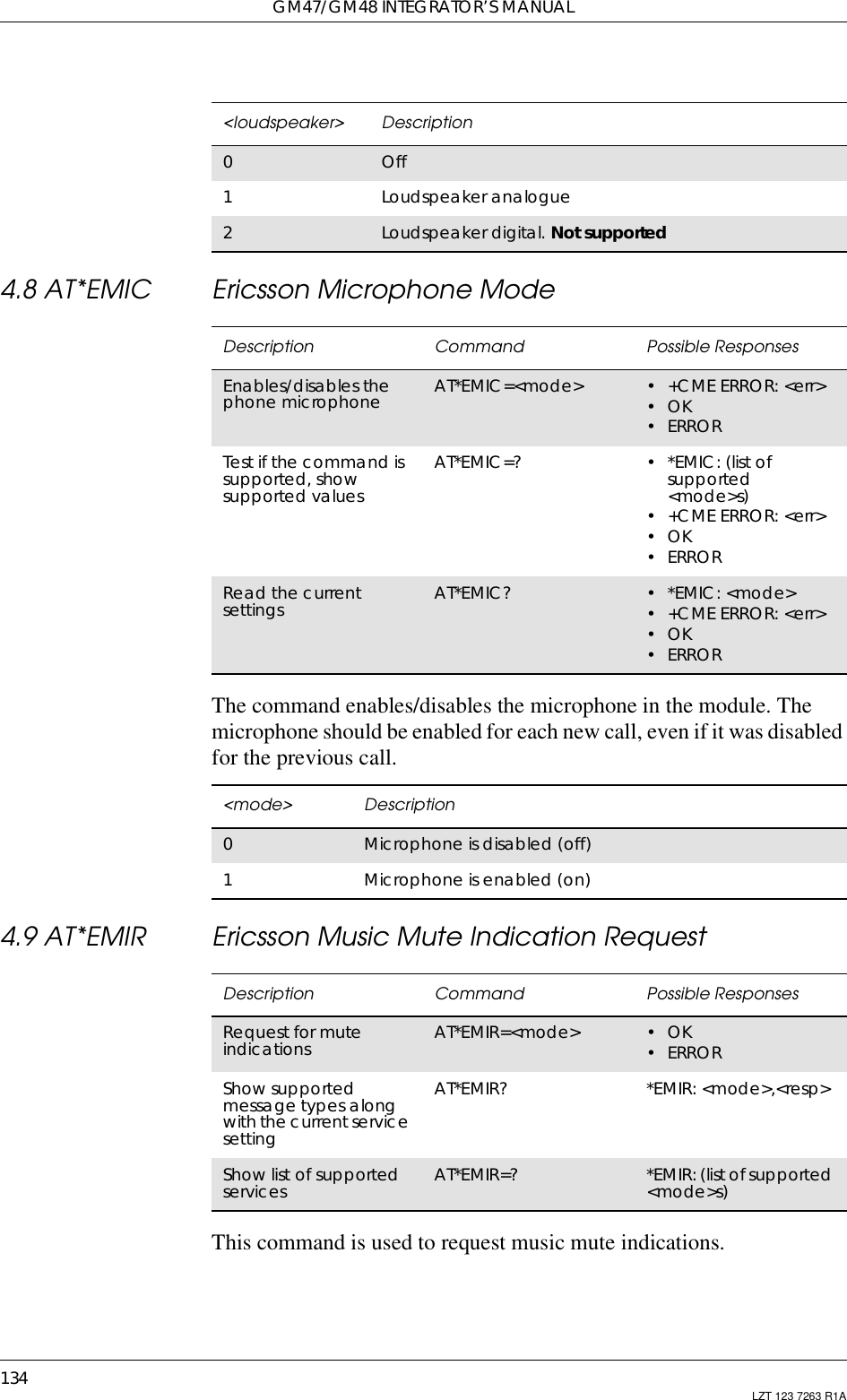
![4. AUDIO133LZT 123 7263 R1A4.6 AT*E2PHFB Portable Handsfree Button Sense EnableThis command allows the user to set the functionality for a PHF(portable handsfree) button, as used on simple handsfree equipment.When set to ON, the MS will detect the shortcircuit of the ATMS andAFMS lines, and interpret this as a PHF button press. This has the effectof answering/hanging up a call without recourse to AT commands.4.7 AT*ELAM Ericsson Local Audio ModeUsed to route the microphone and/or the loudspeaker signal to thesystem bus. This function is used when the audio information is to becommunicated over the system bus rather than the GSM radio. Thisfunctionality can be used by an MC link accessory that communicateswith a PSTN adapter.Description Command Possible ResponsesSet PHF functionality AT*E2PHFB=<op> •ERROR•OKDisplay current setting AT*E2PHFB? *E2PHFB: <op>Show if the commandis supported AT*E2PHFB=? •*E2PHFB:(listofsupported <op>s•ERROR<op> Description0Disable PHF button. Default setting1Enable PHF buttonDescription Command Possible ResponsesSet local audio mode AT*ELAM=<mic>[,<loudspeaker>] •*ELAM:<mic>,<loudspeaker>•OK•ERRORShow the currentservice setting AT*ELAM? *ELAM:<mic>,<loudspeaker>Show list of supportedparameters AT*ELAM=? *ELAM: (list ofsupported <mic>s and<loudspeaker>sparameters)<mic> Description0Off1Microphone analogue2Microphone digital. Not supported](https://usermanual.wiki/Sony/6220501-BV.Exhibit-8-Integrators-Manual/User-Guide-247869-Page-133.png)
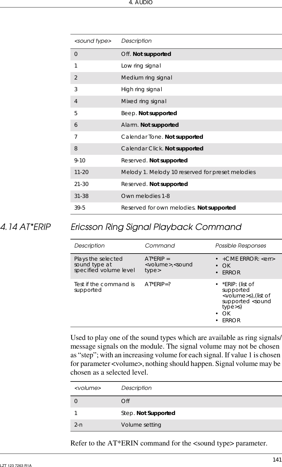
![GM47/GM48 INTEGRATOR’S MANUAL136 LZT 123 7263 R1A4.10 AT*EPRR Ericsson Personal Ring Type ReadReturns phone number, phone number type and sound type in locationnumber <indexr>. If listing fails an error, +CME ERROR: <err>, isreturned.Description Command Possible ResponsesRead phone numberand ring type AT*EPRR=<indexr> •*EPRR:<indexr>,<number>,<type>,<soundtype>• +CME ERROR <err>•OK•ERRORShow if the commandis supported AT*EPRR=? •*EPRR:(listofsupported<indexr>s)• +CME ERROR <err>•OK•ERROR<indexr> Description1-50 Value of location number<number> Descriptionstring type Phone number of format <type><type> Descriptioninteger format Type of address octet(refer GSM 04.08 [4] section 10.5.4.7)128 Unknown numbering plan, national / international numberunknown129 ISDN / telephony numbering plan, national / internationalunknown145 ISDN / telephony numbering plan, international number161 ISDN / telephony numbering plan, national number128 - 255 Other values refer GSM 04.08 [4] section 10.5.4.7<sound type> Description0Off. Not supported1Low ring signal2Medium ring signal3High ring signal4Mixed ring signal](https://usermanual.wiki/Sony/6220501-BV.Exhibit-8-Integrators-Manual/User-Guide-247869-Page-136.png)
![4. AUDIO137LZT 123 7263 R1A4.11 AT*EPRW Ericsson Personal Ringtype WriteWrites phone number, phone number type and sound type in locationnumber <indexr>. It is possible to use wild cards for phone number bysubstituting the digits with question marks. If writing fails an error,+CME ERROR: <err>, is returned.If all parameters but <indexr> are omitted, the personal ring type atposition <indexr> will be deleted.5Beep. Not supported6Alarm. Not supported7Calendar Tone. Not supported8Calendar Click. Not supported9-10 Reserved. Not supported11 Melody 112-20 Melody 2. Melody 10 reserved for pre-set melodies21-30 Reserved for melody 11-20. Not supported31-38 Own melody 1-839-50 Reserved for own melodies. Not supported<sound type> DescriptionDescription Command Possible ResponsesRequest PersonalRingtype WritecommandAT*EPRW=<indexr>,<number>,[<type>],<soundtype>• +CME ERROR <err>•OK•ERRORShow if the commandis supported AT*EPRW=? •*EPRW:(listofsupported<indexr>s),<nlength>,(list of supported<type>s),(list ofsupported <soundtype>s)• +CME ERROR <err>•OK•ERROR<indexr> Description1-50 Value of location number. The location number must befree. If the given location number is not free, ERROR isreturned<number> Descriptionstring type phone number of format <type>](https://usermanual.wiki/Sony/6220501-BV.Exhibit-8-Integrators-Manual/User-Guide-247869-Page-137.png)
![GM47/GM48 INTEGRATOR’S MANUAL138 LZT 123 7263 R1A<type> DescriptionIntegerformat Type of address octet(refer to GSM 04.08 [4] section 10.5.4.7)128 Unknown numbering plan, national/international numberunknown129 ISDN/telephony numbering plan, national/internationalnumber unknown145 ISDN/telephony numbering plan, international number161 ISDN/telephony numbering plan, national number128 - 255 Other values refer to GSM 04.08 [4] section 10.5.4.7<nlength> Descriptioninteger type Value indicating the maximum length of field <number><sound type> Description0Off. Not supported1Low ring signal2Medium ring signal3High ring signal4Mixed ring signal5Beep. Not supported6Alarm. Not supported7Calendar Tone. Not supported8Calendar Click. Not supported9-10 Reserved. Not supported11 Melody 112-30 Melody 2. Melody 20 reserved for pre-set melodies31-38 Own melody 1-839-50 Reserved for own melodies. Not supported](https://usermanual.wiki/Sony/6220501-BV.Exhibit-8-Integrators-Manual/User-Guide-247869-Page-138.png)
![4. AUDIO139LZT 123 7263 R1A4.12 AT*ERIL Ericsson Ring Level SetUsed to set the volume for the ring signals used for incoming voice,Line 1, Line 2, fax and data calls. The parameter <place> controls thering level set for different types of modes. The signal volume isspecified as “step”, with an increasing volume for each signal, or as aselected level.Line 1 is the default for <call type> if the parameter is not given.Description Command Possible ResponsesSets ring volume for thering signals used forincoming voice (L1and L2), fax and datacallsAT*ERIL=<volume>[,<call type>[,<place>]]•+CMEERROR:<err>•OK•ERRORRead the settings ofvolume for the ringsignalsAT*ERIL? •*ERIL:<volume1>[,<calltype1> [,<place1>[<CR><LF>…*ERIL:<volume n>[, <calltype n> [,<placen>]]]]]•+CMEERROR:<err>•OK•ERRORTest if the command issupported AT*ERIL=? •*ERIL:(listofsupported<volume>s)[,(list ofsupported <calltype>s)[,(list of supported<place>s)]]•+CMEERROR:<err>•OK•ERROR<volume> Description0Off1-6 Volume setting, not increasing ring129-134 Volume setting, increasing ring<calltype> Description1Line 12Line 23Fax4Data5Alarm. Not supported](https://usermanual.wiki/Sony/6220501-BV.Exhibit-8-Integrators-Manual/User-Guide-247869-Page-139.png)
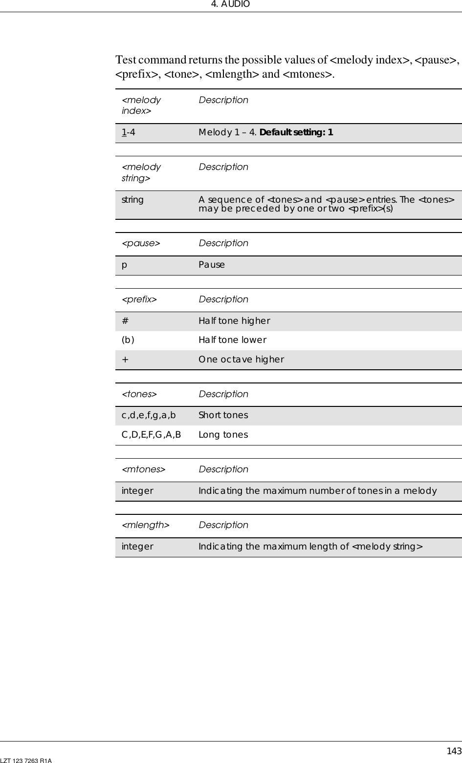
![GM47/GM48 INTEGRATOR’S MANUAL140 LZT 123 7263 R1A4.13 AT*ERIN Ericsson Ring SetUsed to set sound for incoming voice, line L1 and L2, fax, data calls andalarm. For each of the incoming call types and alarm: voice on line 1,voice on line 2, fax calls and data calls and alarm a sound type isselected.The type of sound is either a ring signal, selected from a predefined set,a melody, selected from a predefined set, or an own melody, selectedfrom a set specified by the user.Line 1 is the default for <call type> if the parameter is not given.<place> Description0Hand held1Car mountedDescription Command Possible ResponsesSets ring type forincoming voice (L1and L2), fax and datacalls and alarmAT*ERIN=<sound type>,[<call type>]•+CMEERROR:<err>•OK•ERRORRead the settings ofring type and volumefor the call typesAT*ERIN? •*ERIN:<soundtype1>,<call type1>[<CR><LF>…*ERIN:<sound typen>,<call type n>]•+CMEERROR:<err>•OK•ERRORTest if the command issupported AT*ERIN=? •*ERIN:listofsupported <soundtype>s, list ofsupported <calltype>s•+CMEERROR:<err>•OK•ERROR<call type> Description1Line 12Line 23Fax4Data5Alarm](https://usermanual.wiki/Sony/6220501-BV.Exhibit-8-Integrators-Manual/User-Guide-247869-Page-140.png)
![GM47/GM48 INTEGRATOR’S MANUAL142 LZT 123 7263 R1A4.15 AT*ESMA Ericsson Set Message Alert Sound4.16 AT*ESOM Ericsson Settings Own MelodySets the user defined own melodies in the MS. The <prefix> and <tone>indicates together the tone frequency and duration. The <pause> sets apause between tones.Description Command Possible ResponsesSets the answer modesettings in the MS AT*ESAM=<mode> •+CMEERROR:<err>•OK•ERRORRead the currentsetting AT*ESAM? •*ESAM:<mode>•+CMEERROR:<err>•OK•ERRORTest if the command issupported AT*ESAM=? •*ESAM:listofsupported <mode>s•+CMEERROR:<err>•OK•ERROR<mode > Description0Answer mode is not set to “Any key”, or “Auto” (off)1Any Key mode on2Auto mode onDescription Command Possible ResponsesSets the ownmelodies in theMSAT*ESOM=[<melody index>],<melody string>•+CME ERROR: <err>•OK•ERRORShows thecurrent settings,i.e. the currentlystored melodiesAT*ESOM? • *ESOM: <melody index>,<melody string 1>, <CR><LF>……*ESOM: <melody index>,<melody string n>•+CMEERROR:<err>•OK•ERRORShows if thecommand issupportedAT*ESOM=? • *ESOM: (list of supported<melody index>),(list ofsupported <pause>s),(list ofsupported <prefix>s),(list ofsupported <tone>s),<mlength>,<mtones>•+CMEERROR:<err>•OK•ERROR](https://usermanual.wiki/Sony/6220501-BV.Exhibit-8-Integrators-Manual/User-Guide-247869-Page-142.png)
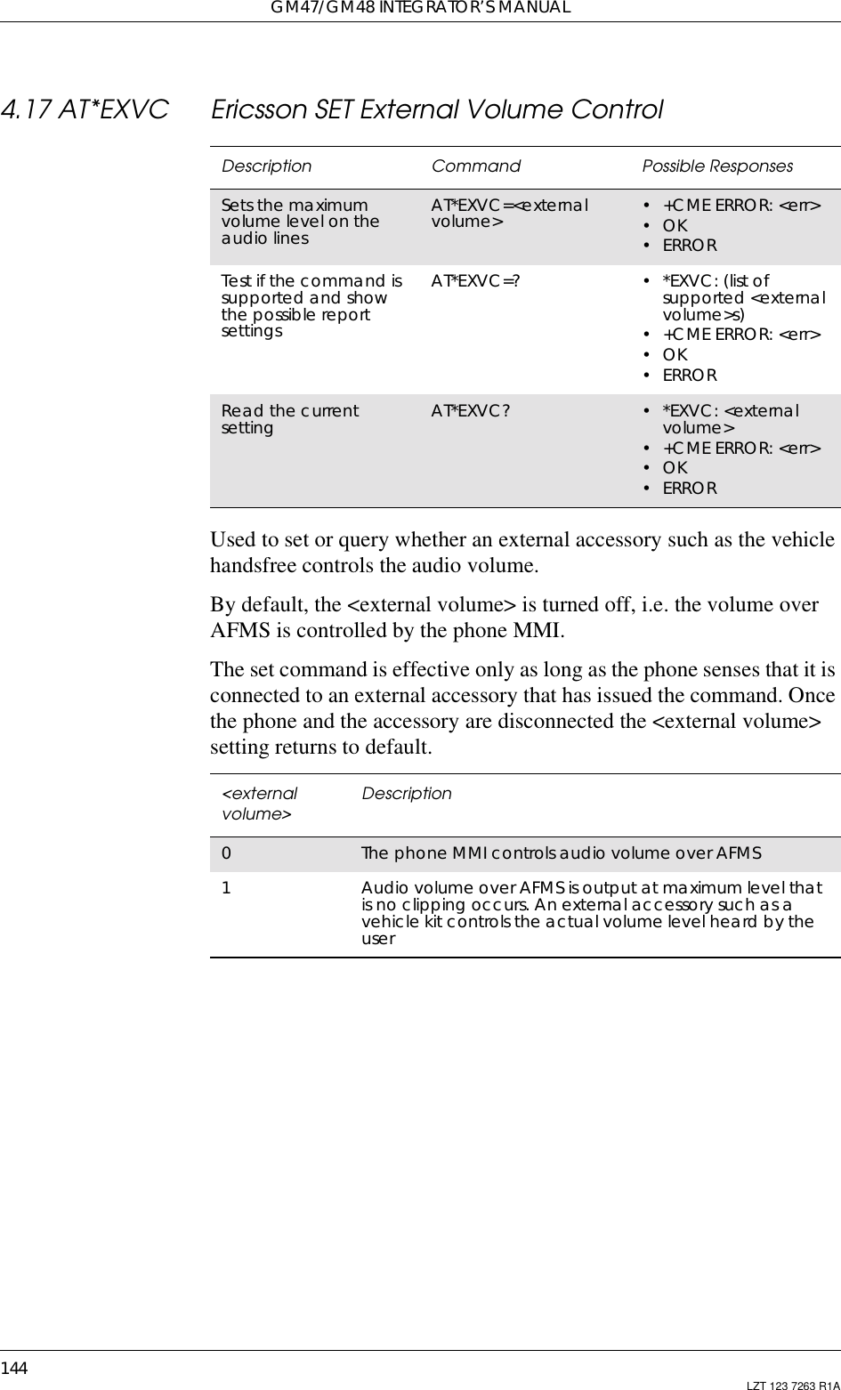
![4. AUDIO145LZT 123 7263 R1A4.18 ATM Monitor Speaker ControlDefine the activity of the speaker. This command is ignored by themodem and is only included for compatibility.Description Syntax Possible ResponsesSet monitor speakercontrol ATM[=][<speaker>] •OK•ERRORRead the currentsetting ATM? M: <speaker>Show if the commandis supported ATM=? M: (list of supported<speaker>s)<speaker> Description0Off during the entire call. Default value1-3 Different “on” modes](https://usermanual.wiki/Sony/6220501-BV.Exhibit-8-Integrators-Manual/User-Guide-247869-Page-145.png)

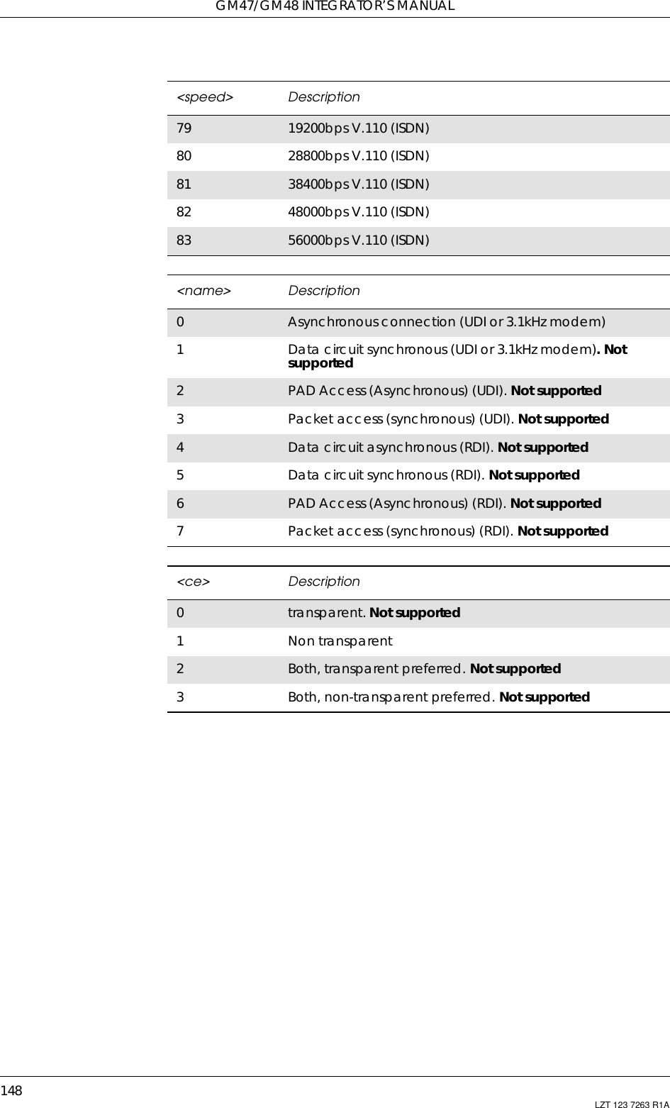
![147LZT 123 7263 R1A5. Data - CSD/HSCSD5.1 AT+CBST Select Bearer Service TypeSelects the bearer service <name> with data rate <speed>, and theconnection element <ce> to be used when data calls are originated.Values may also be used during mobile terminated data call setup,especially in the case of single numbering scheme calls.Test command returns values supported by the TA as compound values.Description Command Possible ResponsesSelect bearer servicetype AT+CBST=[<speed>,[<name>,[<ce>]]] •OK•ERRORRead the command AT+CBST? •+CBST:<speed>,<name>,<ce>•OK•ERRORTest if the command issupported AT+CBST=? •+CBST:(listofsupported<speed>s,list ofsupported<name>s,list of supported<ce>s)•OK•ERROR<speed> Description0Auto selection of baud rate42400bps V.22bis64800bps V.3279600bps V.3212 9600bps V.3414 14400bps V.3415 19200bps V.3416 28800bps V.3468 2400bps V.110 (ISDN)70 4800bps V.110 (ISDN)71 9600bps V.110 (ISDN)75 14400bps V.110 (ISDN)](https://usermanual.wiki/Sony/6220501-BV.Exhibit-8-Integrators-Manual/User-Guide-247869-Page-147.png)
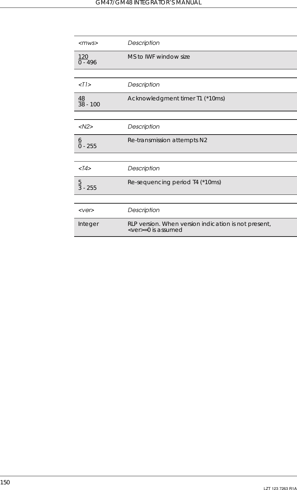
![5. DATA - CSD/HSCSD149LZT 123 7263 R1A5.2 AT+CRLP Radio Link ProtocolRadio link protocol (RLP) parameters used when non-transparent datacalls are originated may be altered with this command. Availablecommand subparameters depend on the RLP versions implemented bythe device (e.g. <ver> may not be available if device supports onlyversions 0 and 1).Note! If radio link protocol is not used, but some other error correctingprotocol (for transparent data calls), V.25ter [4] Error Control Selectiontest command +ES=? may be used to indicate the presence of theprotocol.Read command returns current settings for each supported RLP version<verx>. Only RLP parameters applicable to the corresponding <verx>are returned.Test command returns values supported by the TA as a compoundvalue. If ME/TA supports several RLP versions <verx>, the RLPparameter value ranges for each <verx> are returned in a separate line.Description Command Possible ResponsesSet radio linkprotocol AT+CRLP=[<iws>[,<mws>[,<T1>[,<N2>[,<ver>[, <T4>]]]]]]•OK•ERRORRead thecommand AT+CRLP? •+CRLP:<iws>,<mws>,<T1>,<N2>[,<ver1>[,<T4>]][<CR><LF>•+CRLP:<iws>,<mws>,<T1>,<N2>[,<ver2>[,<T4>]][...]]•OK•ERRORTest if thecommand issupportedAT+CRLP=? • +CRLP: (list of supported <iws>s),(list of supported <mws>s),(list of supported <T1>s),(list of supported<N2>s)[,<ver1>[,(list of supported <T4>s)]][<CR><LF>+CRLP: (list ofsupported <iws>s), (list ofsupported <mws>s), (list ofsupported <T1>s), (list ofsupported <N2>s)[,<ver2>[,(listofsupported <T4>s)]][...]]•OK•ERROR<iws> Description1200 - 496 IWF to MS window size](https://usermanual.wiki/Sony/6220501-BV.Exhibit-8-Integrators-Manual/User-Guide-247869-Page-149.png)
![151LZT 123 7263 R1A6. Data - GPRS6.1 AT+CGACT PDP Context Activate or DeactivateUsed to activate or deactivate the specified PDP context(s).After the command has completed, the MS remains in V.250 commandstate. If the MS is already in the requested state, the command is ignoredand OK is returned. If the requested state cannot be achieved, ERRORor +CME: ERROR is returned. If the MS is not attached to the GPRSservice when the activation form of the command is executed, the MSfirst performs a GPRS attach and then attempts to activate the specificcontexts.If no <cid>s are specified the activation form of the command activatesall defined contexts.If no <cid>s are specified the deactivation form of the commanddeactivates all active contexts.Description Command Possible ResponsesActivate or deactivatethe specified PDPcontext(s)+CGACT=[<state>[,<cid>[,<cid>[,…]]]] •+CMEERROR:<err>•OK•ERRORRead the command +CGACT? • +CGACT: <cid>,<state>[<CR><LF>+CGACT: <cid>,<state>[...]]•OK•ERRORTest if the command issupported +CGACT=? •+CGACT:(listofsupported <state>s)•OK•ERROR<state> Description0PDP context activation deactivated1PDP context activation activated<cid> DescriptionInteger type A numeric parameter which specifies a specific PDPcontext definition](https://usermanual.wiki/Sony/6220501-BV.Exhibit-8-Integrators-Manual/User-Guide-247869-Page-151.png)
![GM47/GM48 INTEGRATOR’S MANUAL152 LZT 123 7263 R1A6.2 AT+CGATT GPRS Attach or DetachUsed to attach the MS to, or detach the MS from, the GPRS/packetdomain service. After the command has completed, the MS remains inV.250 command state. If the MS is already in the requested state, thecommand is ignored and the OK response is returned. If the requestedstate cannot be achieved, an ERROR or +CME ERROR response isreturned. Extended error responses (enabled by the +CMEE command)are listed in subclause 1.2.3.Any active PDP contexts will be automatically deactivated when theattachment state changes to detached.Note! This command has the characteristics of both the V.250 action andparameter commands. Hence it has the read form in addition to theexecution/set and test forms.Description Command Possible ResponsesAttach or detach MSto the GPRS/packetdomain/packetdomain service+CGATT=[<state>] •+CMEERROR:<err>•OK•ERRORRead the command +CGATT? • +CGATT: <state>•OK•ERRORTest if the command issupported +CGATT=? • +CGATT: (list ofsupported <state>s)•OK•ERROR<state> Description0Detached1Attached](https://usermanual.wiki/Sony/6220501-BV.Exhibit-8-Integrators-Manual/User-Guide-247869-Page-152.png)
![6. DATA - GPRS153LZT 123 7263 R1A6.3 AT+CGDATA Enter Data StateCauses the MS to perform whatever actions are necessary to establishcommunication between the TE and the network using one or moreGPRS/packet domain PDP types. This may include performing aGPRS/packet domain attach and one or more PDP context activations.Description Command Possible ResponsesEstablish GPRS/packetdomain connection +CGDATA=[<L2p>,[cid[,cid>[,…]]]] •CONNECT•ERROR•OK•ERRORTest if the command issupported +CGDATA=? •+CGDATA:(listofsupported <L2P>s)•OK•ERROR<L2P> DescriptionPPP Point-to-point protocol for a PDP such as IPM-xxxx Manufacturer specific protocol (xxx is an alphanumericstring)](https://usermanual.wiki/Sony/6220501-BV.Exhibit-8-Integrators-Manual/User-Guide-247869-Page-153.png)
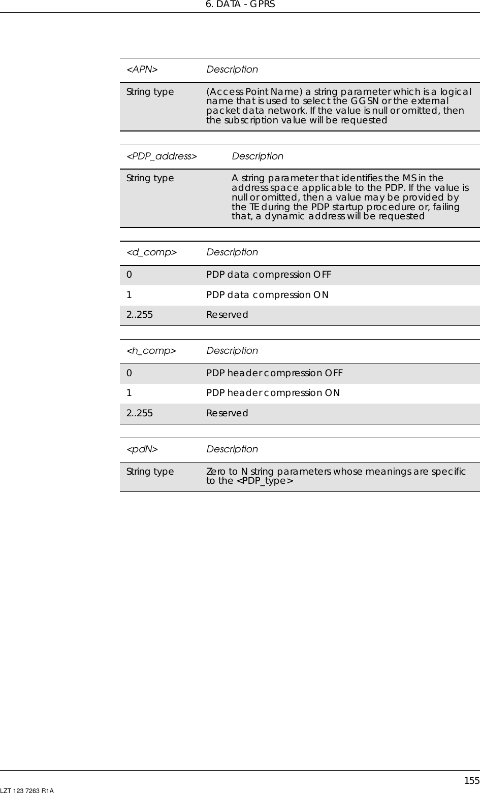
![GM47/GM48 INTEGRATOR’S MANUAL154 LZT 123 7263 R1A6.4 AT+CGDCONT Define PDP ContextSpecifies PDP context parameter values for a PDP context identified bythe (local) context identification parameter, <cid>.Description Command Possible ResponsesSelect PDPcontextparameters+CGDCONT=[<cid>[,<PDP_type> [,<APN>[,<PDP_addr>[,<d_comp>[,<h_comp> [,<pd1>[,…[,pdN]]]]]]]]]• +CME ERROR: <err>•OK• ERRORRead thecommand +CGDCONT? • +CGDCONT: <cid>,<PDP_type>,<APN>,<PDP_addr>,<d_comp>,<h_comp>[,<pd1>[,…[,pdN]]][<CR><LF>+CGDCONT:<cid>, <PDP_type>,<APN>,<PDP_addr>,<d_comp>,<h_comp>[,<pd1>[,…[,pdN]]][...]]•OK• ERRORTest if thecommand issupported+CGDCONT=? •+CGDCONT:(rangeofsupported <cid>s),<PDP_type>,,,(list ofsupported <d_comp>s),(list of supported <h_comp>s)[,(list of supported <pd1>s)[,…[,(list of supported<pdN>s)]]][<CR><LF>+CGDCONT:(range of supported <cid>s),<PDP_type>,,,(list ofsupported <d_comp>s),(list of supported <h_comp>s)[,(list of supported<pd1>s)[,…[,(list of supported<pdN>s)]]] [...]]•OK• ERROR<cid> DescriptionInteger type (PDP Context Identifier) a numeric parameter whichspecifies a particular PDP context definition. Theparameter is local to the TE-MS interface and is used inother PDP context-related commands. The range ofpermitted values (minimum value = 1) is returned by thetest form of the command1-10 Supported values. Ericsson specific<PDP_type> DescriptionX25 ITU-T/CCITT X.25 layer 3. Not supportedIP Internet Protocol (IETF STD 5)OSPIH Internet Hosted Octet Stream Protocol. Not supportedPPP Point to Point Protocol (IETF STD 51). Not supported](https://usermanual.wiki/Sony/6220501-BV.Exhibit-8-Integrators-Manual/User-Guide-247869-Page-154.png)
![GM47/GM48 INTEGRATOR’S MANUAL156 LZT 123 7263 R1A6.5 AT+CGEREP GPRS Event ReportingEnables or disables the sending of unsolicited result codes, +CGEV:XXX from MS to TE in the case of certain events occurring in theGPRS/packet domain MS or the network.Description Command Possible ResponsesSet command +CGEREP=[<mode>[,<bfr>]] •+CMEERROR:<err>•OK•ERRORRead the command +CGEREP? • +CGEREP:<mode>,<bfr>•OK•ERRORTest if the command issupported +CGEREP=? • +CGEREP: (list ofsupported<mode>s),(list ofsupported <bfr>s)•OK•ERROR<mode> Description0Buffer unsolicited result codes in the MS. No codes areforwarded to the TE1Discard unsolicited result codes when MS-TE link isreserved; otherwise forward them directly to the TE<bfr> Description0MS buffer of unsolicited result codes defined within thiscommand is cleared when <mode> 1 or 2 is entered](https://usermanual.wiki/Sony/6220501-BV.Exhibit-8-Integrators-Manual/User-Guide-247869-Page-156.png)
![6. DATA - GPRS157LZT 123 7263 R1A6.6 AT+CGPADDR Show PDP AddressReturns a list of PDP addresses for the specified context identifiers. Thetest command returns a list of defined <cid>s.Description Command Possible ResponsesShow PDP addressesfor specified CIDs +CGPADDR=[<cid>[,<cid> [,…]]] • +CGPADDR:<cid>,<PDP_addr>[<CR><LF>+CGPADDR:<cid>,<PDP_addr>[...]]•OK•ERRORTest if the command issupported +CGPADDR=? • +CGPADDR: (list ofdefined <cid>s)•OK•ERROR<cid> DescriptionInteger type Parameter which specifies a particular PDP contextdefinition (see +CGDCONT command). If no <cid> isspecified, the addresses for all defined contexts arereturned<PDP_address> DescriptionString type A string that identifies the MS in the address spaceapplicable to the PDP. The address may be static ordynamic. For a static address, it will be the one set bythe +CGDCONT and +CGDSCONT commands whenthe context was defined. For a dynamic address it willbe the one assigned during the last PDP contextactivation that used the context definition referred toby <cid>. <PDP_address> is omitted if none is available](https://usermanual.wiki/Sony/6220501-BV.Exhibit-8-Integrators-Manual/User-Guide-247869-Page-157.png)
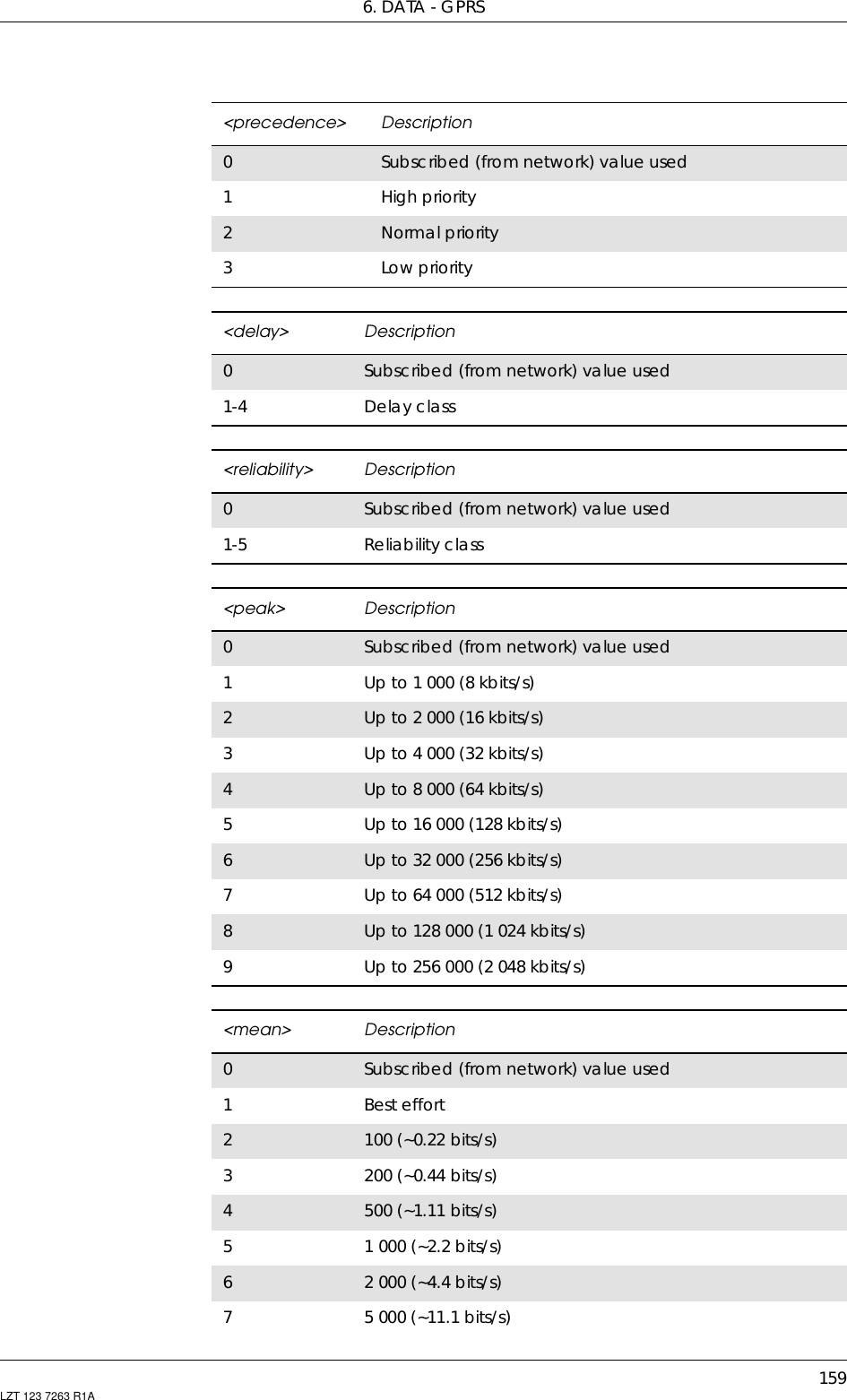
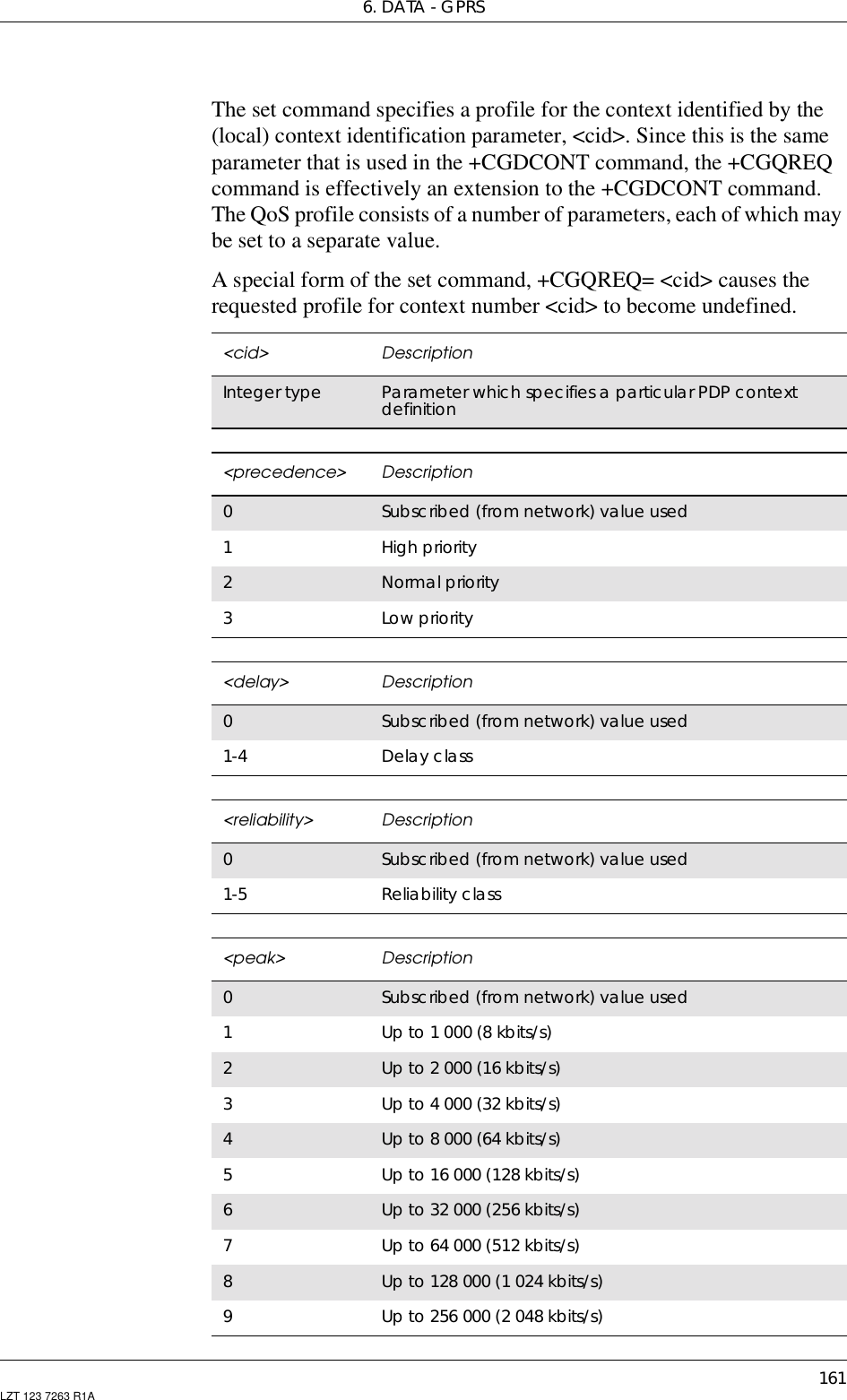
![GM47/GM48 INTEGRATOR’S MANUAL158 LZT 123 7263 R1A6.7 AT+CGQMIN Quality of Service Profile (Minimum Acceptable)Allows the TE to specify a minimum acceptable profile which ischecked by the MS against the negotiated profile returned in theActivate PDP Context Accept message.The set command specifies a profile for the context identified by the(local) context identification parameter, <cid>. Since this is the sameparameter that is used in the +CGDCONT command, the +CGQMINcommand is effectively an extension to the +CGDCONT command.The QoS profile consists of a number of parameters, each of which maybe set to a separate value.A special form of the set command, +CGQMIN= <cid> causes theminimum acceptable profile for context number <cid> to becomeundefined. In this case no check is made against the negotiated profile.Description Command Possible ResponsesSet minimumacceptableprofile+CGQMIN=[<cid>[,<precedence>[,<delay> [,<reliability>[,<peak>[,<mean>]]]]]]•+CMEERROR:<err>•OK•ERRORRead thecommand +CGQMIN? •+CGQMIN:<cid>,<precedence>, <delay>,<reliability>, <peak>,<mean>[<CR><LF>+CGQMIN:<cid>, <precedence>,<delay>, <reliability>, <peak>,<mean>[…]]•OK•ERRORTest if thecommand issupported+CGQMIN=? • +CGQMIN:<PDP_type>,(listofsupported <precedence>s),(list of supported <delay>s),(list of supported <reliability>s), (list of supported <peak>s),(list of supported<mean>s)[<CR><LF>+CGQMIN: <PDP_type>, (list ofsupported <precedence>s),(list of supported <delay>s),(list of supported <reliability>s), (list of supported <peak>s),(list of supported<mean>s)[…]]•OK•ERROR<cid> DescriptionInteger type Parameter which specifies a particular PDP contextdefinition](https://usermanual.wiki/Sony/6220501-BV.Exhibit-8-Integrators-Manual/User-Guide-247869-Page-158.png)
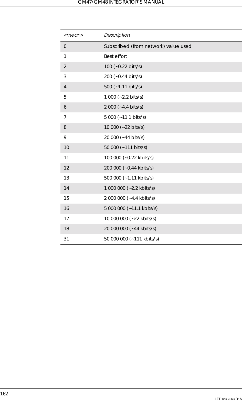
![GM47/GM48 INTEGRATOR’S MANUAL160 LZT 123 7263 R1A6.8 AT+CGQREQ Quality of Service Profile (Requested)Allows the TE to specify a quality of service profile that is used whenthe MS sends an activate PDP context request message to the network.810 000 (~22 bits/s)920 000 (~44 bits/s)10 50 000 (~111 bits/s)11 100 000 (~0.22 kbits/s)12 200 000 (~0.44 kbits/s)13 500 000 (~1.11 kbits/s)14 1 000 000 (~2.2 kbits/s)15 2 000 000 (~4.4 kbits/s)16 5 000 000 (~11.1 kbits/s)17 10 000 000 (~22 kbits/s)18 20 000 000 (~44 kbits/s)31 50 000 000 (~111 kbits/s)<mean> DescriptionDescription Command Possible ResponsesSet qualityof serviceprofile+CGQREQ=[<cid>[,<precedence>[,<delay>[,<reliability>[,<peak>[,<mean>]]]]]]•+CMEERROR:<err>•OK•ERRORRead thecommand +CGQREQ? • +CGQREQ: <cid>, <precedence>,<delay>, <reliability>, <peak>,<mean>[<CR><LF>+CGQREQ:<cid>, <precedence>, <delay>,<reliability>, <peak>, <mean>[…]]•OK•ERRORTest if thecommandis supported+CGQREQ=? • +CGQREQ: <PDP_type>,(list of supported <precedence>s),(list of supported <delay>s),(list of supported <reliability>s),(list of supported <peak>s),(list of supported <mean>s)[<CR><LF>+CGQREQ: <PDP_type>,(list of supported <precedence>s),(list of supported <delay>s),(list of supported <reliability>s),(list of supported <peak>s),(list of supported <mean>s)[…]]•OK•ERROR](https://usermanual.wiki/Sony/6220501-BV.Exhibit-8-Integrators-Manual/User-Guide-247869-Page-160.png)
![6. DATA - GPRS163LZT 123 7263 R1A6.9 AT+CGREG GPRS Network Registration StatusControls the presentation of an unsolicited result code +CGREG: <stat>when <n>=1 and there is a change in the GPRS/packet domain networkregistration status of the MS, or code +CGREG: <stat>[,<lac>,<ci>]when <n>=2 and there is a change of the network cell.Note! If the GPRS/Packet Domain MS also supports circuit mode services, the+CGREG command and +CGREG: result code apply to the registrationstatus and location information for those services.Description Command Possible ResponsesSet command AT+CGREG=[<n>] •+CMEERROR:<err>•OK•ERRORRead the currentsettings AT+CGREG? •+CGREG:<n>,<stat>[,<lac>,<ci>]•+CMEERROR:<err>•OK•ERRORTest if the command issupported AT+CGREG=? •+CGREG:(listofsupported <n>s)•OK•ERROR<n> Description0Disable network registration unsolicited result code1Enable network registration unsolicited result code2Enable network registration and location informationunsolicited result code<stat> Description0Notregistered,MSisnotsearchingforanewoperatortoregister with1Registered, home network2Not registered, but MS is searching for a new operator toregister with3Registration denied4Unknown5Registered, roaming<lac> DescriptionString type Two byte location area code in hexadecimal format](https://usermanual.wiki/Sony/6220501-BV.Exhibit-8-Integrators-Manual/User-Guide-247869-Page-163.png)
![GM47/GM48 INTEGRATOR’S MANUAL164 LZT 123 7263 R1A6.10 AT+CGSMS Select Service for MO SMS MessagesUsed to specify the service or service preference that the MS will use tosend MO SMS messages. The read command returns the currentlyselected service or service preference.<ci> DescriptionString type Two byte cell ID in hexadecimal formatDescription Command Possible ResponsesSet service or servicepreference +CGSMS=[<service>] •OK•ERRORRead the command +CGSMS? • +CGSMS: <service>•OK•ERRORTest if the command issupported +CGSMS=? • +CGSMS: (list ofavailable<service>s)•OK•ERROR<services> Description0GPRS/packet domain1Circuit switched2GPRS/packet domain preferred (use circuit switched ifGPRS/packet domain not available)3Circuit switched preferred (use GPRS/packet domain ifcircuit switched not available)](https://usermanual.wiki/Sony/6220501-BV.Exhibit-8-Integrators-Manual/User-Guide-247869-Page-164.png)
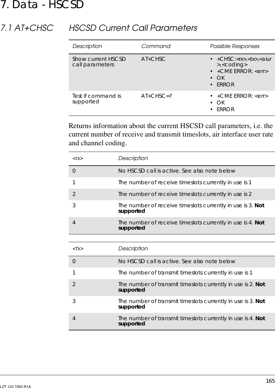
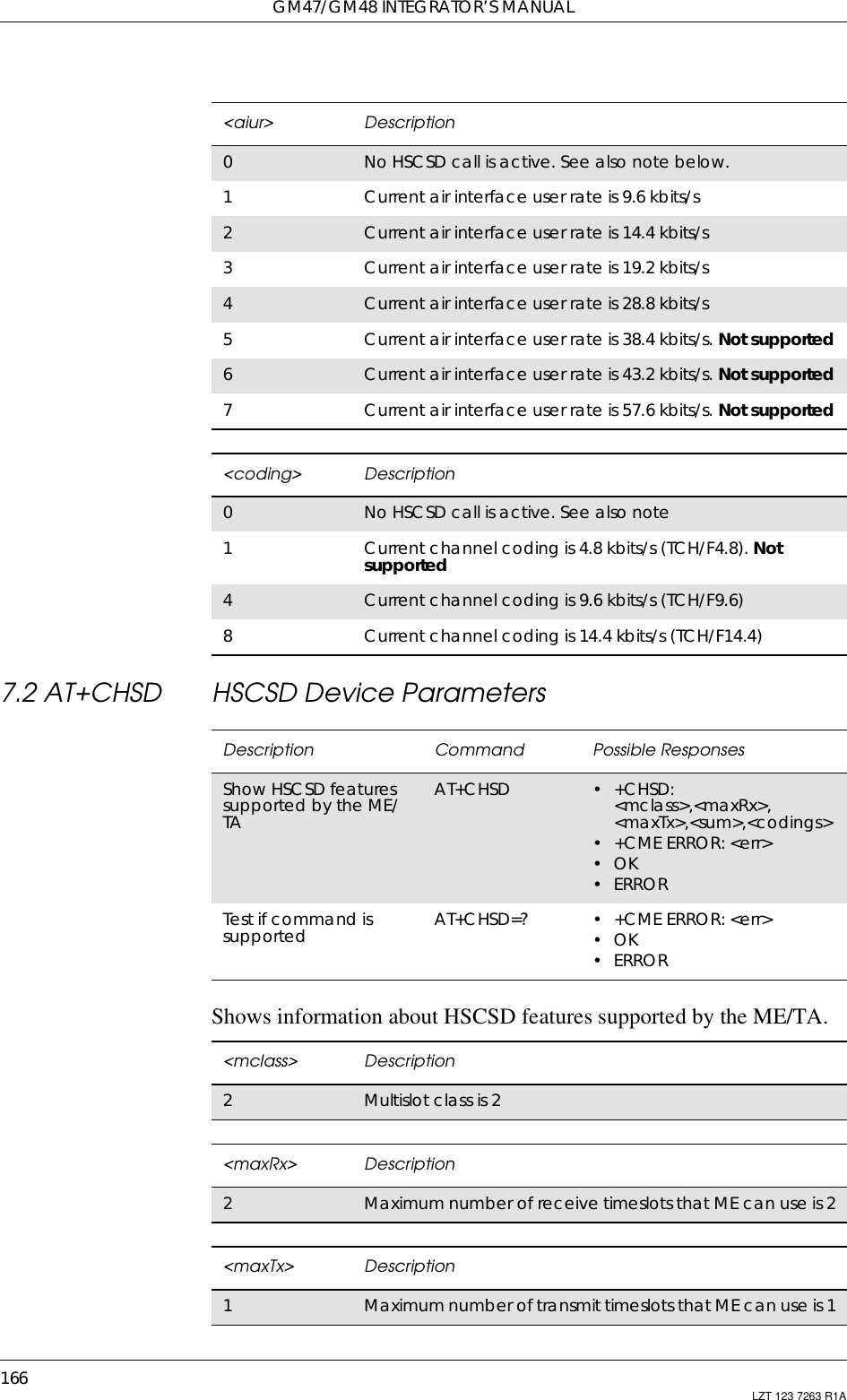
![7. DATA - HSCSD167LZT 123 7263 R1A7.3 AT+CHSN HSCSD Non Transparent Call ConfigurationControls parameters for non-transparent HSCSD calls. Changing<topRx> or <codings> during a call does not affect the current call.Changing <wAiur> or <wRx> affects the current call only if <topRx>was non-zero when the call was established. When using the command<sum> Description3Total number of receive and transmit timeslots that MEcanuseatthesametimeis3(i.e.2+1).Thefollowingapplies in a HSCSD call: 2 (receive slots) + (transmit slots)<sum><codings> Description1Indicates that the accepted channel coding for the nextestablished non-transparent HSCSD call is 4.8 kbits/s only.Not supported4Indicates that the accepted channel coding for the nextestablished non-transparent HSCSD call is 9.6 kbits/s only5Indicates that the accepted channel codings for the nextestablished non-transparent HSCSD call are both 4.8 kbits/sand9.6kbits/s.Not supported8Indicates that the accepted channel coding for the nextestablished non-transparent HSCSD call is 14.4 kbits/s only12 Indicates that the accepted channel codings for the nextestablished non-transparent HSCSD call are both 9.6 kbits/sand14.4kbits/sDescription Command Possible ResponsesSet HSCSDconfiguration. Thiscommand is also usedduring a call if new<wAiur> and/or <wRx>are/is desiredAT+CHSN=[<wAiur>[,<wRx>[,<topRx>[,<codings>]]]]•+CMEERROR:<err>•OK•ERRORShow current non-transparent HSCSDsettingAT+CHSN? •+CHSN:<wAiur>,<wRx>, <topRx>,<codings>•+CMEERROR:<err>•OK•ERRORTest if command issupported and showparameter rangesAT+CHSN=? •+CHSN:(listofsupported<wAiur>s), (list ofsupported <wRx>s),(list of supported<topRx>s), (list ofsupported<codings>s)•+CMEERROR:<err>•OK•ERROR](https://usermanual.wiki/Sony/6220501-BV.Exhibit-8-Integrators-Manual/User-Guide-247869-Page-167.png)
![GM47/GM48 INTEGRATOR’S MANUAL168 LZT 123 7263 R1Ain this way it comes in the “action” command category. This is what isreferred to as user initiated up- and down-grading in GSM 02.34 [4]and GSM 03.34 [7].Note! Recommended value for parameter <speed> in AT+CBST [11] is 0.<wAiur> Description0TA/ME shall calculate a proper number of receivetimeslots from currently selected fixed network user rate(<speed> parameter from +CBST command, ref [11]) and<codings>, and <wRx> (or <maxRx> from +CHSDcommand if <wRx>=0) See note below.1Wanted air interface user rate is 9.6 kbit/s2Wanted air interface user rate is 14.4 kbit/s3Wanted air interface user rate is 19.2 kbit/s4Wanted air interface user rate is 28.8 kbit/s5Wanted air interface user rate is 38.4 kbit/s. Not supported6Wanted air interface user rate is 43.2 kbit/s. Not supported7Wanted air interface user rate is 57.6 kbit/s. Not supported<wRx> Description0TA/ME shall calculate a proper number of receivetimeslots from currently selected <wAiur> and <codings>Seenotebelow1Wanted number of receive timeslots is 12Wanted number of receive timeslots is 23Wanted number of receive timeslots is 3. Not supported4Wanted number of receive timeslots is 4. Not supported<topRx> Description0Indicates that the user is not going to change <wAiur>and /or <wRx> during the next call1Top value for <wRx> that user is going to request duringthe next established non-transparent HSCSD call is 12Top value for <wRx> that user is going to request duringthe next established non-transparent HSCSD call is 23Top value for <wRx> that user is going to request duringthe next established non-transparent HSCSD call is 3. Notsupported4Top value for <wRx> that user is going to request duringthe next established non-transparent HSCSD call is 4. Notsupported](https://usermanual.wiki/Sony/6220501-BV.Exhibit-8-Integrators-Manual/User-Guide-247869-Page-168.png)
![7. DATA - HSCSD169LZT 123 7263 R1A7.4 AT+CHSR HSCSD Parameters ReportSets the HSCSD parameter reporting on or off. If enabled, theintermediate result code +CHSR is activated.<codings> Description1Indicates that the accepted channel coding for the nextestablished non-transparent HSCSD call is 4.8 kbit/s only.Not supported4Indicates that the accepted channel coding for the nextestablished non-transparent HSCSD call is 9.6 kbit/s only5Indicates that the accepted channel codings for the nextestablished non-transparent HSCSD call are both 4.8 kbit/sand 9.6 kbit/s. Not supported8Indicates that the accepted channel coding for the nextestablished non-transparent HSCSD call is 14.4 kbit/s only12 Indicates that the accepted channel codings for the nextestablished non-transparent HSCSD call are both 9.6 kbit/sand 14.4 kbit/sDescription Command Possible ResponsesSet HSCSD parametersreporting on or off AT+CHSR=[<mode>] •+CMEERROR:<err>•OK•ERRORShow current setting AT+CHSR? •+CHSR:<mode>•+CMEERROR:<err>•OK•ERRORTest if command issupported and showparameter rangeAT+CHSR=? •+CHSR: (list ofsupported<modes>s)•+CMEERROR:<err>•OK•ERROR<mode> Description0Disable reporting1Enable reporting](https://usermanual.wiki/Sony/6220501-BV.Exhibit-8-Integrators-Manual/User-Guide-247869-Page-169.png)
![GM47/GM48 INTEGRATOR’S MANUAL170 LZT 123 7263 R1A7.5 AT+CHSU HSCSD Automatic User Initiated UpgradingEnables or disables the HSCSD automatic user-initiated upgrade.Description Command Possible ResponsesSet HSCSD automaticuser initiatedupgrading on or offAT+CHSU=[<mode>] •OK•ERRORShow current setting AT+CHSU? •+CHSU=<mode>•OK•ERRORTest if command issupported and showparameter rangeAT+CHSU=? •+CHSU:(listofsupported<modes>s)•OK•ERROR<mode> Description0Disable use of UP bit for upgrading1Enable use of UP bit for upgrading](https://usermanual.wiki/Sony/6220501-BV.Exhibit-8-Integrators-Manual/User-Guide-247869-Page-170.png)
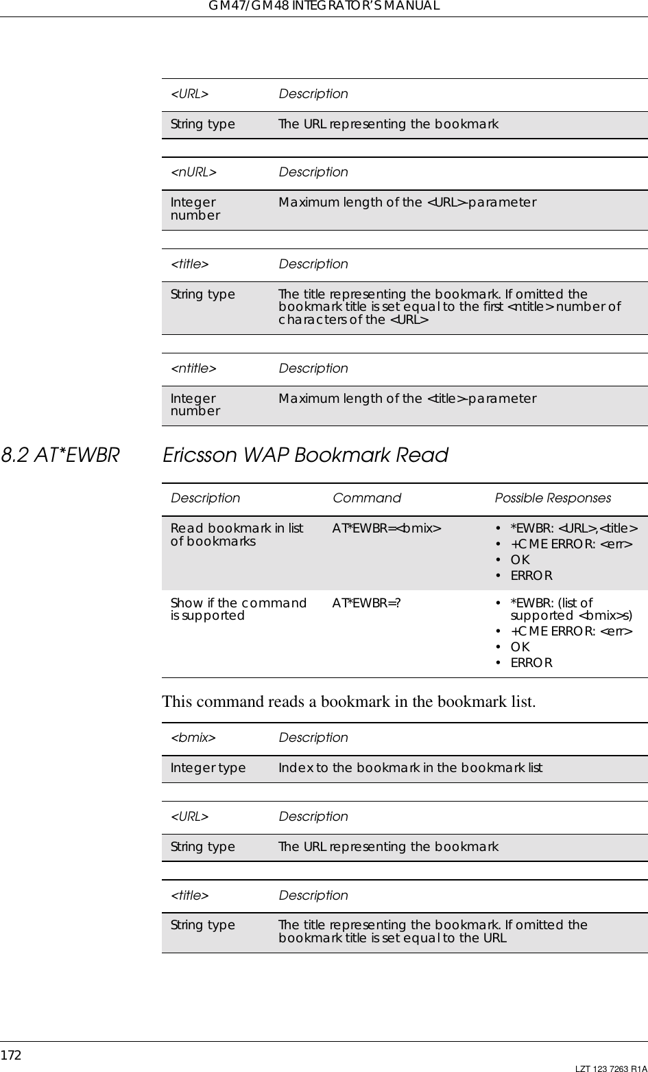
![171LZT 123 7263 R1A8. Data - WAP8.1 AT*EWBA Ericsson WAP Bookmark AddThis command adds or deletes a bookmark in the list of bookmarks.To add a bookmark the <bmix> parameter should be set to 0. Thebookmark is always added to the last position of the bookmark list.If the <title> parameter is omitted the bookmark title is set to the first<ntitle> number of characters of the <URL>.If the <URL> parameter exceeds <nURL> number of characters, thebookmark URL is truncated to the last ‘/’ character among the last<nURL> number of characters.To delete a bookmark from the list, the <bmix> parameter should be setto a value greater than 0. The <URL> and the <title> parameters mustbe omitted.Description Command Possible ResponsesAdd or deleteabookmarkinthe list ofbookmarksAT*EWBA=<bmix>[,<URL>[,<title>]] • +CME ERROR: <err>•OK•ERRORList content ofbookmark list AT*EWBA? •*EWBA:<bmix1>,<URL1>,<title1>[<CR><LF>*EWBA:<bmix2>,<URL2>,<title2>[…]]• +CME ERROR: <err>•OK•ERRORShow if thecommand issupported.AT*EWBA=? • *EWBA: (list of supported<bmix>s),<nURL>,<ntitle>• +CME ERROR: <err>•OK•ERROR<bmix> Description0Add the bookmark to the last position in the list ofbookmarks. This value is only valid for adding bookmarks1Reserved. The index 1 is reserved for the bookmark toEricssonMobileInternetandshouldnotbealteredordeleted2..25 Index to list of bookmarks. These values are only valid fordeleting bookmarks](https://usermanual.wiki/Sony/6220501-BV.Exhibit-8-Integrators-Manual/User-Guide-247869-Page-171.png)
![8. DATA - WAP173LZT 123 7263 R1A8.3 AT*EWCG Ericsson WAP CSD GatewaySets the primary and secondary gateways for the WAP browser usedwhen CSD is the preferred bearer. The gateways are either an IP addressor a URL on the network where the gateway can be reached.Description Command Possible ResponsesSet primary andsecondary WAPgatewayAT*EWCG=<primsec>,<gateway> •+CMEERROR:<err>•OK•ERRORRead primaryand secondaryWAP gatewayAT*EWCG? •*EWCG:<primsec1>,<gateway1>[<CR><LF>*EWCG:<primsec2>,<gateway2>]•+CMEERROR:<err>•OK•ERRORShow if thecommand issupportedAT*EWCG=? • *EWCG: (list of supported<primsec>s),<ngateway>•+CMEERROR:<err>•OK•ERROR<primsec> Description1Set primary gateway2Set secondary gateway. Not supported<gateway> DescriptionString type Gateway address<ngateway> DescriptionInteger type Maximum length of gateway address](https://usermanual.wiki/Sony/6220501-BV.Exhibit-8-Integrators-Manual/User-Guide-247869-Page-173.png)
![8. DATA - WAP177LZT 123 7263 R1A8.9 AT*EWPA Ericsson WAP Push Access SettingThe command is used to decide if message push is allowed.8.10 AT*EWPB Ericsson WAP Preferred BearerThis command sets the preferred bearer for WAP. If Internet account ischosen as the preferred bearer, the index of the Internet account to beused shall be sent as the second parameter: <IA_index>. If SMS ischosen as the preferred bearer a second parameter is ignored.Description Command Possible ResponsesSets the push access AT*EWPA=<onoff> •OK• +CME ERROR <err>Reads the currentsettings AT*EWPA? *EWPA: <onoff>Tests if the command issupported AT*EWPA=? •*EWPA:(listofsupported <onoff>s)• +CME ERROR <err><onoff> Description0Always ask1Message push disabled2Message push enabledDescription Command Possible ResponsesSet preferred WAPcarrier AT*EWPB=<pbearer>[,<IA_index>] •+CMEERROR:<err>•OK•ERRORRead preferred WAPcarrier AT*EWPB? •*EWPB:<pbearer>[,<IA_index>]•+CMEERROR:<err>•OK•ERRORShow if the commandis supported AT*EWPB=? •*EWPB:(listofsupported<pbearer>s),(list ofsupported<IA_index>s)•+CMEERROR:<err>•OK•ERROR<pbearer> Description1SMS2Not supported3Internet account](https://usermanual.wiki/Sony/6220501-BV.Exhibit-8-Integrators-Manual/User-Guide-247869-Page-177.png)
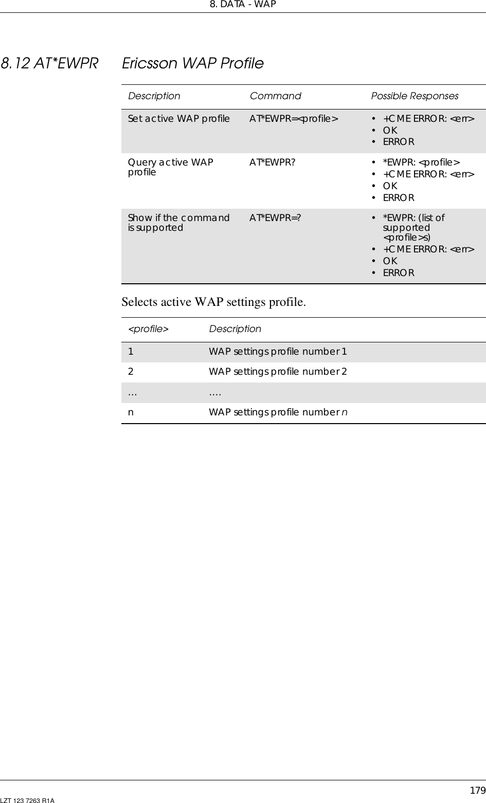
![GM47/GM48 INTEGRATOR’S MANUAL178 LZT 123 7263 R1A8.11 AT*EWPN Ericsson WAP Profile NameSets the name of the profile defined by <profile>.<IA_index> Description0Always ask1–65000 Index of Internet account to be used by the WAP browserDescription Command Possible ResponsesSet WAP profilename AT*EWPN=<profile>,<name> • +CME ERROR: <err>•OK• ERRORList WAP profilenames AT*EWPN? • *EWPN: <profile1>,<name1>,<lock_state>[<CR><LF>*EWPN: <profile2>,<name2>,<lock_state>[...]]• +CME ERROR: <err>•OK• ERRORShow if thecommand issupportedAT*EWPN=? • *EWPN: (list of supported<profile>s), <nlength>,(list ofsupported <lock_state>s)• +CME ERROR: <err>•OK• ERROR<profile> Description1WAP settings profile number 12WAP settings profile number 2…….nWAP settings profile number n<name> DescriptionString value WAP profile name. Max length defined by <nlength><nlength> DescriptionInteger value Max length of WAP profile name<lock_state> Description0The profile is not locked1The profile is locked](https://usermanual.wiki/Sony/6220501-BV.Exhibit-8-Integrators-Manual/User-Guide-247869-Page-178.png)


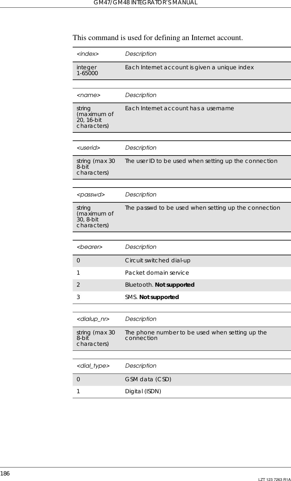
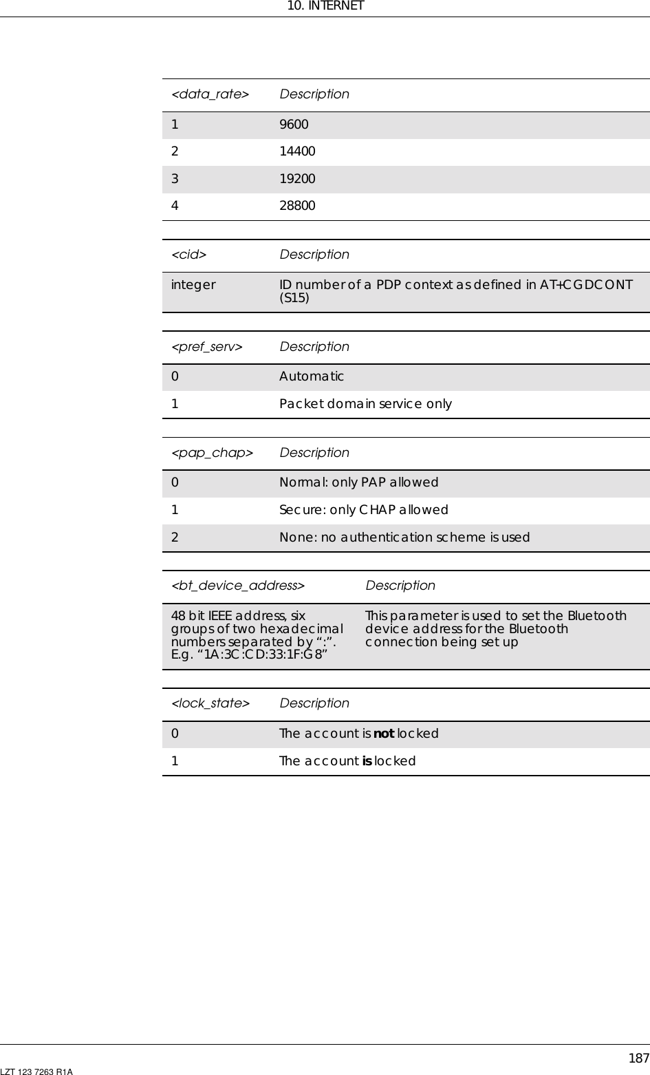
![185LZT 123 7263 R1A10. Internet10.1 AT*ENAD Ericsson Internet Account DefineDescription Command Possible ResponsesDefine anInternetaccountAT*ENAD=[<index>][,<name>,<userid>,<password>,<bearer>,(bearer_settings)]If <bearer>=0(bearer_settings):=<dialup_nr>,<dial_type>, <data_rate>If <bearer>=1(bearer_settings):=<pref_serv>,<pap_chap>If <bearer>=2(bearer_settings):=<bt_device_address>•*ENAD:<index>[,<cid>]•+CMEERROR<err>Read thecurrentsettingsAT*ENAD? *ENAD:list of <index>s with corresponding<name>, <userid>, <bearer> followed bythe list of bearer dependent parametersIf <bearer>=0(bearer_settings):=<dialup_nr>,<dial_type>,<data_rate>, <lock_state>If <bearer>=1(bearer_settings):=<pref_serv>,<pap_chap>,<cid>,<lock_state>If <bearer>=2(bearer_settings):=<bt_device_address>,<lock_state>+CME ERROR <err>Test if thecommandissupportedAT*ENAD=? *ENAD:list of supported <index>s,maxlength of <name>,max length of<userid>,max length of <password>,(0),max length of ,list of supported<dial_type>s,list of supported<data_rate>s,list of supported<lock_state>s*ENAD:list of supported <index>s,maxlength of <name>,max length of<userid>,max length of <password>, (1),listof supported <pref_serv>s,list of supported<pap_chap>s,list of supported<lock_state>s*ENAD:list of supported <index>s,maxlength of <name>,max length of<userid>,max length of <password>,(2),max length of <bt_device_address>,list of supported <lock_state>s+CME ERROR <err>](https://usermanual.wiki/Sony/6220501-BV.Exhibit-8-Integrators-Manual/User-Guide-247869-Page-185.png)

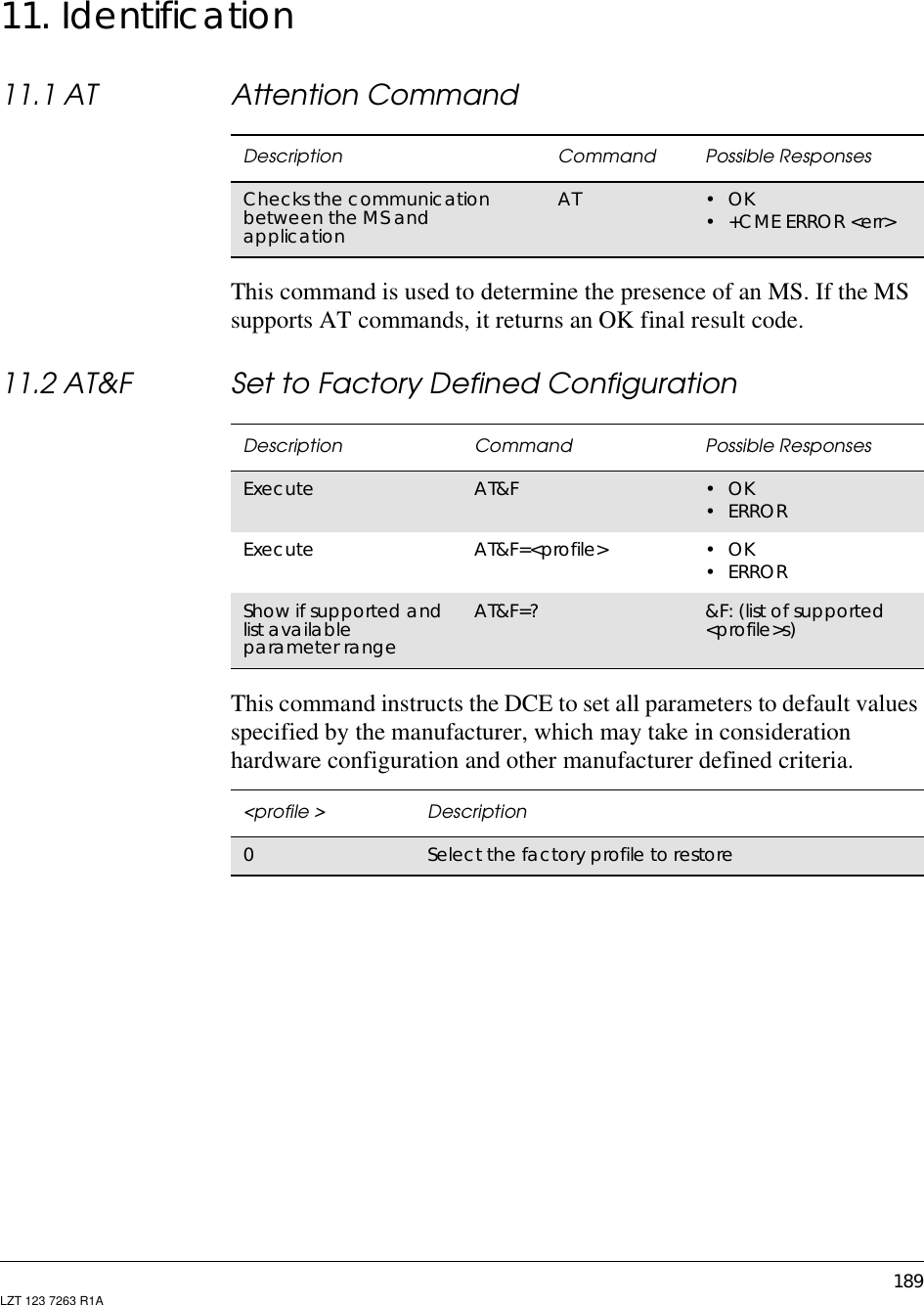
![GM47/GM48 INTEGRATOR’S MANUAL190 LZT 123 7263 R1A11.3 AT&W Store User ProfileThis command stores the current user profile in non-volatile memory.11.4 AT* List all Supported AT CommandsLists all the commands supported by the MS.11.5 AT*ESIR Read MS System Interface ReleaseCauses the MS to return the interface release.Description Command Possible ResponsesStores the current userprofile to non volatilememoryAT&W=[<pr>] orAT&W[<pr>] •OK•ERRORShow if the commandis supported AT&W=? &W: (list of supported<pr>s)<pr> Description0Stores current settings in User Profile 0Description Command Possible ResponsesList all implemented ATcommands AT* <AT Command1>[<CR> <LF><AT Command2>[…]]/<AT Command1>[<CR> <LF><AT Command2>[…]]Description Command Possible ResponsesRead MS systeminterface release AT*ESIR *ESIR:<x>.<y>Show if the commandis supported AT*ESIR=? •OK•ERROR<x> DescriptionInteger type Major version (one digit)<y> DescriptionInteger type Minor version (one digit)](https://usermanual.wiki/Sony/6220501-BV.Exhibit-8-Integrators-Manual/User-Guide-247869-Page-190.png)
![11. IDENTIFICATION191LZT 123 7263 R1A11.6 AT+CGMI Read MS Manufacturer IdentificationCauses the MS to return one or more lines of information text.]11.7 AT+CGMM Read MS Model IdentificationCauses the MS to return one or more lines of information text <model>,determined by the MS manufacturer. It is intended to permit the user ofthe ITAE/ETAE to identify the specific model of the MS to which it isconnected. Typically the text will consist of a single line containing thename of the product, but manufacturers may choose to provide moreinformation if desired.Description Command Possible ResponsesRequest manufactureridentification AT+CGMI <manufacturer>+CME ERROR: <err>Show if the commandis supported AT+CGMI=? •OK•ERROR<manufacturer> DescriptionSONY ERICSSON This company’s name in upper case lettersDescription Command Possible ResponsesRequest the modelidentification AT+CGMM <model type><modelname>+CME ERROR: <err>Show if the commandis supported AT+CGMM=? •OK•ERROR<model type> DescriptionString type A unique ASCII character/digit string, always 10characters long. Spaces are used when the number ofcharacters/digitsislessthan10<model name> DescriptionString type Model name for the transceiver unit, for example, GM47](https://usermanual.wiki/Sony/6220501-BV.Exhibit-8-Integrators-Manual/User-Guide-247869-Page-191.png)
![GM47/GM48 INTEGRATOR’S MANUAL192 LZT 123 7263 R1A11.8 AT+CGMR Read MS Revision IdentificationThis command causes the MS to return a string containing informationabout the software version.11.9 AT+CGSN Read MS Product Serial Number IdentificationThis command causes the MS to return the IMEI (International Mobilestation Equipment Identity), which identifies the individual ME.Description Command Possible ResponsesRequest MS revisionidentification string AT+CGMR <revision>+CME ERROR: <err>Show if the commandis supported AT+CGMR=? •OK•ERROR<revision> DescriptionString type An ASCII string containing date (year, month, day, hour,minute) plus KRC number.Example: 9710051610 CXC125112Description Command Possible ResponsesRequest product serialnumber AT+CGSN •+CGSN:<sn>•+CMEERROR:<err>Show if the commandis supported AT+CGSN=? •OK•ERROR<sn> DescriptionString The IMEISV, which is the IMEI (International Mobile stationEquipment Identity; refer GSM 03.03 [4]) number of the ME andthe software version number. Text shall not contain thesequence 0<CR> or OK<CR>](https://usermanual.wiki/Sony/6220501-BV.Exhibit-8-Integrators-Manual/User-Guide-247869-Page-192.png)
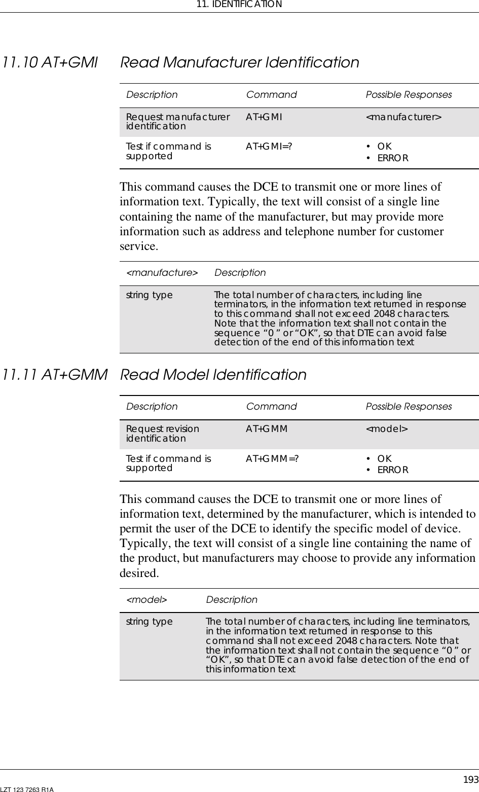
![GM47/GM48 INTEGRATOR’S MANUAL194 LZT 123 7263 R1A11.12 AT+GMR Read Revision IdentificationThis command returns a manufacturer specified software revision namein a text string.11.13 ATI Identification InformationThis command causes the DCE to transmit one or more lines of text,followed by a final result code. As an option, <value> can be used toselect from among multiple types of identifying information as shownin the table below.This command provides compatibility with Microsoft Windows 95.Description Command Possible ResponsesRequest revisionidentification AT+GMR <revision>Test if command issupported AT+GMR=? •OK•ERROR<revision> Descriptionstring type The total number of characters, including line terminators,in the information text returned in response to thiscommand shall not exceed 2048 characters. Note thatthe information text shall not contain the sequence "0" or"OK", so that DTE can avoid false detection of the end ofthis information textDescription Command Possible ResponsesExecute ATI[<value>] <information><value > Description0Same information as +GMM command (modelidentification)1Same information as +GMR command (revisionidentification)3Modem model description5Active settings7Modem configuration profile (brief listing of the modemfunctionality: fax classes, Bluetooth, IrDA, modem type,etc.)8DCEhardwaretypeversion9PnP (plug and play) information10 Same information as +GMI command (manufactureridentification). Not supported](https://usermanual.wiki/Sony/6220501-BV.Exhibit-8-Integrators-Manual/User-Guide-247869-Page-194.png)
![195LZT 123 7263 R1A12. Input/Output12.1 AT*E2IO Ericsson M2M Input/Output Read/WriteControls the operation of the general purpose I/O signals. It is possibleto perform up to 5 operations. The operations are as follows:• Read the state of the input/output signals. Digital state or digitalvalue of an ADC input or the DAC output.In case of a digital I/O, the command has the following aspect:AT*E2IO=0,“I1”*E2IO: 0,“I1”,0OKIf the requested read is focused on analogue information, the digital readis as follows:AT*E2IO=0,“AD1”*E2IO: 0,“AD1”,,62OK• Write: fixes an output with a specific value. Two possible values fordigital sources or 256 values for the analogue ones. The response isOK or ERROR if giving an output to the signal is not possible.• Configure: configuration is applicable to those signals that are bi-directional. Configuration changes the signal direction. The responseis OK, or ERROR if the signal is not bi-directional.• Configure check: checks the state of the I/Os.• Trigger: the MS can be programmed to send an unsolicited resultcode whenever a change in one of the inputs has been produced. Thetrigger has to be configured for each input.Description Command Possible ResponsesRequest operation ofthe I/O signals AT*E2IO=<op>,<io>[,<val>][,<adc_val>] •ERROR•OK•*E2IO:<op>,<io>[,<val>][,<adc_val>]OKShow if the commandis supported AT*E2IO=? •*E2IO:(listofsupported <op>s),<io>s,(list ofsupported <val>s),(list of supported<adc_val>s)•ERROR](https://usermanual.wiki/Sony/6220501-BV.Exhibit-8-Integrators-Manual/User-Guide-247869-Page-195.png)
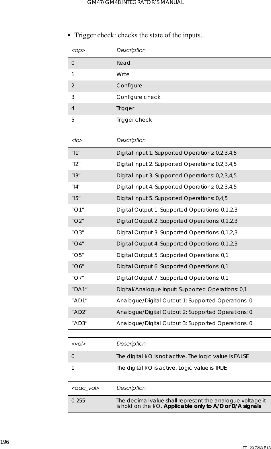
![197LZT 123 7263 R1A13. Interface13.1 AT+CPIN PIN ControlSee 3.27, AT+CPIN PIN Control13.2 AT&C Circuit 109 (DCD) ControlDetermines the behaviour of the carrier detect.13.3 AT&D Circuit 108 (DTR) ResponseControls all actions initiated by data terminal ready from DTE.Description Command Possible ResponsesSet behavior of carrierdetect AT&C[<value>] OKERROR<value> Description0DCD always on1DCD follows the connection. Default valueDescription Command Possible ResponsesControl actions fromDTE AT&D[<value>] OKERROR<value> Description0Ignore. Default value1When in on-line data mode, switch to on-line commandmode. For all other states, see <value>=22Disconnect and switch to off-line command mode](https://usermanual.wiki/Sony/6220501-BV.Exhibit-8-Integrators-Manual/User-Guide-247869-Page-197.png)
![GM47/GM48 INTEGRATOR’S MANUAL198 LZT 123 7263 R1A13.4 AT+WS46 Mode SelectionAllows an accessory to query and control the cellular protocol mode ofthe phone.13.5 ATE Command EchoThe setting of this parameter determines whether or not the DCE echoescharacters received from the DTE during command state and onlinecommand state.Description Command Possible ResponsesSets the cellularprotocol mode AT+WS46=n •OK•ERRORQueries the currentcellular protocol mode AT+WS46? •<n>OK•ERRORQueries the possiblecellular protocolmodesAT+WS46=? • (list of supported <n>s) OK•ERROR<n> parameter Description12 This value is used for GSM at 900 Mhz., DCS-1800, andPCS-1900 phonesDescription Command Possible ResponsesRequest CommandEcho ATE[<value>] •OK•ERRORShow the currentsetting ATE? <value>Show if the commandis supported ATE=? E: (list of supported<value>s)<value> Description0DCE does not echo characters during command state andonline command state1DCE echoes characters during command state and onlinecommand state. Default value](https://usermanual.wiki/Sony/6220501-BV.Exhibit-8-Integrators-Manual/User-Guide-247869-Page-198.png)
![13. INTERFACE199LZT 123 7263 R1A13.6 ATV DCE Response FormatSelect either descriptive or numeric response codes.List of result codesDescription Command Possible ResponsesSet DCE responseformat ATV[=]<value> •OK•ERRORRead the currentsetting ATV? V: <value>Show if the commandis supported ATV=? V: (list of supported<value>s)<value> Description0Display numeric result codes1Display verbose result codes. Default valueATV1 ATV0 DescriptionOK 0Acknowledges execution of acommandCONNECT 1A connection has been established;the DCE is moving from commandstate to online data stateRING 2The DCE has detected an incomingcall signal from the networkNO CARRIER 3The connection has been terminatedor the attempt to establish aconnection failedERROR 4Command not recognized, commandline maximum length exceeded,parameter value invalid, or otherproblem with processing the commandlineNO DIALTONE 6No dial tone detectedBUSY 7Engaged (busy) signal detectedNO ANSWER 8“@”(WaitforQuietAnswer)dialmodifier was used, but remote ringingfollowed by five seconds of silence wasnot detected before expiration of theconnection timerCONNECT<TEXT> Manufacturer-specific Same as CONNECT, but includesmanufacturer-specific text that mayspecify DTE speed, line speed, errorcontrol, data compression, or otherstatus](https://usermanual.wiki/Sony/6220501-BV.Exhibit-8-Integrators-Manual/User-Guide-247869-Page-199.png)
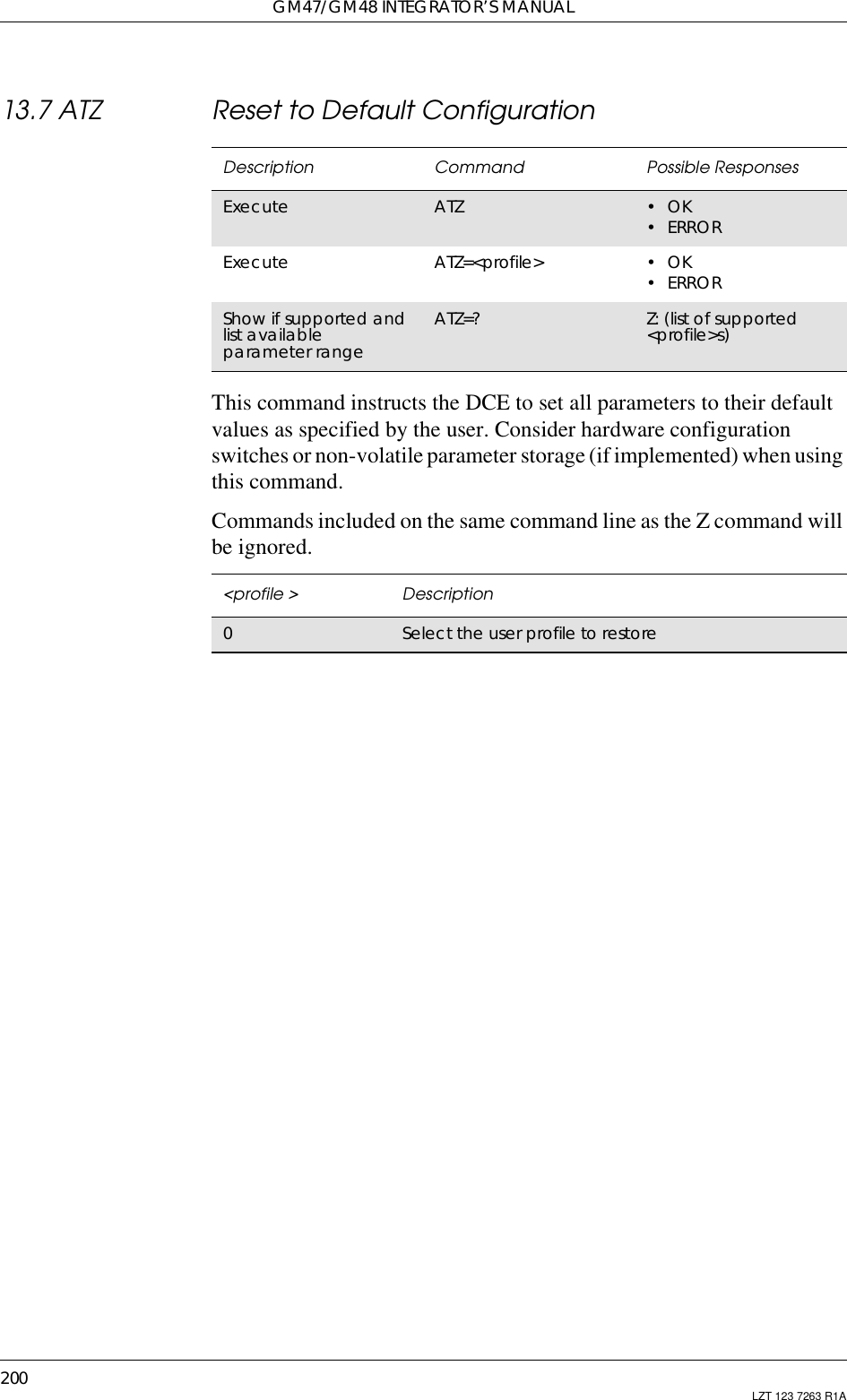
![13. INTERFACE201LZT 123 7263 R1A13.8 AT+CMUX Switch to 07.10 Multiplex ProtocolThe command is used to turn on the multiplexer. Only “notransparency” is supported. The parameter <k> is not used.Description Command Possible ResponsesSwitch to 07.10 AT+CMUX=<transparency>[,<subset>[,<port_speed>[,<N1>[,<T1>[,<N2>[,<T2>[,<T3>[,<k>]]]]]]]]•+CMEERROR:<err>•OK•ERRORReturns currentsetting formultiplexerAT+CMUX? • +CMUX:<transparency>,<subset>,<port_speed>,<N1>,<T1>,<N2>,<T2>,<T3>[,<k>]•+CMEERROR:<err>Show list ofsupportedservicesAT+CMUX=? • +CMUX: (list of supported<transparency>s),(list of supported <subset>s),(list of supported<port_speed>s),(list of supported <N1>s),(list of supported <T1>s),(list of supported <N2>s),(list of supported <T2>s),(list of supported <T3>s),(list of supported <k>)•+CMEERROR:<err><transparency> Description0No transparency1HDLC Transparency. Not supported<subset> Description0Only UIH frames used1UI frames may be used. Not supported2I frames may be used (error recovery is activated). Notsupported<port_speed> Description19600 bit/s219200 bit/s338400 bit/s457600 bit/s5115200 bit/s6230400 bit/s. Not supported](https://usermanual.wiki/Sony/6220501-BV.Exhibit-8-Integrators-Manual/User-Guide-247869-Page-201.png)
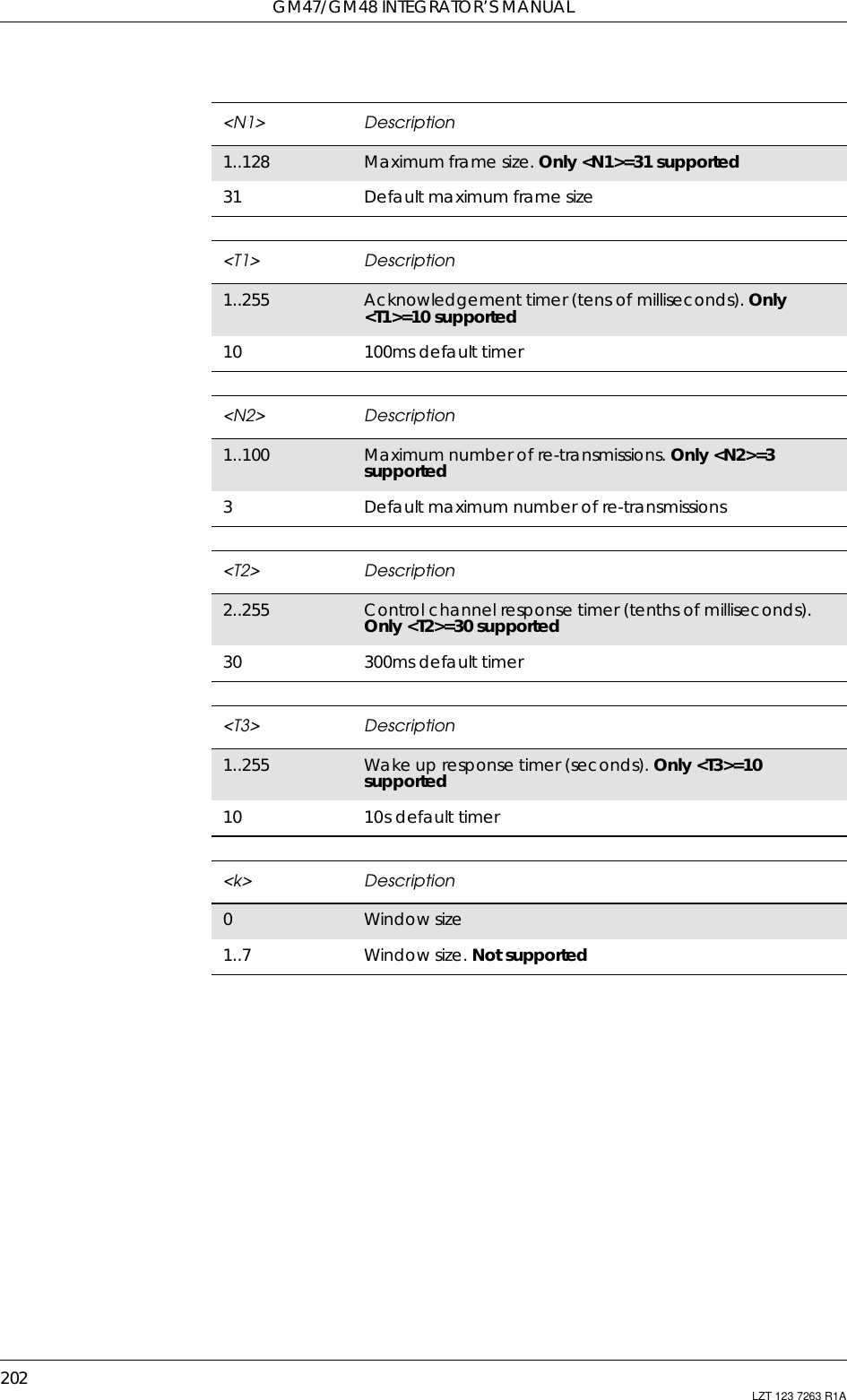
![13. INTERFACE203LZT 123 7263 R1A13.9 AT+CRES Restore SettingsRestores message service settings from non-volatile memory to activememory. A TA can contain several profiles of settings. Settingsspecified in commands Service Centre Address +CSCA, Set MessageParameters +CSMP and Select Cell Broadcast Message Types +CSCB(if implemented) are restored. Certain settings, such as SIM SMSparameters, cannot be restored.Description Command Possible ResponsesRestore settings AT+CRES[=<profile>] • +CMS ERROR: <err>•OK•ERRORGet available profiles AT+CRES=? •+CRES:(listofsupported<profile>s)• +CMS ERROR: <err>•OK•ERROR<profile> Description0..2 Profilenumberwheresettingsaretobestored.Defaultiszero](https://usermanual.wiki/Sony/6220501-BV.Exhibit-8-Integrators-Manual/User-Guide-247869-Page-203.png)
![GM47/GM48 INTEGRATOR’S MANUAL204 LZT 123 7263 R1A13.10 AT+ICF Cable Interface Character FormatThis extended-format compound parameter is used to determine thelocal serial port start-stop (asynchronous) character framing used by theDCE to accept DTE commands, and while transmitting information textand result code, if this is not automatically determined; (Notsupported) +IPR=0 forces +ICF=0 (see +IPR).Description Command Possible ResponsesDefines DTE-DCEcharacter framing AT+ICF=[format[,parity]] •OK•ERRORRead the currentsetting AT+ICF? •+ICF:<format>,<parity>•OK•ERRORShow if thecommand issupportedAT+ICF=? •+ICF:(listofsupported<format>s), (list ofsupported <parity>s)•OK•ERROR<format> Description0auto detect. Not supported18Data2Stop.Not supported28Data1Parity1Stop.Not supported38Data1Stop.Default value47Data2Stop.Not supported57Data1Parity1Stop.Not supported67Data1Stop.Not supported<parity> Description0Odd. Not supported1Even. Not supported2Mark. Not supported3Space. Default value](https://usermanual.wiki/Sony/6220501-BV.Exhibit-8-Integrators-Manual/User-Guide-247869-Page-204.png)
![13. INTERFACE205LZT 123 7263 R1A13.11 AT+IFC DTE-DCE Local Flow ControlDefines the flow control between the modem and the computer when inon-line data mode.No flow control is enabled in any of the command modes.13.12 AT+ILRR Cable Interface Local Rate ReportingSpecifies whether or not the extended-format “+ILRR:<rate>”information text is transmitted from the DCE to the DTE. The <rate>reported shall represent the current (negotiated or renegotiated) DTE-DCE rate. If enabled, the intermediate result code is transmitted afterany modulation, error control or data compression reports areDescription Command Possible ResponsesDefines DTE-DCE localflow control AT+IFC=[<by_te>,[<by_ta>]] •OK•ERRORRead the currentsetting AT+IFC? +IFC: <by_te>,<by_ta>Show if the commandis supported AT+IFC=? +IFC: (list of supported<by_te>s,<by_ta>s)<by_te> Description0No flow control on DTE1Xon/Xoff flow control on DCE. Control characters areremovedbytheDCEinterface2RTS flow control on DCE. Default value3Xon/Xoff flow control on DCE. Control characters arepassed to the remote DCE/DTE<by_ta> Description0No flow control on DCE1Xon/Xoff flow control on DTE2CTS flow control on DCE. Default valueDescription Command Possible ResponsesDefines DTE-DCEcharacter framing AT+ILRR=<value> •OK•ERRORRead the currentsetting AT+ILRR? +ILRR:<value>Show if the commandis supported AT+ILRR=? +ILRR:(list of supported<values>s)](https://usermanual.wiki/Sony/6220501-BV.Exhibit-8-Integrators-Manual/User-Guide-247869-Page-205.png)
![GM47/GM48 INTEGRATOR’S MANUAL206 LZT 123 7263 R1Atransmitted, and before any final result code (e.g. CONNECT) istransmitted. The <rate> is applied after the final result code istransmitted.13.13 AT+IPR Cable Interface Port CommandSpecifies the data rate at which the DCE will accept commands, inaddition to 1200 bit/s or 9600 bit/s (as required in v25ter [1], subclause4.3). It may be used to select operation at rates used by the DTE, whichthe DCE is not capable of automatically detecting.(Not supported) Specifying a value of 0 disables the function andallows operation only at rates automatically detectable by the DCE.The specified rate takes effect following the issuance of any resultcode(s) associated with the current command line.<value> Description0Disables reporting of local port rate (+ILRR: is nottransmitted). Default value1Enables reporting of local port rate (+ILRR: is transmitted)Description Command Possible ResponsesDefines fixed DTE rate AT+IPR=[rate] •OK•ERRORRead the currentsetting AT+IPR? •+IPR:<rate>•OK•ERRORShow if the commandis supported AT+IPR=? • +IPR: (), (list of fixed-only <rate>s)]•OK•ERROR<rate> DescriptionDiscreteinteger value The <rate>valuespecifiedshallbetherateinbitspersecond at which the DTE-DCE interface should operate,e.g. “19200” or “115200”. The rates supported by aparticular DCE are manufacturer specific.The following rates, are supported (with two exceptions);120024004800960014400 (Not supported)1920028800 (Not supported)384005760076800115200230400460800](https://usermanual.wiki/Sony/6220501-BV.Exhibit-8-Integrators-Manual/User-Guide-247869-Page-206.png)
![13. INTERFACE207LZT 123 7263 R1A13.14 AT*E2ESC M2M Escape Sequence Guard TimeDefines a guard time for the escape sequence in GPRS to return to on-line command mode i.e. if +++AT<CR> is received either as part of thedata stream or a terminating string from the application and no furtherdata is received for the duration of the guard time the module will gointo on line command mode. This guards against the moduleaccidentally going into on line command mode.Description Syntax Possible responsesSet GPRS onlinecommand guard time AT*E2ESC=[<gt>] •OK•ERRORRead the currentsetting AT*E2ESC? *E2ESC: <gt>Show if the commandis supported AT*E2ESC=? •OK•ERROR<gt> Description0No guard time. Default value1-10 Guard time in seconds](https://usermanual.wiki/Sony/6220501-BV.Exhibit-8-Integrators-Manual/User-Guide-247869-Page-207.png)

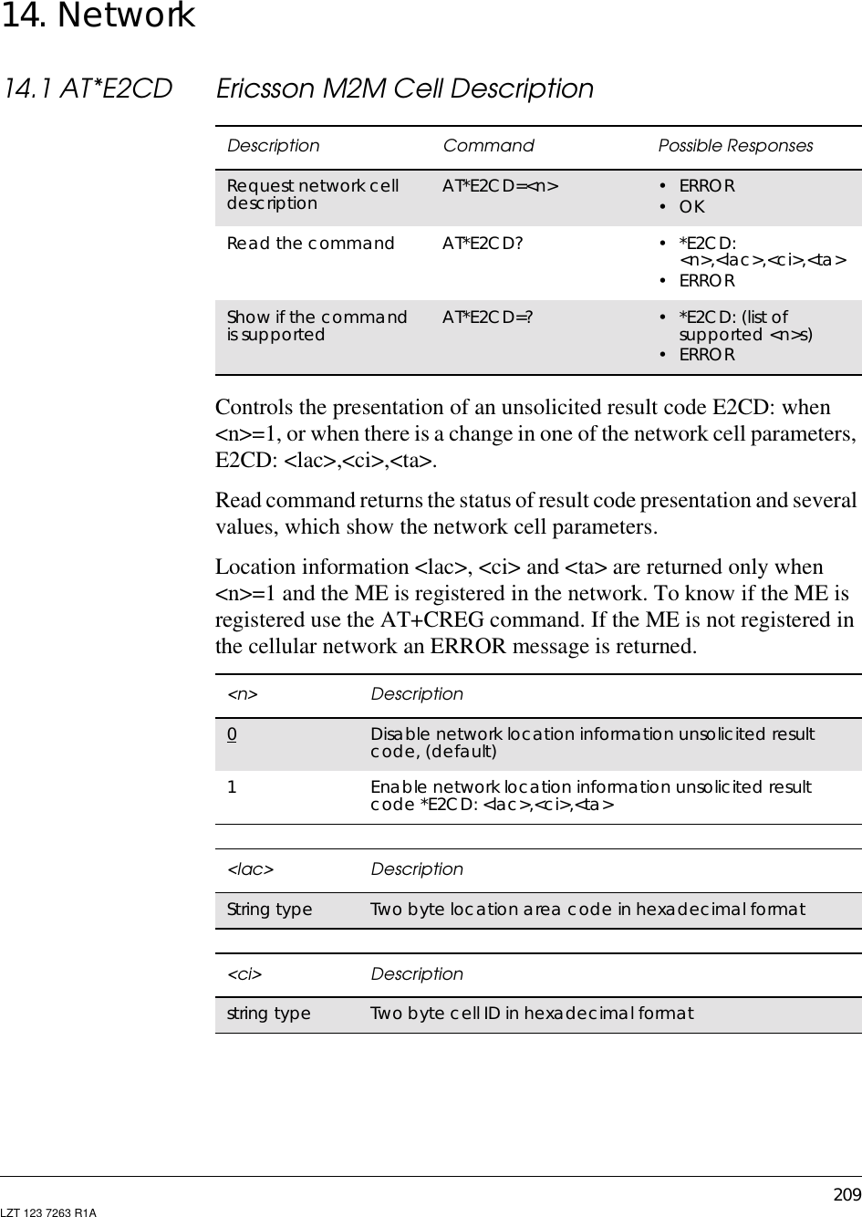
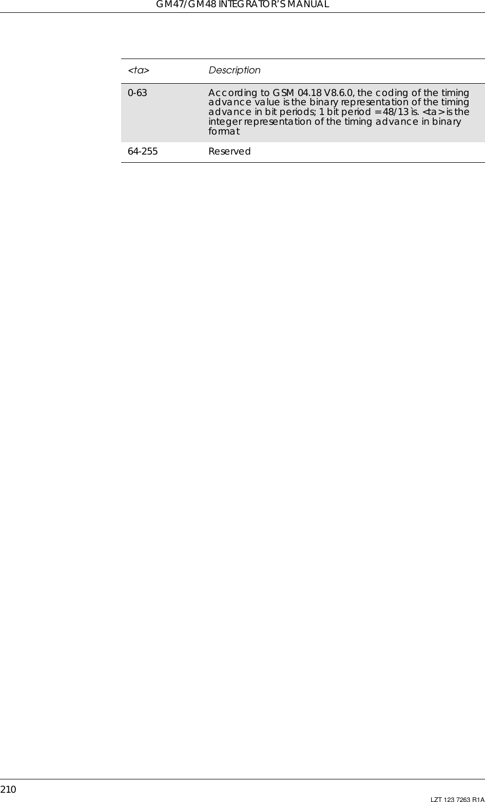
![14. NETWORK211LZT 123 7263 R1A14.2 AT*E2EMM Ericsson M2M Engineering Monitoring ModeDescription Command Possible ResponsesSet theresponsepresentationmodeAT*E2EMM=<n>[,<m>] • ERROR•OKDisplay modeneighbour cellsare taken fromthe toplist*E2EMM:Serving CellMCC,MNC,LAC,CellID,BSIC,Ch[,RxL,C1,C2][,RxLFull,RxLSub,RxQFull,RxQSub,TA,TN],<mcc>,<mnc>,<lac>,<ci>,<bsic>,<ch>[,<rxl>,<c1>,<c2>][,<rxlFull>,<rxlSub>,<rxqfull>,<rxqsub>,<ta>,<tn>],NeighBours CellsMCC,MNC,LAC,CellID,BSIC,Ch,RxL[,C1,C2],<mcc>,<mnc>,<lac>,<ci>,<bsic>,<ch>,<rxl>[,<c1>,<c2>]<mcc>,<mnc>,<lac>,<ci>,<bsic>,<ch>,<rxl>[,<c1>,<c2>]…<mcc>,<mnc>,<lac>,<ci>,<bsic>,<ch>,<rxl>[,<c1>,<c2>]OKCompact mode.The first cell is theserving cell, therest areneighbour cellstaken from thetoplist*E2EMM: <mcc>,<mnc>,<ci>,<bsic>,<ch>[,<rxl>][,<rxlSub>,<rxqsub>,<ta>],<mcc>,<mnc>,<ci>,<bsic>,<ch>,<rxl>,<mcc>,<mnc>,<ci>,<bsic>,<ch>,<rxl>,…<mcc>,<mnc>,<ci>,<bsic>,<ch>,<rxl>OKVerbose mode.The first cell is theserving cell andthe rest areneighbour cellsas provided bythe network inthe system info.messages (2 and5) and via theAT*E2NBTScommand*E2EMM: <mcc>,<mnc>,<lac>,<ci>,<bsic>,<ch>[,<rxl>,<c1>,<c2>][,<rxlFull>,<rxlSub>,<rxqfull>,<rxqsub>,<ta>,<tn>],<mcc>,<mnc>,<lac>,<ci>,<bsic>,<ch>,<rxl>[,<c1>,<c2>]<mcc>,<mnc>,<lac>,<ci>,<bsic>,<ch>,<rxl>[,<c1>,<c2>]…<mcc>,<mnc>,<lac>,<ci>,<bsic>,<ch>,<rxl>[,<c1>,<c2>]OKReduced displaymode - info. asdisplay mode butwithout textheadings or<CR><LF>separators,neighbour cellsfrom top list*E2EMM: <mcc>,<mnc>,<lac>,<ci>,<bsic>,<ch>[,<rxl>,<c1>,<c2>][,<rxlFull>,<rxlSub>,<rxqfull>,<rxqsub>,<ta>,<tn>],<mcc>,<mnc>,<lac>,<ci>,<bsic>,<ch>,<rxl>[,<c1>,<c2>]<mcc>,<mnc>,<lac>,<ci>,<bsic>,<ch>,<rxl>[,<c1>,<c2>]…<mcc>,<mnc>,<lac>,<ci>,<bsic>,<ch>,<rxl>[,<c1>,<c2>]OKRead thecommand AT*E2EMM? • *E2EMM: <n>• ERRORShow if thecommand issupportedAT*E2EMM=?• *E2EMM: (list of supported <n>s),(listof supported <m>s)• ERROR](https://usermanual.wiki/Sony/6220501-BV.Exhibit-8-Integrators-Manual/User-Guide-247869-Page-211.png)
![GM47/GM48 INTEGRATOR’S MANUAL212 LZT 123 7263 R1AThere are four presentation format modes (Display, Compact, Verbose,and Reduced Display) and two response types (one shot response orcontinuous unsolicited responses).The purpose of the presentation format mode Display is to display thedata in a readable form, including headers and line breaks(<CR><LF>). This format is, however, not well suited for machinedecoding. The formats Verbose, Compact and Reduced Display do nothave headers or line breaks. Verbose mode displays more parametersthan the compact mode.The response types give the user the choice of one a shot information oran unsolicited response with <m> seconds between each response.ExamplesAT*E2EMM=1*E2EMM:<CR><LF>Serving Cell<CR><LF>MCC,MNC,LAC,CellID,BSIC,Ch[,RxL,C1,C2][,RxLFull,RxLSub,RxQFull,RxQSub,TA,TN]<CR><LF><mcc>,<mnc>,<lac>,<ci>,<bsic>,<ch>[,<rxl>,<c1>,<c2>][,<rxlFull>,<rxlSub>,<rxqfull>,<rxqsub>,<ta>,<tn>]<CR><LF>NeighBours Cells<CR><LF>MCC,MNC,LAC,CellID,BSIC,Ch,RxL[,C1,C2]<CR><LF><mcc>,<mnc>,<lac>,<ci>,<bsic>,<ch>,<rxl>[,<c1>,<c2>]<CR><LF><mcc>,<mnc>,<lac>,<ci>,<bsic>,<ch>,<rxl>[,<c1>,<c2>]<CR><LF>…<mcc>,<mnc>,<lac>,<ci>,<bsic>,<ch>,<rxl>[,<c1>,<c2>]<CR><LF>OKAT*E2EMM=3*E2EMM: <servcell mcc>,<servcell mnc>,<servcell ci>,<servcellbsic>,<servcell ch>[,<servcell rxl>][,<servcell rxlSub>,<servcellrxqsub>,<servcell ta>],<neighborcell1 mcc>,<neighborcell1mnc>,<neighborcell1 ci>,<neighborcell1 bsic>,<neighborcell1ch>,<neighborcell1 rxl>,<neighborcell2 mcc>,<neighborcell2mnc>,<neighborcell2 ci>,<neighborcell2 bsic>,<neighborcell2ch>,<neighborcell2 rxl>,…<neighborcelln mcc>,<neighborcellnmnc>,<neighborcellnci>,<neighborcelln bsic>,<neighborcelln ch>,<neighborcellnrxl><CR><LF>OKAT*E2EMM=5*E2EMM: <servcell mcc>,<servcell mnc>,<servcell lac>,<servcellci>,<servcell bsic>,<servcell ch>[,<servcell rxl>,<servcellC1>,<servcell C2>][,<servcell rxlFull>,<servcell rxlSub>,<servcellrxqfull>,<servcell rxqsub>,<servcell tn>,<servcell ta>],](https://usermanual.wiki/Sony/6220501-BV.Exhibit-8-Integrators-Manual/User-Guide-247869-Page-212.png)
![14. NETWORK213LZT 123 7263 R1A<neighborcell1 mcc>,<neighborcell1 mnc>,<neighborcell1lac>,<neighborcell1 ci>,<neighborcell1 bsic>,<neighborcell1ch>,<neighborcell1 rxl>[,<neighborcell1 C1>,<neighborcell1C2>],<neighborcell2 mcc>,<neighborcell2 mnc>,<neighborcell2lac>,<neighborcell2 ci>,<neighborcell2 bsic>,<neighborcell2ch>,<neighborcell2 rxl>[,<neighborcell2 C1>,<neighborcell2 C2>],…<neighborcelln mcc>,<neighborcellnmnc>,<neighborcellnlac>,<neighborcelln ci>,<neighborcelln bsic>,<neighborcellnch>,<neighborcelln rxl> [,<neighborcelln C1>,<neighborcellnC2>]<CR><LF>OKAT*E2EMM=7*E2EMM:<servcell mcc>,<servcell mnc>,<servcell lac>,<servcellci>,<servcell bsic>,<servcell ch>[,<servcell rxl>,<servcellc1>,<servcell c2>][,<servcell rxlFull>,<servcell rxlSub>,<servcellrxqfull>,<servcell rxqsub>,<servcell ta>,<servcell tn>],<neighborcell1mcc>,< neighborcell1 mnc>,<neighborcell1 lac>,<neighborcell1ci>,<neighborcell1 bsic>,<neighborcell1 ch>,<neighborcell1 rxl>[,<neighborcell1 c1>,<neighborcell1 c2>],<neighborcell2mcc>,<neighborcell2 mnc>,<neighborcell2 lac>,<neighborcell2ci>,<neighborcell2 bsic>,<neighborcell2 ch>,<neighborcell2rxl>[,<neighborcell2 c1>,<neighborcell2c2>]…<neighborcelln mcc>,<neighborcelln mnc>,<neighborcellnlac>,<neighborcelln ci>,<neighborcelln bsic>,<neighborcellnch>,<neighborcelln rxl>[,<neighborcelln c1>,<neighborcelln c2>]OKThe mode setting <n> in the set command has the combination listed inthe table below.When <n>=5, the shot information is the same as in <n> = 1, butneighbouring cells, which have to be up to 16. This is the informationthat comes from the Serving Cell through the BCCH, reporting the BTSthat are on the Serving Cell's surroundings.<n> Description0Disable network monitoring unsolicited result code.Default1One shot presentation of the network locationinformation. Display mode with headers and <CR><LF>line separators2Enable network location information unsolicited resultcode in Display mode (like n=1). There will be continuousunsolicited information responses <m> seconds apart3One shot presentation of the compact network locationinformation](https://usermanual.wiki/Sony/6220501-BV.Exhibit-8-Integrators-Manual/User-Guide-247869-Page-213.png)
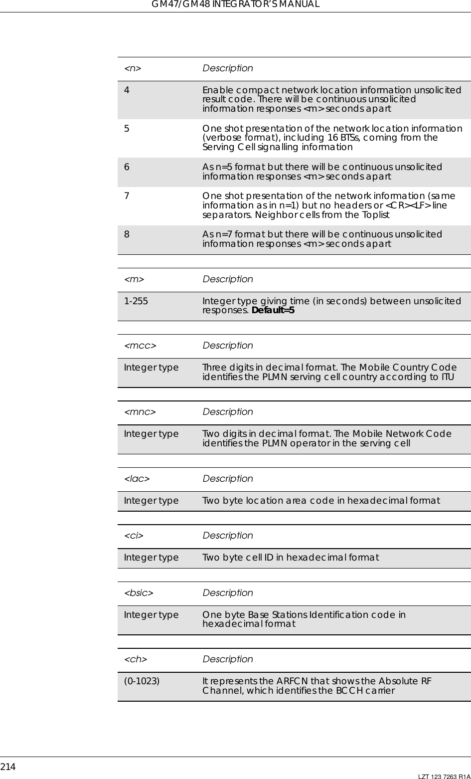
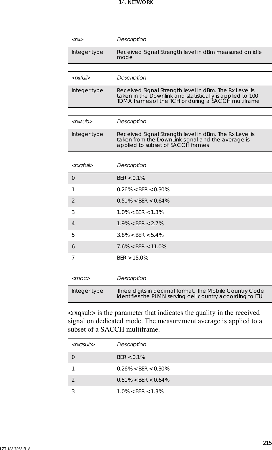
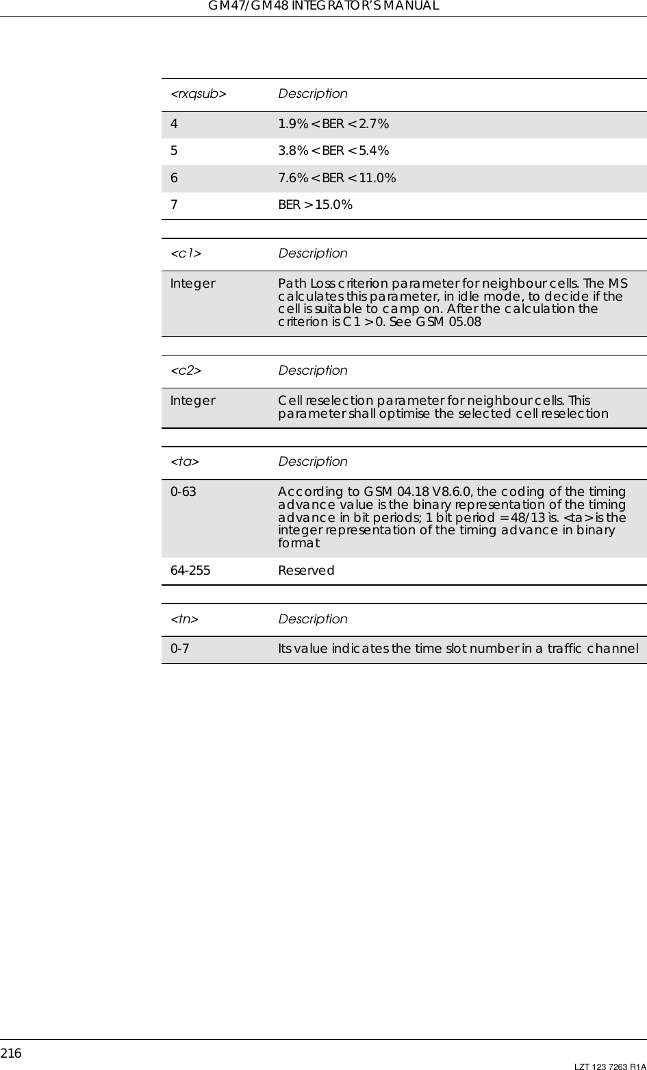
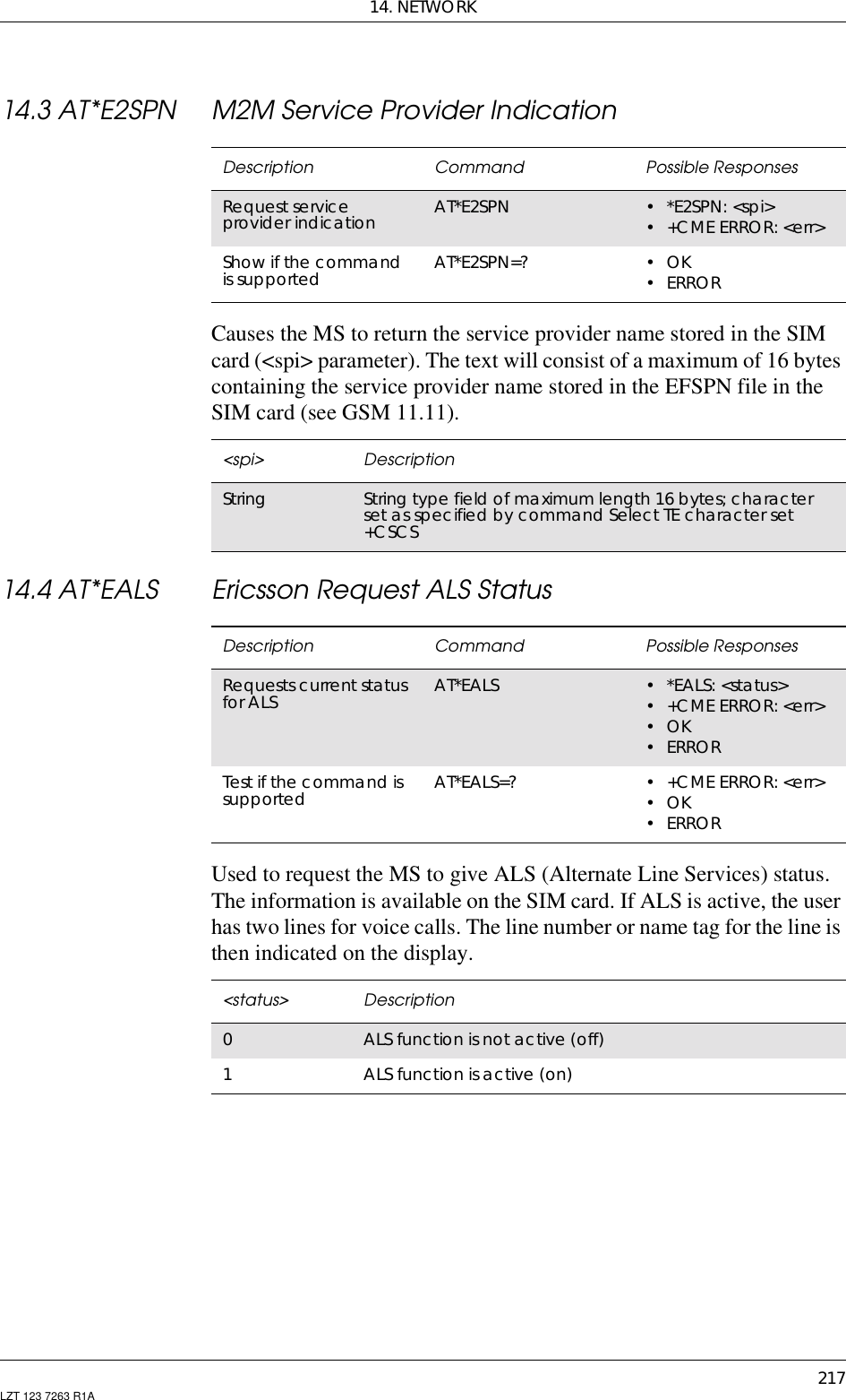
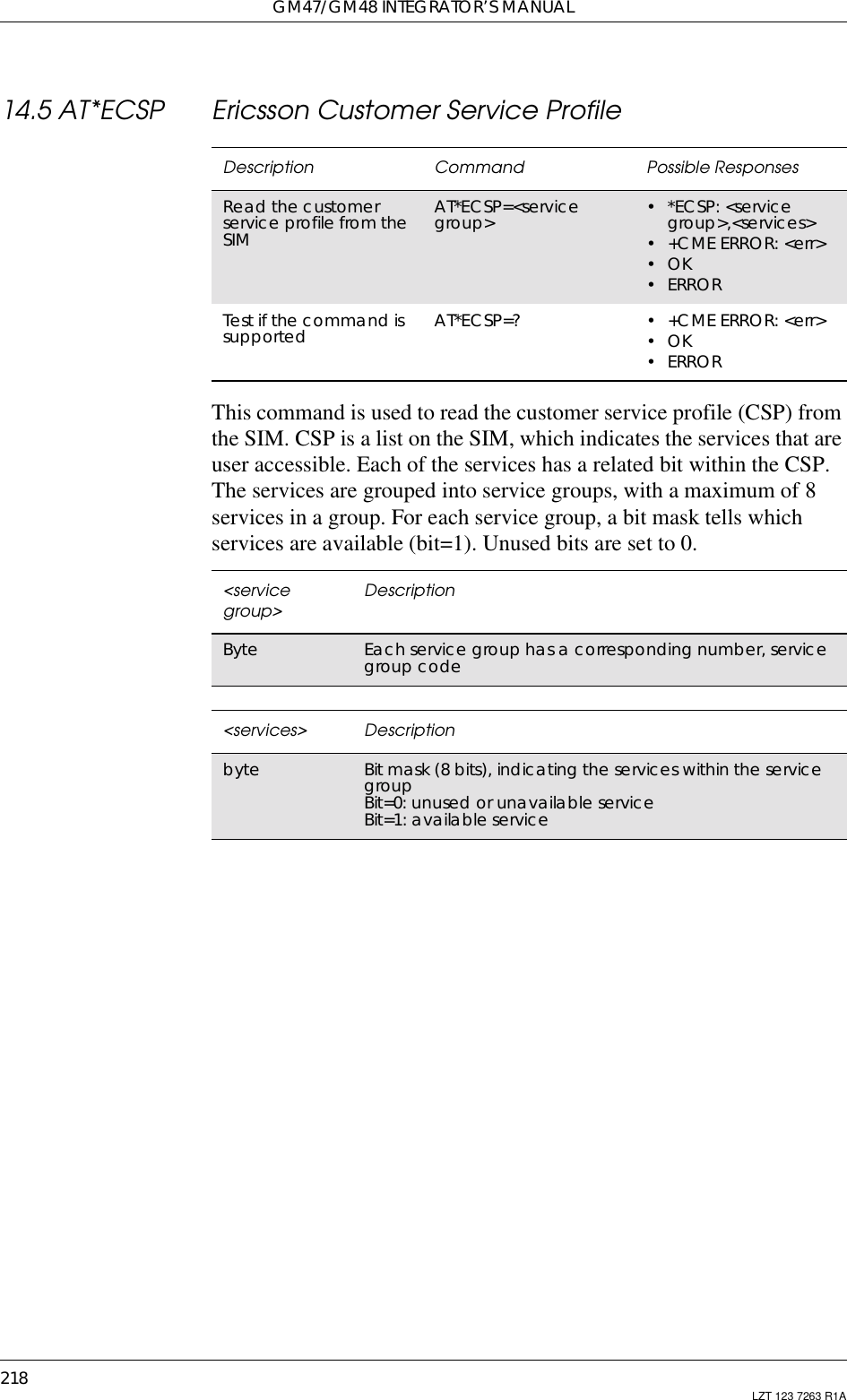
![14. NETWORK219LZT 123 7263 R1A14.6 AT*EPNR Ericsson Read SIM Preferred NetworkThis command is used to read the SIM preferred list of networks(EFPLMNsel).Description Command Possible ResponsesRead entries in SIMpreferred list AT*EPNR=<format>[,<index1>[,<index2]]•*EPNR:<index1>,<oper1>[...]*EPNR: <index2>,<oper2>•+CMEERROR:<err>•OK•ERRORTest if the command issupported and list thepossible settingsAT*EPNR=? •*EPNR:(listofsupported <index>s),(list of supported<format>s)•+CMEERROR:<err>•OK•ERROR<index1> Descriptioninteger Start index (>0)<index2> Descriptioninteger Stop index (>0)<format> Description2Numeric <oper><oper> Descriptionstring String indicates the code for the operator.E.g. GSM - Sweden - Europolitan: “24008” (3 + 2).PCS: 3 digits for country and 3 digits for network](https://usermanual.wiki/Sony/6220501-BV.Exhibit-8-Integrators-Manual/User-Guide-247869-Page-219.png)
![GM47/GM48 INTEGRATOR’S MANUAL220 LZT 123 7263 R1A14.7 AT*EPNW Ericsson Write SIM Preferred NetworkThis command is used to edit the SIM preferred list of networks(EFPLMNsel). The entry field <oper> contains mobile country code(MCC) and mobile network code (MNC).Description Command Possible ResponsesWrite/delete entries inSIM preferred list AT*EPNW=[<index>][,<format>,<oper>] •+CMEERROR:<err>•OK•ERRORTest if the command issupported and list thepossible settingsAT*EPNW=? •*EPNW:(listofsupported<index>s), (list ofsupported<format>)s•+CMEERROR:<err>•OK•ERROR<index> DescriptionInteger Index to entry in SIM preferred list.The SIM preferred list contains at least 8 positionsaccording to GSM 11.11<format> Description0Long format alphanumeric <oper>. Not supported1Shortformatalphanumeric<oper>.Not supported2Numeric <oper><oper> DescriptionString String indicates the code for the operator.E.g. GSM – Sweden - Europolitan: “24008” (3 + 2).PCS: 3 digits for country and 3 digits for network](https://usermanual.wiki/Sony/6220501-BV.Exhibit-8-Integrators-Manual/User-Guide-247869-Page-220.png)
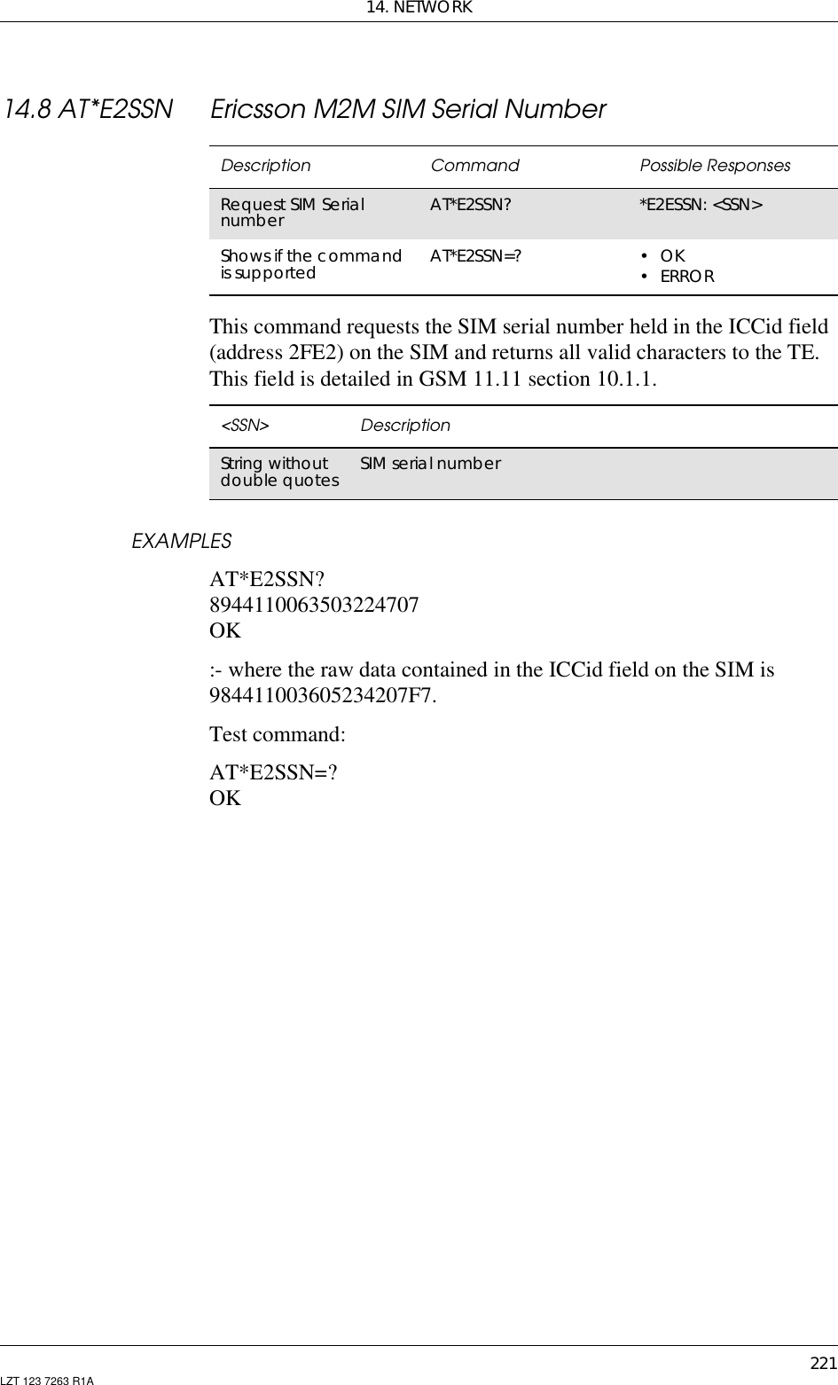
![GM47/GM48 INTEGRATOR’S MANUAL222 LZT 123 7263 R1A14.9 AT*ESLN Ericsson Set Line NameSets the name tag for a selected line.Description Command Possible ResponsesSets the line name tagin the MS AT*ESLN=<line>[,<name>] • +CME ERROR: <err>•OK•ERRORRead the currentsetting AT*ESLN? •*ESLN:<line1>,<name1><CR><LF>*ESLN: <line2>,<name2>• +CME ERROR: <err>•OK•ERRORTest if the command issupported and list thepossible settingsAT*ESLN=? • *ESLN: (list of supported<line>s),<lname>• +CME ERROR: <err>•OK•ERROR<line> Description0Default. This means that the two lines will use the defaultnametags,i.e."L1"and"L2"1Line 12Line 2<name> DescriptionString Characters for name tagThis parameter is optional when <line> is set to 0<lname> DescriptionInteger Max. number of characters to use in <name> string (20)](https://usermanual.wiki/Sony/6220501-BV.Exhibit-8-Integrators-Manual/User-Guide-247869-Page-222.png)
![14. NETWORK223LZT 123 7263 R1A14.10 AT+CIMI Subscriber IdentificationCauses the TA to return <IMSI>, identifying the individual SIMattached to the ME.14.11 AT+CLCK Facility LockThe command is used to lock, unlock or interrogate an ME or a networkfacility <fac>. A password is normally needed to carry out such actions.Call barring facilities are based on GSM supplementary services (referto GSM 02.88 [6]). The interaction of these, with other commandsbased on other GSM supplementary services, is described in the GSMstandard.Description Syntax Possible ResponsesRead IMSI AT+CIMI •<IMSI>• +CME ERROR <err>•OK•ERRORShow if the commandis supported AT+CIMI=? •OK•ERROR<IMSI> Descriptionstring withoutdouble quotes International Mobile Subscriber IdentityDescription Command Possible ResponsesRequest facility lock AT+CLCK=<fac>,<mode>[,<passwd>[,<class>]]• when <mode>=2 andcommand successful:+CLCK:<status>[,<class1>[<CR><LF>+CLCK:<status>,<class2>[...]]• +CME ERROR <err>•OK• ERRORShow if thecommand issupportedAT+CLCK=? •+CLCK:(listofsupported <fac>s)• +CME ERROR <err>•OK<fac > Description“CS” CNTRL (lock CoNTRoL surface (e.g. phone keyboard))“PS” PH-SIM (lock PHone to SIM card) (ME asks password whenother than current SIM card inserted)“SC” SIM (lock SIM card) (SIM asks password in ME power-upand when this lock command issued)“P2” SIM PIN2](https://usermanual.wiki/Sony/6220501-BV.Exhibit-8-Integrators-Manual/User-Guide-247869-Page-223.png)
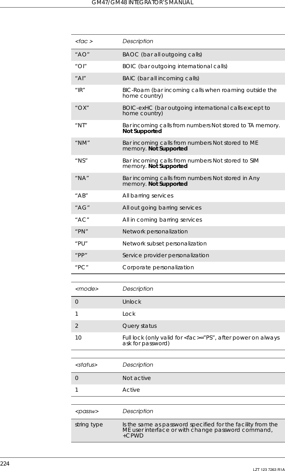
![14. NETWORK225LZT 123 7263 R1A14.12 AT+CNUM Subscriber NumberThis command returns the MSISDNs related to the subscriber (thisinformation can be stored in the SIM or in the ME). If subscriber hasdifferent MSISDN for different services, each MSISDN is returned in aseparate line.<classx> Description1Voice L12Data4Fax8Short message service16 Data circuit sync32 Data circuit async64 Dedicated packet access128 Voice L21..30 When “no reply” is enabled or queried, this gives the timein seconds to wait before the call is forwarded. Defaultvalue is 20Description Command Possible ResponsesRequest subscribernumber AT+CNUM •+CNUM:[<alpha1>],<number1>,<type1>[,<speed>,<service>[,<itc>]][<CR><LF>+CNUM:[<alpha2>],<number2>,<type2>[,<speed>,<service> [,<itc>]][…]]• +CME ERROR: <err>•OK• ERRORShow if thecommand issupportedAT+CNUM=? • +CME ERROR: <err>•OK• ERROR<alphax> DescriptionAlphanumericstring Associated with <numberx>; used characterset should bethe one selected with the Select TE character setcommand, +CSCS<numberx> DescriptionString type Phone number of format specified by <typex><typex> DescriptionInteger format Type of address, (refer to GSM 04.08 [3] subclause 10.5.4.7)](https://usermanual.wiki/Sony/6220501-BV.Exhibit-8-Integrators-Manual/User-Guide-247869-Page-225.png)
![GM47/GM48 INTEGRATOR’S MANUAL226 LZT 123 7263 R1A<speed> Descriptiondata rate As defined in subclause 6.7 GSM 07.07 [1]<service> Description0Asynchronous modem1Synchronous modem. Not supported2PAD access (asynchronous). Not supported3Packet access (synchronous). Not supported4Voice5Fax6..127 All other values below 128 are reserved by GSM 07.07 [1].Not supported<itc> Description03.1kHz1UDI](https://usermanual.wiki/Sony/6220501-BV.Exhibit-8-Integrators-Manual/User-Guide-247869-Page-226.png)
![14. NETWORK227LZT 123 7263 R1A14.13 AT+COPS Operator SelectionForces an attempt to select and register the GSM network operator.Description Command Possible ResponsesRequest operatorselection AT+COPS=[<mode>[,<format>[,<oper>]]]• +CME ERROR <err>•OK• ERRORShows the currentsetting AT+COPS? •+COPS:<mode>[,<format>,<oper>]• +CME ERROR <err>•OK• ERRORShow if the commandis supported AT+COPS=? • +COPS:list of supported(<stat>,longalphanumeric <oper>,short alphanumeric<oper>,numeric<oper>)s• +CME ERROR <err>•OK• ERROR<mode> Description0Automatic (<oper> field is ignored)1Manual (<oper> field shall be present)3Set only <format> (for read command +COPS?), do notattempt registration/de-registration (<oper> field isignored); this value is not applicable in read commandresponse4Manual/automatic (<oper> field shall be present); ifmanual selection fails, automatic mode (<mode>=0) isentered<format> Description0Automatic (<oper> field is ignored)1Shortformatalphanumeric<oper>2Numeric <oper><oper> Descriptionstring type Format determined by the <format> setting](https://usermanual.wiki/Sony/6220501-BV.Exhibit-8-Integrators-Manual/User-Guide-247869-Page-227.png)
![GM47/GM48 INTEGRATOR’S MANUAL228 LZT 123 7263 R1A14.14 AT+CREG Network RegistrationControls the presentation of the unsolicited result code +CREG.<stat> Description0Unknown1Available2Current3ForbiddenDescription Command Possible ResponsesRequest networkregistration AT+CREG=[<n>] • +CME ERROR <err>•OK•ERRORRead the command AT+CREG? •+CREG:<n>,<stat>• +CME ERROR <err>•OK•ERRORShow if the commandis supported AT+CREG=? •+CREG:(listofsupported <n>s)• +CME ERROR <err>•OK•ERROR<n> Description0Disable network registration unsolicited result code,(default)1Enable network registration unsolicited result code<stat> Description0Not registered, ME is not currently searching for a newoperator to register with1Registered, home network2Notregistered,butMEiscurrentlysearchingforanewoperator to register with3Registration denied](https://usermanual.wiki/Sony/6220501-BV.Exhibit-8-Integrators-Manual/User-Guide-247869-Page-228.png)
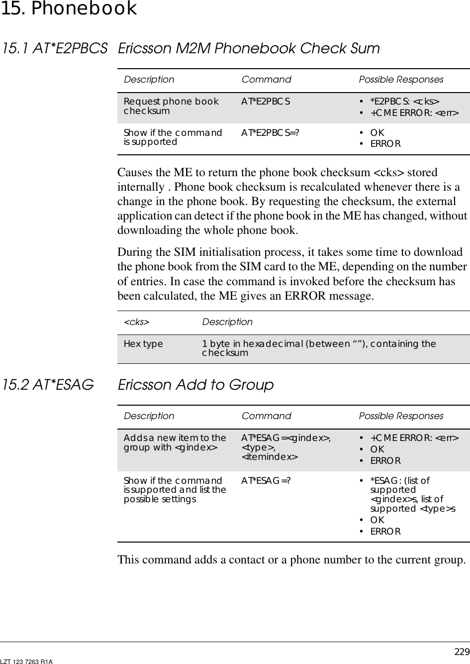
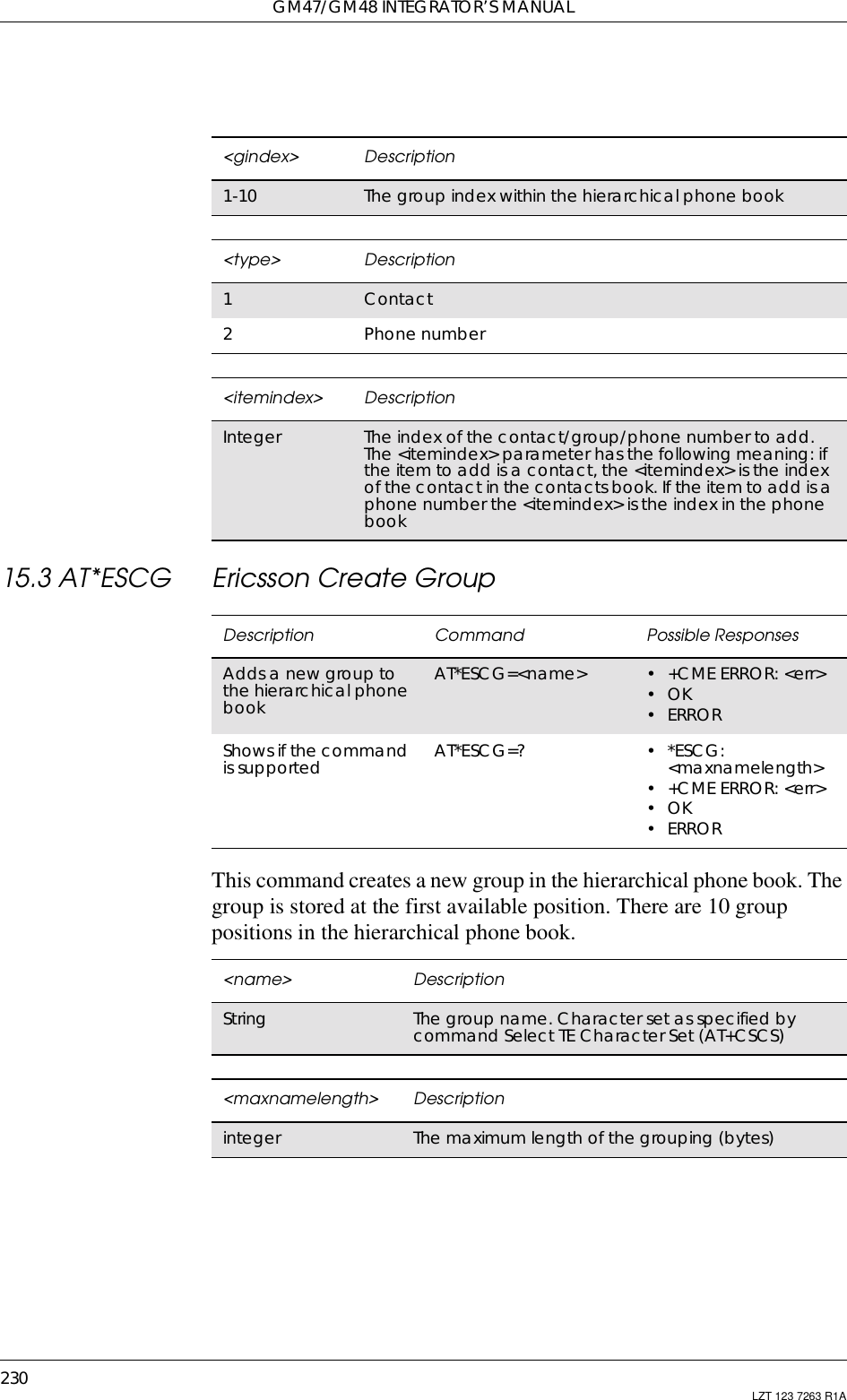
![15. PHONEBOOK231LZT 123 7263 R1A15.4 AT*ESCN Ericsson Set Credit Card NumberCommand is used to:• set up a credit card number in the ME.• disable credit card calls.• enable one of the credit card call services.• query the settings for one of the services.• query the active credit call access server.Description Command Possible ResponsesSet up a credit cardnumber AT*ESCN=<mode>[,<passwd>][,<indexn>][,<asn>,<type>,<name>,<vercode>[,<sendorder>]]•+CMEERROR:<err>whenmode=3:*ESCN:<indexn>,<asn>,<type>,<name>,<vercode>,<send order>Whenmode=4:*ESCN:<selindexn>•OK•ERRORTest if the command issupported AT*ESCN=? •*ESCN:(listofsupported<index>s),(list ofsupported<mode>s),(list ofsupported <sendorder>s)•+CMEERROR:<err>•OK•ERROR<mode> Description0Settings for a credit card call (<passwd>, <indexn>,<asn>,<type>,<name>,<vercode> [,<send order>]). Thefour (4) parameters (<passwd>, <indexn>, <asn>,<vercode>) are mandatory when <mode> = 0. If all thoseare not submitted ERROR will be returned1Disable credit card calling (<passwd>). If any otherparameters are submitted, they are ignored2Enable one of the credit card call services (<passwd>,<indexn>). If any other parameters are submitted, theyare ignored3Query (<passwd>, <indexn>). If any other parameters aresubmitted, they are ignored4Query for the selected credit call access server. If anyparameters are submitted, they are ignored<passwd> DescriptionString character string, phone lock code “PS”, PH-SIM](https://usermanual.wiki/Sony/6220501-BV.Exhibit-8-Integrators-Manual/User-Guide-247869-Page-231.png)
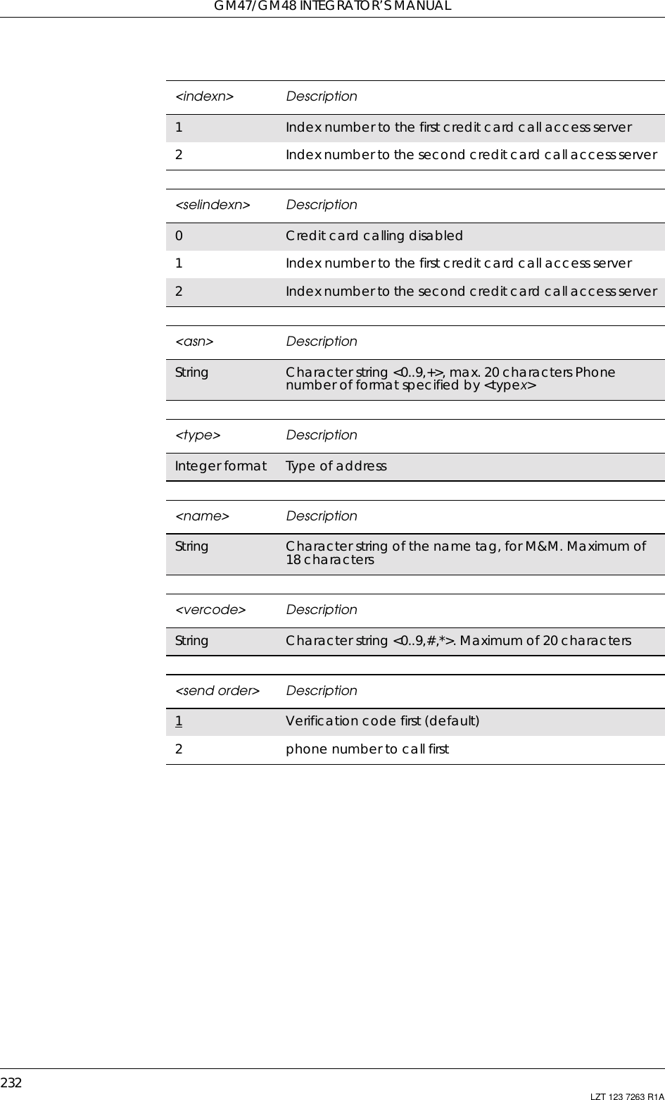
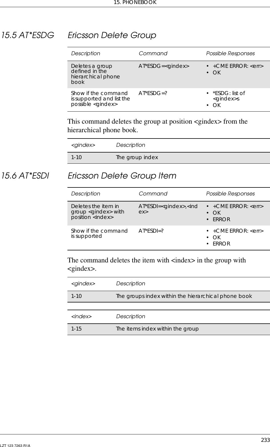
![GM47/GM48 INTEGRATOR’S MANUAL234 LZT 123 7263 R1A15.7 AT*ESGR Ericsson Group ReadThis command lists the groups in the hierarchical phone book.15.8 AT*ESIL Ericsson Silence CommandThis command orders the phone to be in silent mode. When the phoneis in silent mode, all sounds from the MS are prevented. An icon willshow the user that silent mode is active.Description Command Possible ResponsesLists thegroupsdefinedin the hierarchicalphone bookAT*ESGR •*ESGR:<gindex1>,<name1>[<CR><LF><gindex2>,<name2>..]•OK•ERRORShows if the commandis supported AT*ESGR=? OK<gindex> Description1-10 The group index<name> DescriptionString The group nameDescription Command Possible ResponsesSets the MS to silentmode AT*ESIL=[<mode>] •+CMEERROR:<err>•OK•ERRORRead the currentsetting AT*ESIL? •*ESIL:<mode>•+CMEERROR:<err>•OK•ERRORTest if the command issupportedand listthepossible settingsAT*ESIL=? •*ESIL:(listofsupported<mode>s)•+CMEERROR:<err>•OK•ERROR<mode> Description0Silent mode off. Default setting1Silent mode on](https://usermanual.wiki/Sony/6220501-BV.Exhibit-8-Integrators-Manual/User-Guide-247869-Page-234.png)
![15. PHONEBOOK235LZT 123 7263 R1A15.9 AT*ESNU Ericsson Settings NumberThis command sets a <type> number, in the format <number type>, inthe MS.Description Command Possible ResponsesSets a number in theMS AT*ESNU=<type>,<number>[,<number type>]•+CMEERROR:<err>•OK•ERRORTest if the command issupported and showpossible settingsAT*ESNU=? •*ESNU:(listofsupported <type>s)•+CMEERROR:<err>•OK•ERRORRead the currentsetting AT*ESNU? •*ESNU:<type1>,<number1>,<number type1><CR><LF>….*ESNU: <typen>,<numbern>,<number type n>•+CMEERROR:<err>•OK•ERROR<type> Description0Voice L11Voice L22Fax3Data<numbertype> Description129 Default setting when dialling string does not include theinternational access code character ‘+’145 Default setting when dialling string includes theinternational access code character ‘+’<number> Description0-9, + Number](https://usermanual.wiki/Sony/6220501-BV.Exhibit-8-Integrators-Manual/User-Guide-247869-Page-235.png)
![GM47/GM48 INTEGRATOR’S MANUAL236 LZT 123 7263 R1A15.10 AT+CPBF Phonebook FindReturns phone book entries whose alphanumeric field starts with<findtext>.15.11 AT+CPBR Phonebook ReadReturns phone book entries in location number range <index1>...<index2> from the current phone book memory storage selected with+CPBS. If <index2> is left out, only location <index1> is returned.Entry fields returned are location number <indexn>, phone numberstored there <number> (of format <type>) and text <text> associatedwith the number.Description Syntax Possible ResponsesShows the currentsetting +CPBF=<findtext> •+CPBF:<index1>,<number>,<type>,<text>[[...]<CR><LF>+CBPF:<index2>,<number>,<type>,<text>]•+CMEERROR:<err>•OK•ERRORShow if thecommand issupported+CPBF=? • +CPBF: <nlength>,<tlength>•+CMEERROR:<err>•OK•ERROR<findtext > Descriptionstring type Field of maximum length <tlength>; character set asspecified by the select TE character set command, +CSCSDescription Command Possible ResponsesRead phonebook entries +CPBR=<index1>[,<index2>] • +CPBR:<index1>,<number>,<type>,<text>[[,<text_date>,<text_time>]<CR><LF>+CPBR:<index2>,<number>,<type>,<text>[,<text_date>,<text_time>]]• +CME ERROR <err>•OK• ERRORTest if thecommand issupported+CPBR=? • +CPBR: (list of supported<index>s),<nlength>,<tlength>• +CME ERROR <err>•OK• ERROR<indexn> Descriptioninteger type Values in the range of location numbers of phone bookmemory](https://usermanual.wiki/Sony/6220501-BV.Exhibit-8-Integrators-Manual/User-Guide-247869-Page-236.png)
![15. PHONEBOOK237LZT 123 7263 R1A<number> Descriptionstring type Phone number of format <type><type> Description129 ISDN/telephony numbering plan, national/internationalunknown145 ISDN/telephony numbering plan, international number161 ISDN/telephony numbering plan, national number128 - 255 Other values refer to GSM 04.08 [4] section 10.5.4.7<text> Descriptionstring type Field of maximum length <tlength>;character set as specified by the select TE character setcommand, +CSCS.<nlength> Descriptioninteger type Value indicating the maximum length of field <number><tlength > Descriptioninteger type Value indicating the maximum length of field <text>](https://usermanual.wiki/Sony/6220501-BV.Exhibit-8-Integrators-Manual/User-Guide-247869-Page-237.png)
![GM47/GM48 INTEGRATOR’S MANUAL238 LZT 123 7263 R1A15.12 AT+CPBS Phone StorageSelects phone book memory storage <storage>, which is used by otherphone book commands.Description Command Possible ResponsesSet phone bookstorage AT+CPBS=<storage> • +CME ERROR <err>•OK•ERRORRead the currentsetting AT+CPBS? • +CPBS: <storage>[,<used>,<total>]• +CME ERROR <err>•OK•ERRORTest if the command issupported AT+CPBS=? •+CPBS:(listofsupported<storage>s)• +CME ERROR <err>•OK•ERROR<storage> Description“FD” SIM fix-dialing-phone book“LD” SIM Last-dialing-phone book. Not supported“ME” ME phone book“MT” Combined ME and SIM phone books. Not supported“SM” SIM phone book“TA” TA phone book. Not supported“DC” ME dialed calls list (30 entries)“RC” ME received calls list (30 entries)“MC” ME missed calls list (30 entries)“MV” ME Voice Activated Dialing list. Not supported“SG” SMS group list, Ericsson specific. Not supported“CA” Callers allowed, Ericsson specific. Not supported“EN” SIM emergency number (+CPBW is not applicable for thisstorage)“BC” Own business card. Not supported“HP” Hierarchical phone book. Not supported<passwd> DescriptionString Represents the password required when selectingpassword protected <storage>s, for example PIN2 for “FD”](https://usermanual.wiki/Sony/6220501-BV.Exhibit-8-Integrators-Manual/User-Guide-247869-Page-238.png)
![15. PHONEBOOK239LZT 123 7263 R1A15.13 AT+CPBW Phonebook WriteWrites phone book entry in location number <index> in the currentphone book memory storage area, selected with AT+CPBS. If the<number> and <text> parameters are omitted, the entry is deleted. If<index> is omitted but <number> is included, the entry is written to thefirst free location in the phone book.Description Command Possible ResponsesRequest phone bookwrite AT+CPBW=[<index>][,<number>[,<type>[,<text>]]]• +CME ERROR <err>•OK•ERRORShow if the commandis supported AT+CPBW=? •+CPBW:(listofsupported<index>s),<nlength>,(list of supported<type>s),<tlength>• +CME ERROR <err>•OK•ERROR<index> Descriptioninteger type Values in the range of location numbers of phone bookmemory<number> Descriptionstring type Phone number of format <type><type > Descriptioninteger format Type of address octet, default 145 when dialing stringincludes international access code character "+",otherwise 129. (refer to GSM 04.08 [4] subclause 10.5.4.7)129 ISDN/telephony numbering plan, national/internationalunknown. Default if no “+” in sca.145 ISDN/telephony numbering plan, international number.Default if “+” in sca.161 ISDN/telephony numbering plan, national number128-255 Other values refer GSM 04.08 section 10.5.4.7<text > Descriptionstring type Field of maximum length <tlength>;character set as specified by the select TE character setcommand, +CSCS<nlength> Descriptioninteger type Value indicating the maximum length of field <number>](https://usermanual.wiki/Sony/6220501-BV.Exhibit-8-Integrators-Manual/User-Guide-247869-Page-239.png)
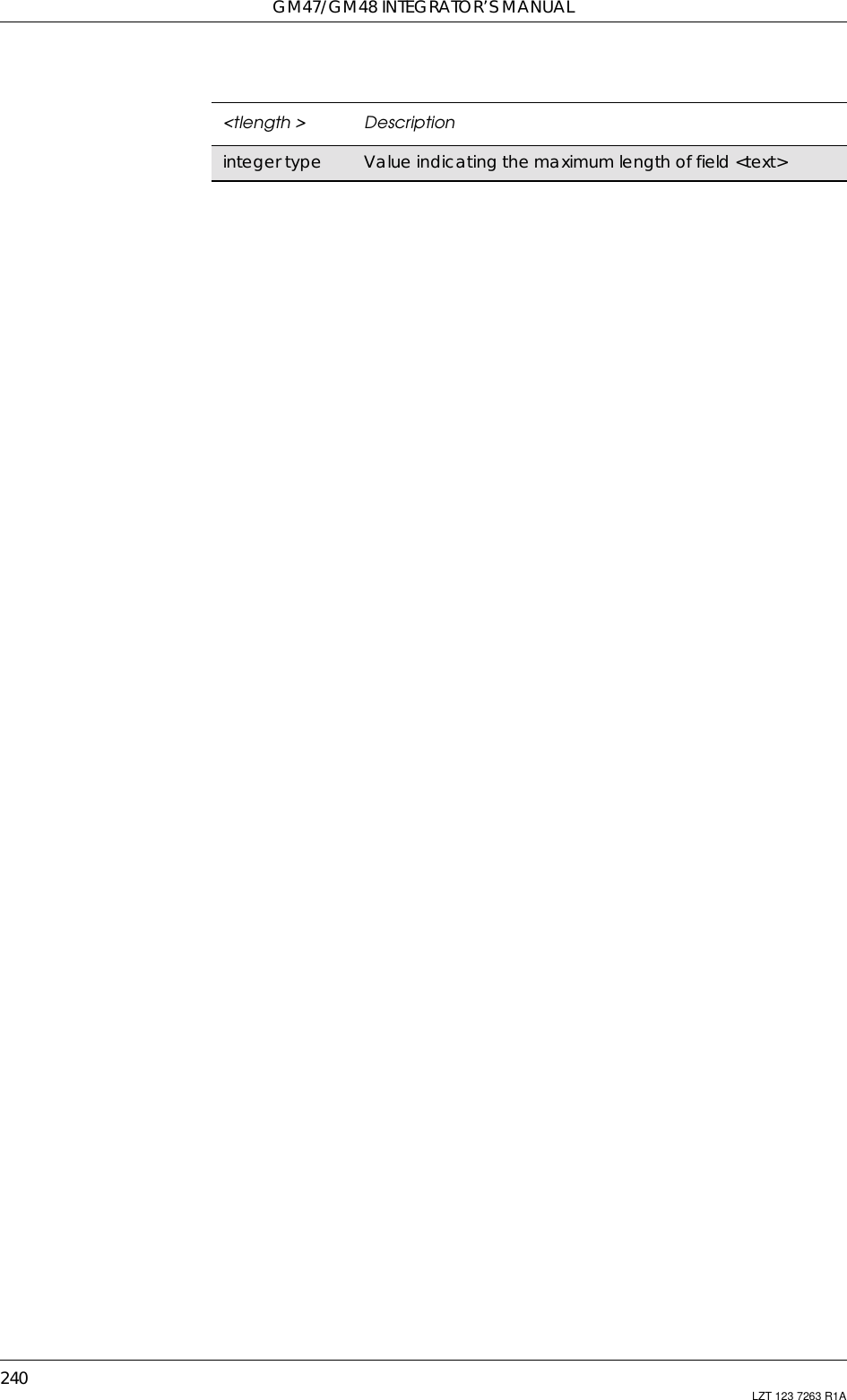
![241LZT 123 7263 R1A16. Short Message Services - Point to Point16.1 AT+CPIN PIN ControlSee 3.27, AT+CPIN PIN Control16.2 AT*ESMA Ericsson Set Message Alert SoundSee 4.15, AT*ESMA Ericsson Set Message Alert Sound16.3 AT+CGSMS Select Service for MO SMS MessagesSee 6.10, AT+CGSMS Select Service for MO SMS Messages16.4 AT+CSCA Service Centre AddressCommon for both PDU and Text ModesUpdates the SMSC address, through which mobile originated SMs aretransmitted. In text mode, the setting is used by send (+CMGS) andwrite (+CMGW) commands. In PDU mode, the setting is used by thesame commands, but only when the length of the SMSC address codedinto <pdu> parameter equals zero. Note that a “+” in front of the numberin <sca> has precedence over the <tosca> parameter, so that a numberstarting with “+” will always be treated as an international number.Description Command Possible ResponsesSet service centreaddress AT+CSCA=<sca>[,<tosca>] •OK•ERRORShow the currentsetting AT+CSCA? •+CSCA:<sca>,<tosca>•OK•ERRORShow if the commandis supported AT+CSCA=? •OK•ERROR<sca> Descriptionstring type GSM 04.11 (3G TS 24.011) RP SC address Address-Valuefield in string format; BCD numbers (or GSM defaultalphabet characters) are converted to characters of thecurrently selected TE character set](https://usermanual.wiki/Sony/6220501-BV.Exhibit-8-Integrators-Manual/User-Guide-247869-Page-241.png)
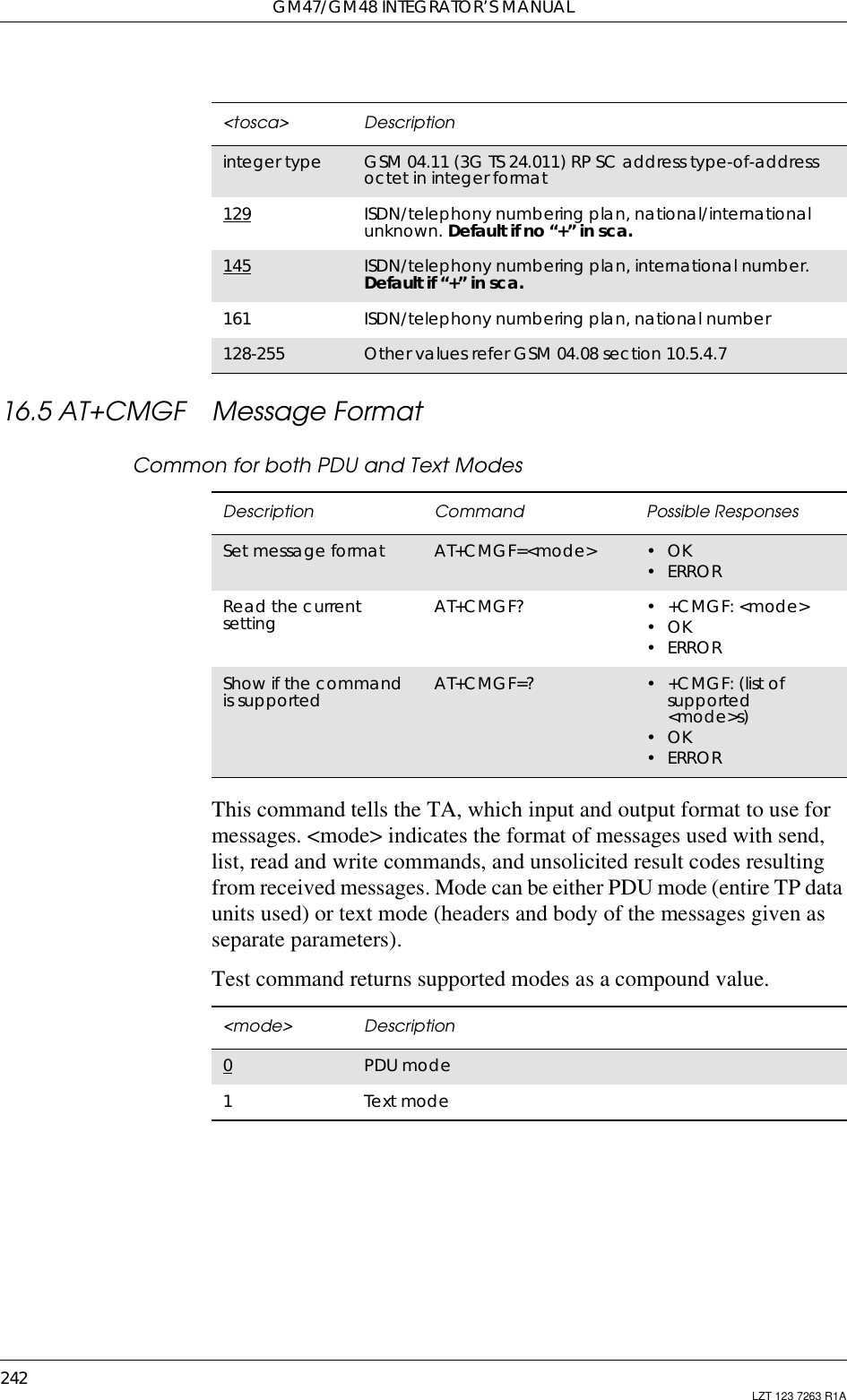
![16. SHORT MESSAGE SERVICES - POINT TO POINT243LZT 123 7263 R1A16.6 AT+CMGW Write Message to MemoryPDU ModeStores a message to memory storage <mem2>. Memory location<index> of the stored message is returned. By default message statuswill be set to 'stored unsent', but parameter <stat> allows other statusvalues to be given. ME/TA manufacturer may choose to use differentdefault <stat> values for different message types. Entering PDU is thesame as specified by the send message command, +CMGS. If writingfails, final result code +CMS ERROR: <err> is returned.Description Command Possible ResponsesWrite message tomemory AT+CMGW=<length>[,<stat>]<CR>PDU is given<ctrl-Z/ESC>•+CMGW:<index>• +CMS ERROR: <err>•OK•ERRORShow if the commandis supported AT+CMGW=? •OK•ERROR<stat> Description0Received unread message (i.e. new message). Notsupported1Received read message. Not supported2Stored unsent message (only applicable to SMs)3Stored sent message (only applicable to SMs). Notsupported16 Template message. Not supported<index> DescriptionInteger type Value in the range of location numbers supported by theassociated memory<length> DescriptionInteger type Value indicating in PDU mode (+CMGF=0), the length ofthe actual TP data unit in octets (i.e. the RP layer SMSCaddress octets are not counted in the length)<pdu> Description... InthecaseofSMS:GSM04.11SCaddressfollowedbyGSM 03.40 TPDU in hexadecimal format: ME/TA convertseach octet of TP data unit into two IRA character longhexadecimal number (e.g. octet with integer value 42 ispresented to TE as two characters 2A (IRA 50 and 65))In the case of CBS: GSM 03.41 TPDU in hexadecimal format](https://usermanual.wiki/Sony/6220501-BV.Exhibit-8-Integrators-Manual/User-Guide-247869-Page-243.png)
![GM47/GM48 INTEGRATOR’S MANUAL244 LZT 123 7263 R1AText ModeStores message (either SMS-DELIVER or SMS-SUBMIT) to memorystorage <mem2>. Memory location <index> of the stored message isreturned. By default message status will be set to ‘stored unsent’, butparameter <stat> allows also other status values to be given. Theentering of text is done as specified in the send message command,+CMGS. If writing fails, final result code +CMS ERROR: <err> isreturned.Note! SMS-COMMANDs and SMS-STATUS-REPORTs cannot be stored intext mode.Description Command Possible ResponsesWrite message tomemory AT+CMGW [=<oa/da>[,<tooa/toda>[,<stat>]]]<CR>Text is entered <ctrl-Z/ESC>•+CMGW:<index>• +CMS ERROR: <err>•OK•ERRORShow if the commandis supported AT+CMGW=? •OK•ERROR<stat> Description0Received unread message (new message). Notsupported1Received read message. Not supported2Stored unsent message (only applicable to SMs)3Stored sent message (only applicable to SMs). Notsupported<oa> DescriptionString type GSM 03.40 TP-Originating-Address Value in string format;BCD numbers (or GSM default alphabet characters) areconverted to characters of the currently selected TEcharacter (refer command +CSCS). Type of address givenby <tooa><da> DescriptionString type GSM 03.40 TP-Destination-Address Value in string format;BCD numbers (or GSM default alphabet characters) areconverted to characters of the currently selected TEcharacter (refer command +CSCS). Type of address givenby <toda><tooa> DescriptionString type GSM 04.11 TP-Originating-Address Type-of-Address octetin integer format (default refer <toda>)](https://usermanual.wiki/Sony/6220501-BV.Exhibit-8-Integrators-Manual/User-Guide-247869-Page-244.png)
![16. SHORT MESSAGE SERVICES - POINT TO POINT245LZT 123 7263 R1A16.7 AT+CMGS Send MessagePDU ModeSends a message from a TE to the network (SMS-SUBMIT). Messagereference value <mr> is returned to the TE on successful messagedelivery. Optionally, when AT+CSMS <service> value is 1 and there isnetwork support, <ackpdu> is returned. Values can be used to identifymessage upon unsolicited delivery status report result code. If sendingfails in a network or an ME error, final result code +CMS ERROR:<err> is returned. This command is abortable.• <length> must indicate the number of octets coded in the TP layerdata unit to be given (i.e. SMSC address octets are excluded).• The TA shall send a four character sequence<CR><LF><greater_than><space> (IRA 13, 10, 62, 32) aftercommand line is terminated with <CR>; after that PDU can be givenfrom TE to ME/TA.• The DCD signal is in the ON state as PDU is given.• The echoing of given characters back from the TA is controlled byV.25ter echo command E.• The PDU shall be hexadecimal format (similarly as specified for<pdu>) and given in one line; ME/TA converts this coding into theactual octets of PDU.• When the length octet of the SMSC address (given in the <pdu>)equals zero, the SMSC address set with command Service CentreAddress +CSCA is used.• Sending can be cancelled by giving <ESC> character (IRA 27).<toda> DescriptionString type GSM 04.11 TP-Destination- Address Type-of-Address octetin integer format (when first character of <da> is +(IRA 43)default is 145, otherwise default is 129<index> DescriptionInteger type Value in the range of location numbers supported by theassociated memoryDescription Command Possible ResponsesSend message AT+CMGS=<length><CR>PDU is given<ctrl-Z/ESC>•+CMGS:<mr>[,<ackpdu>]• +CMS ERROR: <err>•OK•ERRORShow if the commandis supported AT+CMGS=? •OK•ERROR](https://usermanual.wiki/Sony/6220501-BV.Exhibit-8-Integrators-Manual/User-Guide-247869-Page-245.png)
![GM47/GM48 INTEGRATOR’S MANUAL246 LZT 123 7263 R1A• <ctrl-Z> (IRA 26) must be used to indicate the ending of PDU.Text ModeSends a message from a TE to the network (SMS-SUBMIT). Messagereference value <mr> is returned to the TE on successful messagedelivery. Optionally, when AT+CSMS <service> value is 1 and there isnetwork support, <scts> is returned. Values can be used to identifymessage upon unsolicited delivery status report result code. If sendingfails in a network or an ME error, final result code +CMS ERROR:<err> is returned. This command is abortable.• The entered text (GSM 03.40 TP-Data-Unit) is sent to address <da>and all current settings (refer Set Text Mode Parameters +CSMP andService Centre Address +CSCA) are used to construct the actualPDU in the ME/TA.• The TA shall send a four character sequence<CR><LF><greater_than><space> (IRA 13, 10, 62, 32) after thecommand line is terminated with <CR>; after that text can beentered from the TE to the ME/TA.• The DCD signal is in the ON state as text is entered.• The echoing of entered characters back from the TA is controlled byV.25ter echo command E.<mr> DescriptionInteger type GSM 03.40 TP-Message-Reference in integer format<length> DescriptionInteger type Value indicating in PDU mode (+CMGF=0), the length ofthe actual TP data unit in octets (i.e. the RP layer SMSCaddress octets are not counted in the length)<ackpdu> Description... GSM 03.40 RP-User-Data element of RP-ACK PDU; format issame as for <pdu> in case of SMS, but without GSM 04.11SC address field and parameter shall be bounded bydouble quote characters like a normal string typeparameterDescription Command Possible ResponsesSend message AT+CMGS=<da>[,<toda>] <CR>Text is entered<ctrl-Z/ESC>•+CMGS:<mr>[,<scts>]• +CMS ERROR: <err>•OK•ERRORShow if the commandis supported AT+CMGS=? •OK•ERROR](https://usermanual.wiki/Sony/6220501-BV.Exhibit-8-Integrators-Manual/User-Guide-247869-Page-246.png)
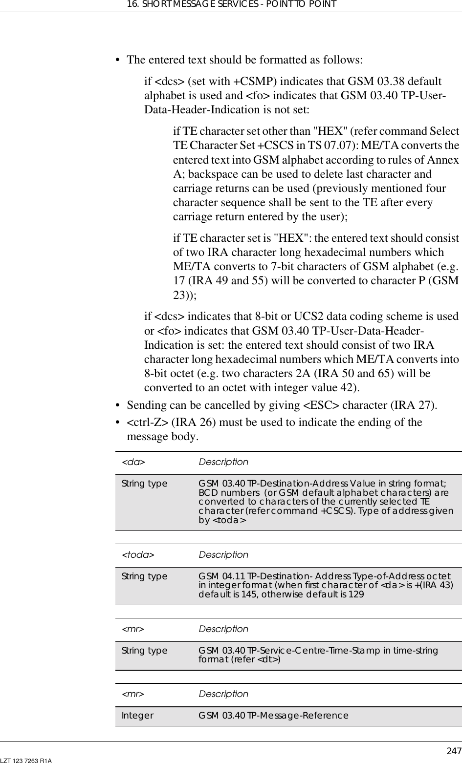
![GM47/GM48 INTEGRATOR’S MANUAL248 LZT 123 7263 R1A16.8 AT+CMSS Send From StoragePDU modeSends message with location value <index> from message storage<mem2> to the network (SMS-SUBMIT or SMS-COMMAND).Reference value <mr> is returned to the TE on successful messagedelivery. If sending fails in a network or an ME error, final result code+CMS ERROR: <err> is returned. This command is abortable.Text ModeSends message with location value <index> from message storage<mem2> to the network (SMS-SUBMIT or SMS-COMMAND).Reference value <mr> is returned to the TE on successful messagedelivery. Optionally, when +CSMS <service> value is 1 and networksupports, <scts> is returned. If sending fails in a network or an MEerror, final result code +CMS ERROR: <err> is returned. Thiscommand is abortable.Description Command Possible ResponsesSend from storage AT+CMSS=<index> •+CMSS:<mr>• +CMS ERROR: <err>•OK•ERRORShow if the commandis supported AT+CMSS=? •OK•ERROR<index> DescriptionInteger type Valueintherangeoflocationnumberssupportedbytheassociated memory<mr> DescriptionInteger type GSM 03.40 TP-Message-Reference in integer formatDescription Command Possible ResponsesSend from storage AT+CMSS=<index>[,<da> [,<toda>]] • +CMSS: <mr> [,<scts>]• +CMS ERROR: <err>•OK•ERRORShow if thecommand issupportedAT+CMSS=? •OK•ERROR<index> DescriptionInteger type Valueintherangeoflocationnumberssupportedbytheassociated memory](https://usermanual.wiki/Sony/6220501-BV.Exhibit-8-Integrators-Manual/User-Guide-247869-Page-248.png)
![16. SHORT MESSAGE SERVICES - POINT TO POINT249LZT 123 7263 R1A16.9 AT+CMGC Send CommandPDU ModeSends a command message from a TE to the network (SMS-COMMAND). The entering of PDU is as specified in the send messagecommand, +CMGS. Message reference value <mr> is returned to theTE on successful message delivery. Optionally (when +CSMS<service> value is 1 and network supports) <ackpdu> is returned.Values can be used to identify message upon unsolicited delivery statusreport result code. If sending fails in a network or an ME error, finalresult code +CMS ERROR: <err> is returned. This command isabortable.<da> DescriptionString type GSM 03.40 TP-Destination-Address Value in string format;BCD numbers (or GSM default alphabet characters) areconverted to characters of the currently selected TEcharacter(refercommand+CSCS).Typeofaddressgivenby <toda><toda> DescriptionString type GSM 04.11 TP-Destination- Address Type-of-Address octetin integer format (when first character of <da> is +(IRA 43)default is 145, otherwise default is 129<scts> DescriptionString type GSM 03.40 TP-Service-Centre-Time-Stamp in time-stringformat (refer <dt>)<mr> DescriptionInteger type GSM 03.40 TP-Message-Reference in integer formatDescription Command Possible ResponsesSend commandmessage AT+CMGC=<length><CR><pdu><ctrl-Z/ESC> •ifPDUmode(+CMGF=0) andsending successful:+CMGC:<mr>[,<ackpdu>]•ifsendingfails:+CMS ERROR: <err>•OK•ERRORShow if thecommand issupportedAT+CMGC=? •OK•ERROR](https://usermanual.wiki/Sony/6220501-BV.Exhibit-8-Integrators-Manual/User-Guide-247869-Page-249.png)
![GM47/GM48 INTEGRATOR’S MANUAL250 LZT 123 7263 R1AText ModeSends a command message from a TE to the network (SMS-COMMAND). The entering of text is as specified in the send messagecommand, +CMGS, but the format is fixed to be a sequence of two IRAcharacter long hexadecimal numbers, which the ME/TA converts into8-bit octets (refer to +CMGS). Message reference value <mr> isreturned to the TE on successful message delivery. Optionally, when+CSMS <service> value is 1 and there is network support, <scts> isreturned. Values can be used to identify message upon unsolicited<length> DescriptionInteger type Value indicating in PDU mode (+CMGF=0), the length ofthe actual TP data unit in octets (i.e. the RP layer SMSCaddress octets are not counted in the length)<pdu> DescriptionString InthecaseofSMS:GSM04.11SCaddressfollowedbyGSM 03.40 TPDU in hexadecimal format: ME/TA convertseach octet of TP data unit into two IRA character longhexadecimal number (e.g. octet with integer value 42 ispresented to TE as two characters 2A (IRA 50 and 65))In the case of CBS: GSM 03.41 TPDU in hexadecimal format<mr> DescriptionInteger type GSM 03.40 TP-Message-Reference in integer format<ackpdu> DescriptionString GSM 03.40 RP-User-Data element of RP-ACK PDU; format issame as for <pdu> in case of SMS, but without GSM 04.11SC address field and parameter shall be bounded bydouble quote characters like a normal string typeparameterDescription Command Possible ResponsesSend commandmessage AT+CMGC=<fo>,<ct>[,<pid>[,<mn>[,<da>[,<toda>]]]]<CR>Text is entered<ctrl-Z/ESC>•ifPDUmode(+CMGF=1) andsending successful:+CMGC:<mr>[,<scts>]•ifsendingfails:+CMS ERROR: <err>•OK•ERRORShow if thecommands issupportedAT+CMGC=? •OK•ERROR](https://usermanual.wiki/Sony/6220501-BV.Exhibit-8-Integrators-Manual/User-Guide-247869-Page-250.png)
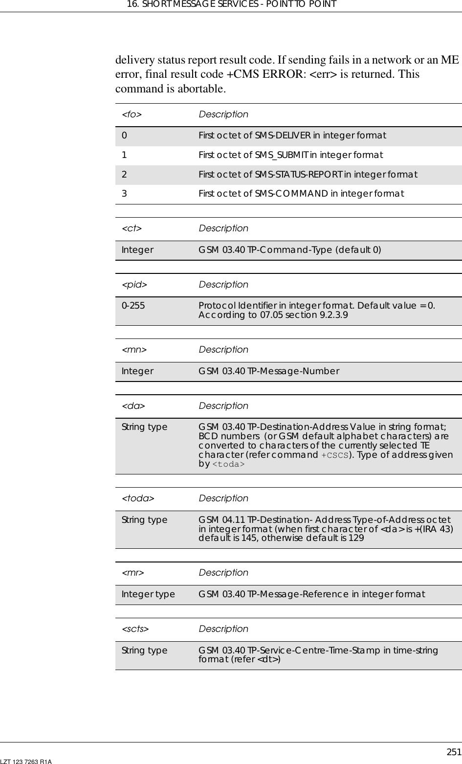
![GM47/GM48 INTEGRATOR’S MANUAL252 LZT 123 7263 R1A16.10 AT+CPMS Preferred Message StorageCommon for both PDU and Text ModesSelects memory storage <mem1>, <mem2> and <mem3> to be used forreading, writing, etc. If chosen storage is not appropriate for the ME(but is supported by the TA), final result code +CMS ERROR: <err>shall be returned.Test command returns lists of memory storage supported by the TA.Description Command Possible ResponsesSet preferredmessage storage AT+CPMS=<mem1>[,<mem2>][,<mem3>]•+CPMS:<used1>,<total1>,<used2>,<total2>,<used3>,<total3>• +CMS ERROR: <err>•OK•ERRORRead the command AT+CPMS? •+CPMS:<mem1>,<used1>,<total1,<mem2>,<used2>,<total2,<mem3>,<used3>,<total3>• +CMS ERROR: <err>•OK•ERRORShow if thecommand issupportedAT+CPMS=? • +CPMS: (list of supported<mem1>s),(list ofsupported <mem2>s),(listof supported <mem3>s)•OK•ERROR<mem1> Descriptionstring type Memory from which messages are read and deleted(commands List Messages +CMGL, Read Message+CMGR and Delete Message +CMGD)“ME” ME message storage“SM” SIM message storage<mem2> Descriptionstring type Memory to which writing and sending operations aremade (commands Send Message from Storage +CMSSand Write Message to Memory +CMGW)“ME” ME message storage“SM” SIM message storage](https://usermanual.wiki/Sony/6220501-BV.Exhibit-8-Integrators-Manual/User-Guide-247869-Page-252.png)
![16. SHORT MESSAGE SERVICES - POINT TO POINT253LZT 123 7263 R1A16.11 AT+CNMI New Message Indications to TEPDU ModeSelects the procedure for the way in which new messages received fromthe network, are indicated to the TE when it is active, e.g. DTR signalis ON. If the TE is inactive (DTR signal is OFF), message receiving iscarried out as specified in GSM 03.38 (3G TS 23.038).<mem3> Descriptionstring type Memory to which received SMs are preferred to be stored(unless forwarded directly to TE). Received CBMs arealways stored in “BM” (or some manufacturer specificstorage) unless directly forwarded to TE“ME” ME message storage“SM” SIM message storage<used1>,<used2>,<used3> Descriptioninteger type Total number of messages currently in<mem1>, <mem2> and <mem3> respectively<total1>,<total2> ,<total3> Descriptioninteger type Total number of message locations in<mem1>, <mem2> and <mem3> respectivelyDescription Command Possible ResponsesSet new messageindication to TE AT+CNMI=[<mode>[,<mt>[,<bm>[,<ds>[,<bfr>]]]]]• +CMS ERROR: <err>•OK•ERRORShows the currentsetting AT+CNMI? •+CNMI:<mode>,<mt>,<bm>,<ds>,<bfr>•OK•ERRORShow if thecommand issupportedAT+CNMI=? •+CNMI:(list of supported <mode>s),(list of supported <mt>s),(list of supported <bm>s),(list of supported <ds>s),(list of supported <bfr>s)•OK•ERROR](https://usermanual.wiki/Sony/6220501-BV.Exhibit-8-Integrators-Manual/User-Guide-247869-Page-253.png)
![GM47/GM48 INTEGRATOR’S MANUAL254 LZT 123 7263 R1AIf the command fails and the error is related to mobile equipment ornetwork, the final result code CMS ERROR: <err> is returned.<mode> Description3Forward unsolicited result codes directly to the TE. TA-TElink specific inband technique used to embed resultcodes and data when TA is in on-line data mode<mt> Description0No SMS-DELIVER indications are routed to the TE.No class, Class 0, class 1 and class 3 use <mem3> aspreferred storage. Class 2 messages shall be stored in theSIM. If it this is not possible then the MS shall send an errormessage accordingly to GSM 03.381SMS-DELIVER is stored into ME/TA and the indication of thememory location is routed to the TE using unsolicited resultcode:+CMTI: <mem>,<index>2Class 0, class 1, and class 3 SMS-DELIVERs are routeddirectlytotheTEusingtheunsolicitedresultcodebutnotstored in ME/TA:+CMT:[<alpha >], <length><CR><LF><pdu> (PDU modeenabled)Class 2 data coding scheme result in indication as definedin <mt>=13Class 3 SMS-DELIVERs are routed directly to TE usingunsolicited result codes +CMT: <length><CR><LF><pdu>.Class 3 SMS-DELIVER is not stored in ME/TA. Messages ofother data coding schemes result in indication as definedin <mt>=1<bm> Description0Store message to “BM” (or some manufacturer specificmemory). No CBM indications are routed to the TE2New CBMs are routed directly to the TE using unsolicitedresult code:+CBM: <length><CR><LF><pdu> (PDU mode enabled).New CBMs are not stored in CBM memory<ds> Description0No SMS-STATUS-REPORTs are routed to the TE. SMS-STATUS-REPORT is stored in ME/TA1SMS-STATUS-REPORTs are routed to the TE using unsolicitedresultcode:+CDS:<length><CR><LF><pdu>(PDUmode enabled). SMS-STATUS-REPORT is not stored in ME/TA2SMS-STATUS-REPORTs are routed to the TE using unsolicitedresultcode:+CDSI:<mem><index>(PDUmodeenabled).SMS-STATUS-REPORT is stored in ME/TA](https://usermanual.wiki/Sony/6220501-BV.Exhibit-8-Integrators-Manual/User-Guide-247869-Page-254.png)
![16. SHORT MESSAGE SERVICES - POINT TO POINT255LZT 123 7263 R1AUnsolicited Result codes:+CMT: <length><CR><LF><pdu>+CMTI: <mem>,<index>+CBM: <length><CR><LF><pdu>+CDS: <length><CR><LF><pdu>+CDSI: <mem><index>Text ModeSelects the procedure for the way in which new messages received fromthe network, are indicated to the TE when it is active, e.g. DTR signalis ON. If TE is inactive (DTR signal is OFF), message receiving iscarried out as specified in GSM 03.38 (3G TS 23.038).If the command fails and the error is related to mobile equipment ornetwork, the final result code CMS ERROR: <err> is returned.<bfr> Description0TA buffer of unsolicited result codes defined within thiscommand is flushed to the TE when <mode> 1..2 isentered (OK response shall be given before flushing thecodes). Not supportedDescription Command Possible ResponsesSet new messageindication to TE AT+CNMI=[<mode>[,<mt>[,<bm>[,<ds>[,<bfr>]]]]]• +CMS ERROR: <err>•OK•ERRORShows the currentsetting AT+CNMI? •+CNMI:<mode>,<mt>,<bm>,<ds>,<bfr>•OK•ERRORShow if thecommand issupportedAT+CNMI=? •+CNMI:(list of supported <mode>s),(list of supported <mt>s),(list of supported <bm>s),(list of supported <ds>s),(list of supported <bfr>s)•OK•ERROR<mode> Description3Forward unsolicited result codes directly to the TE. TA-TElink specific inband technique used to embed resultcodes and data when TA is in on-line data mode](https://usermanual.wiki/Sony/6220501-BV.Exhibit-8-Integrators-Manual/User-Guide-247869-Page-255.png)
![GM47/GM48 INTEGRATOR’S MANUAL256 LZT 123 7263 R1A<mt> Description0No SMS-DELIVER indications are routed to the TE.No class, Class 0, class 1 and class 3 use <mem3> aspreferred storage. Class 2 messages shall be stored in theSIM. If it this is not possible then the MS shall send an errormessage accordingly to GSM 03.381SMS-DELIVER is stored into ME/TA and the indication of thememory location is routed to the TE using unsolicited resultcode:+CMTI: <mem>,<index>2Class 0, class 1, and class 3 SMS-DELIVERs are routeddirectlytotheTEusingtheunsolicitedresultcode:+CMT:<oa>, [<alpha>, <scts> [ ,<tooa>,<fo>,<pid>,<dcs>,<sca>,<tosca>,<length>]<CR><LF><data> (text modeenabled). About parameters in italics, refer to the showtext mode command, +CSDH3Class 3 SMS-DELIVERs are routed directly to TE usingunsolicited result codes +CMT:<oa>, [<alpha>, <scts> [,<tooa>,<fo>,<pid>,<dcs>,<sca>,<tosca>,<length>]<CR><LF><data> (Text Mode enabled). About parameters initalics, refer to the show text mode command, +CSDH.Messages of other data coding schemes result inindication as defined in <mt>=1<bm> Description0Store message to “BM” (or some manufacturer specificmemory). No CBM indications are routed to the TE2New CBMs are routed directly to the TE using unsolicitedresult code:+CBM:<sn>,<mid>,<dcs>,<page>,<pages><CR><LF><data>(Text mode enabled)<ds> Description0No SMS-STATUS-REPORTs are routed to the TE1SMS-STATUS-REPORTs are routed to the TE using unsolicitedresult code: : +CDS:<fo>,<mr>,[<ra>],[<tora>],<scts>,<dt>,<st> (Text modeenabled). SMS-STATUS-REPORT is not stored in ME/TA2SMS-STATUS-REPORTs are routed to the TE using unsolicitedresult code: +CDSI: < mem><index> (Text mode enabled).SMS-STATUS-REPORT is stored in ME/TA<bfr> Description0TA buffer of unsolicited result codes defined within thiscommand is flushed to the TE when <mode> 1...2 isentered (OK response shall be given before flushing thecodes). Not supported](https://usermanual.wiki/Sony/6220501-BV.Exhibit-8-Integrators-Manual/User-Guide-247869-Page-256.png)
![16. SHORT MESSAGE SERVICES - POINT TO POINT257LZT 123 7263 R1AUnsolicited Result codes:+CMT:<oa>, [<alpha>, <scts>[,<tooa>,<fo>,<pid>,<dcs>,<sca>,<tosca>,<length>]<CR><LF><data> (Text Mode enabled). Refer to the show text mode command,+CSDH for information on the parameters in italics.+CMTI: <mem>,<index>+CBM: <sn>,<mid>,<dcs>,<page>,<pages><CR><LF><data>+CDS: <fo>,<mr>,[<ra>],[<tora>],<scts>,<dt>,<st>+CDSI: <mem><index>16.12 AT+CMGR Read MessagePDU ModeReturns message with location value <index> from preferred messagestorage <mem1> to the TE. Status of the message and entire messagedata unit <pdu> is returned. If status of the message is ‘receivedunread’, status in the storage changes to ‘received read’. If reading fails,final result code +CMS ERROR: <err> is returned.Description Command Possible ResponsesReadmessage AT+CMGR=<index> •+CMGR: <stat>,[<alpha>],<length>]<CR><LF><pdu>•+CMSERROR:<err>•OK• ERRORShow if thecommand issupportedAT+CMGR=? •OK• ERROR<stat> Description0Received unread message (i.e. new message)1Received read message2Stored unsent message (only applicable to SMs)3Stored sent message (only applicable to SMs)16 Template message. Not supported<index> DescriptionInteger type Value in the range of location numbers supported by theassociated memory<alpha> DescriptionString type Manufacturing specific. Should be left empty but notomitted](https://usermanual.wiki/Sony/6220501-BV.Exhibit-8-Integrators-Manual/User-Guide-247869-Page-257.png)
![GM47/GM48 INTEGRATOR’S MANUAL258 LZT 123 7263 R1AText ModeReturns messages with location index <index> from message storage<mem1> to the TE. About text mode parameters in Italics, refercommand Show Text Mode Parameters (+CSDH), If the status of themessage is ‘received unread’, status in the storage changes to ‘receivedread’. If listing fails final result code +CMS ERROR: <err> is returned.<length> DescriptionInteger type Value indicating in PDU mode (+CMGF=0), the length ofthe actual TP data unit in octets (i.e. the RP layer SMSCaddress octets are not counted in the length)<pdu> DescriptionInthecaseofSMS:GSM04.11SCaddressfollowedbyGSM 03.40 TPDU in hexadecimal format: ME/TA convertseach octet of TP data unit into two IRA character longhexadecimal number (e.g. octet with integer value 42 ispresented to TE as two characters 2A (IRA 50 and 65))In the case of CBS: GSM 03.41 TPDU in hexadecimal formatDescription Command Possible ResponsesReadmessage AT+CMGR=<index> •if text mode (+CMGF=1), commandsuccessful and SMS-DELIVER:+CMGR:<stat>,<oa>,[<alpha>],<scts>,[<tooa>,<fo>,<pid>,<dcs>,<sca>,<tosca>,<length>]<CR><LF><data>•if text mode (+CMGF=1), commandsuccessful and SMS-SUBMIT:+CMGR:<stat>,<da>,[<alpha>],[<toda>,<fo>,<pid>,<dcs>,[<vp>],<sca>,<tosca>,<length>]<CR><LF><data>•if text mode (+CMGF=1), commandsuccessful and SMS-STATUS-REPORT:+CMGR:<stat>,<fo>,<mr>,[<ra>],[<tora>],<scts>,<dt>,<st>•if text mode (+CMGF=1), commandsuccessful and SMS-COMMAND:+CMGR:<stat>,<fo>,<ct>[,<pid>,[<mn>],[<da>],[<toda>],<length><CR><LF><cdata>]•if text mode (+CMGF=1), commandsuccessful and CBM storage:+CMGR:<stat>,<sn>,<mid>,<dcs>,<page>,<pages><CR><LF><data>•+CMSERROR:<err>•OK• ERRORShow if thecommand issupportedAT+CMGR=? •OK• ERROR<index> DescriptionInteger type Valueintherangeoflocationnumberssupportedby<mem1>](https://usermanual.wiki/Sony/6220501-BV.Exhibit-8-Integrators-Manual/User-Guide-247869-Page-258.png)
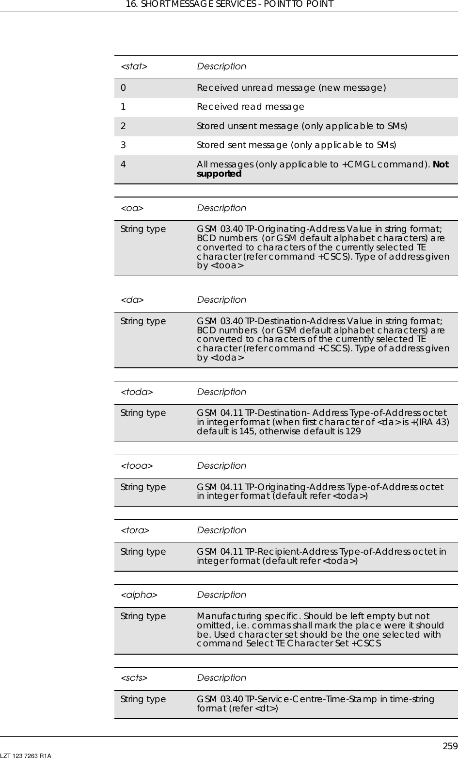
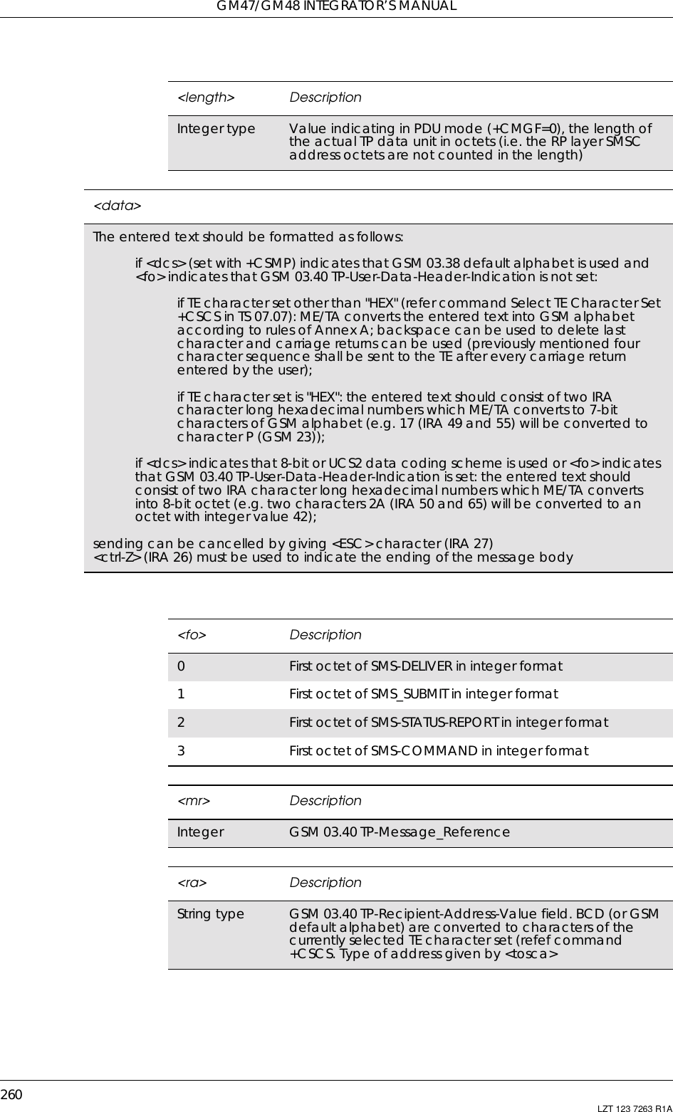
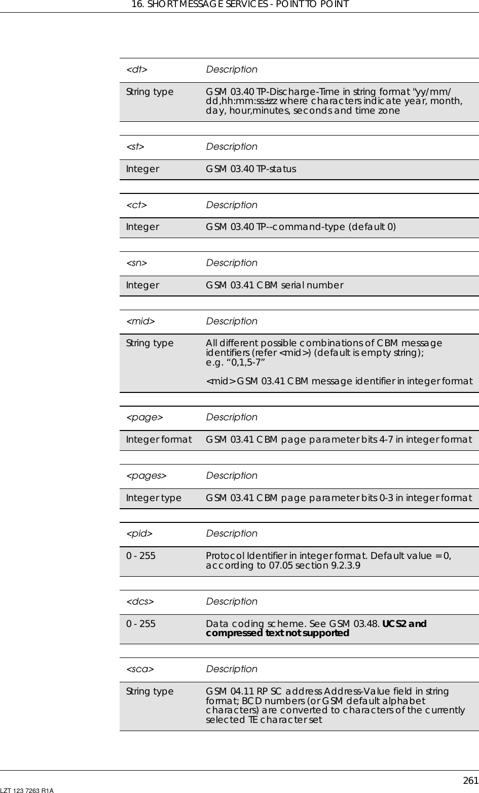
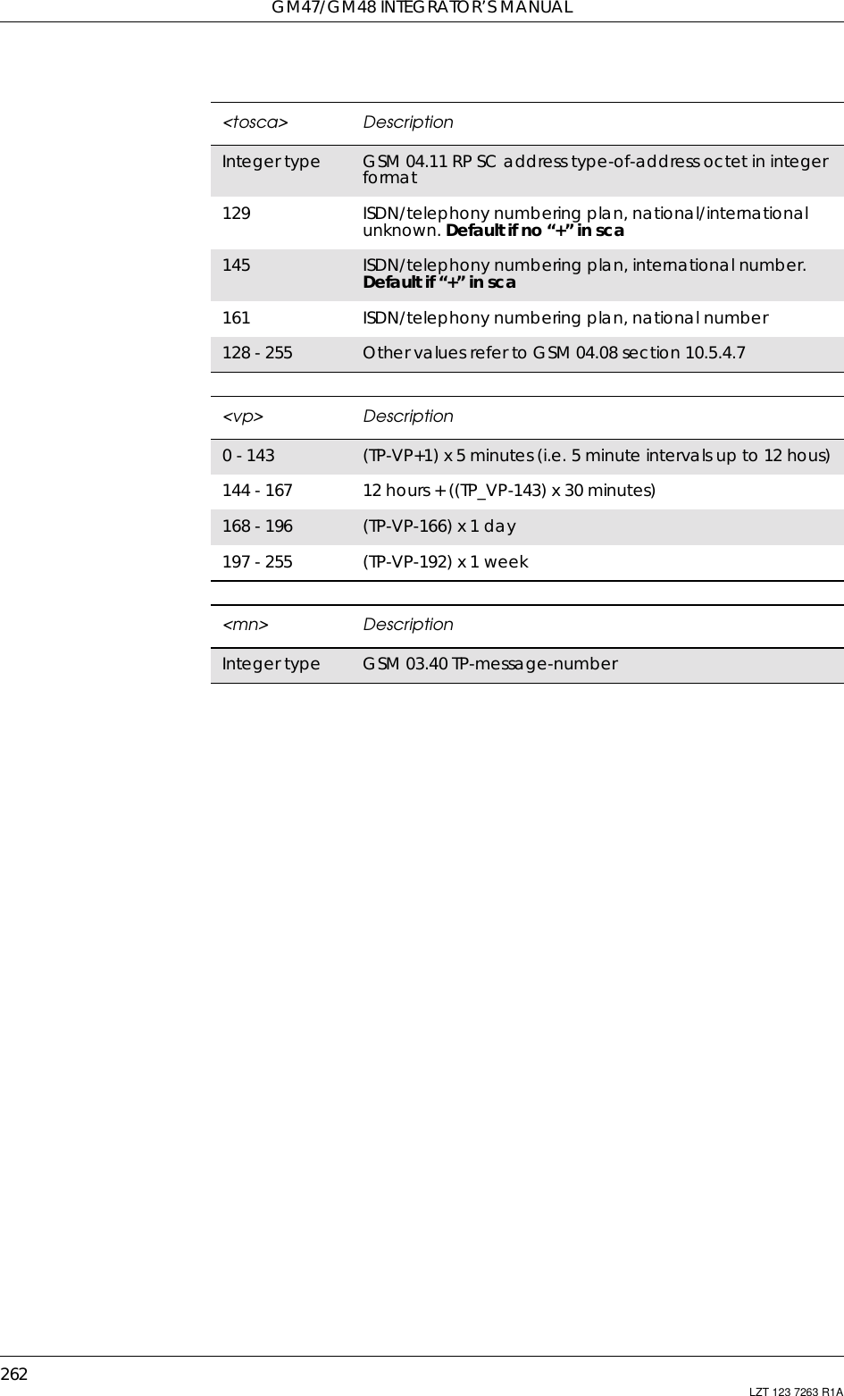
![16. SHORT MESSAGE SERVICES - POINT TO POINT263LZT 123 7263 R1A16.13 AT+CMGL List MessagePDU ModeNote! Returns messages with status value <stat> from preferred messagestorage <mem1> to the TE. Entire data units <pdu> are returned. Ifstatus of the message is ‘received unread’, status in the storage changesto ‘received read’. If listing fails, final result code +CMS ERROR:<err> is returned.Description Command Possible ResponsesList message AT+CMGL[=<stat>] •+CMGL:<index>,<stat>,[<alpha>],<length><CR><LF><pdu>[<CR><LF>+CMGL:<index>,<stat>,[<alpha>],<length><CR><LF><pdu>[…]]• +CMS ERROR: <err>•OK•ERRORShow if thecommand issupportedAT+CMGL=? • +CMGL: (list of supported <stat>s)•OK•ERROR<stat> Description0Received unread message (i.e. new message)1Received read message2Stored unsent message (only applicable to SMs)3Stored sent message (only applicable to SMs)4All messages (only applicable to +CMGL command)16 Template message. Not supported<index> DescriptionInteger type Value in the range of location numbers supported by theassociated memory<alpha> DescriptionString type Manufacturing specific. Should be left empty but notomitted<length> DescriptionInteger type Value indicating in PDU mode (+CMGF=0), the length ofthe actual TP data unit in octets (i.e. the RP layer SMSCaddress octets are not counted in the length)](https://usermanual.wiki/Sony/6220501-BV.Exhibit-8-Integrators-Manual/User-Guide-247869-Page-263.png)
![GM47/GM48 INTEGRATOR’S MANUAL264 LZT 123 7263 R1AText ModeReturns messages with status value <stat> from message storage<mem1> to the TE. About text mode parameters in Italics, refercommand Show Text Mode Parameters (+CSDH). If the status, of themessage is ‘received unread’, status in the storage changes to ‘receivedread’. If listing fails final result code +CMS ERROR: <err> is returned.<pdu> DescriptionInthecaseofSMS:GSM04.11SCaddressfollowedbyGSM 03.40 TPDU in hexadecimal format: ME/TA convertseach octet of TP data unit into two IRA character longhexadecimal number (e.g. octet with integer value 42 ispresented to TE as two characters 2A (IRA 50 and 65))In the case of CBS: GSM 03.41 TPDU in hexadecimal formatDescription Command Possible ResponsesList message AT+CMGL[=<stat>] •if text mode (+CMGF=1), commandsuccessful and SMS-SUBMITs and/orSMS-DELIVERs:+CMGL: <index1>,<stat>,<oa/da>,[<alpha>],[<scts>][,<tooa/toda>,<length>]<CR><LF><data>[<CR><LF>+CMGL: <index2>,<stat>,<oa/da>,[<alpha>],[<scts>][,<tooa/toda>,<length>]<CR><LF><data>[…]]•if text mode (+CMGF=1), commandsuccessful and SMS-STATUS-REPORTs:+CMGL:<index1>,<stat>,<fo>,<mr>,[<ra>],[<tora>],<scts>,<dt>,<st>[<CR><LF>+CMGL:<index2>,<stat>,<fo>,<mr>,[<ra>],[<tora>],<scts>,<dt>,<st>[…]]•if text mode (+CMGF=1), commandsuccessful and SMS-COMMANDs:+CMGL:<index>,<stat>,<fo>,<ct>[<CR><LF>+CMGL:<index>,<stat>,<fo>,<ct>[…]]•if text mode (+CMGF=1), commandsuccessful and CBM storage:+CMGL:<index>,<stat>,<sn>,<mid>,<page>,<pages>,<CR><LF><data>[<CR><LF>+CMGL:+CMGL:<index>,<stat>,<sn>,<mid>,<page>,<pages><CR><LF><data>[…]]•otherwise:+CMS ERROR: <err>•OK• ERRORShow if thecommand issupportedAT+CMGL=? • +CMGL: (list of supported <stat>s)•OK• ERROR<index> DescriptionInteger type Valueintherangeoflocationnumberssupportedby<mem1>](https://usermanual.wiki/Sony/6220501-BV.Exhibit-8-Integrators-Manual/User-Guide-247869-Page-264.png)
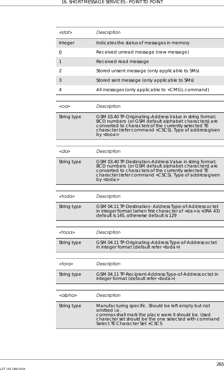
![GM47/GM48 INTEGRATOR’S MANUAL266 LZT 123 7263 R1A16.14 AT+CMGD Delete MessageCommon for both PDU and Text modesDeletes message from preferred message storage <mem1> location<index>. If <delflag> is present and not set to 0 then the ME will ignore<index> and follow the rules for <delflag> shown below. If deletingfails, final result code +CMS ERROR: <err> is returned. Test commandshows the valid memory locations and optionally the supported valuesof <delflag>.<scts> DescriptionString type GSM 03.40 TP-service-centre-time-stamp in time-stringformat (refer <dt>)<length> DescriptionInteger type Value indicating in PDU mode (+CMGF=0), the length ofthe actual TP data unit in octets (i.e. the RP layer SMSCaddress octets are not counted in the length)Description Command Possible ResponsesDelete message AT+CMGD=<index>[,<delflag>] • +CMS ERROR: <err>•OK•ERRORShow if the commandis supported AT+CMGD=? •OK•ERROR<index> DescriptionInteger type Indicates multiple messages delation request as follows0Delete the message specified in <index>1Delete all read messages from preferred messagestorage, leaving unread messages and stored mobileoriginated messages (whether sent or not) untouched2Delete all read messages from preferred message storageandsentmobileoriginatedmessages,leavingunreadmessages and unsent mobile originated messagesuntouched3Delete all read messages from preferred messagestorage, sent and unsent mobile originated messagesleaving unread messages untouched4Delete all messages from preferred message storageincluding unread messages<index> DescriptionInteger type Valueintherangeoflocationnumberssupportedbytheassociated memory](https://usermanual.wiki/Sony/6220501-BV.Exhibit-8-Integrators-Manual/User-Guide-247869-Page-266.png)
![16. SHORT MESSAGE SERVICES - POINT TO POINT267LZT 123 7263 R1A16.15 AT+CSDH Show Text Mode ParametersOnly Applicable to Text ModeControls whether detailed header information is shown in text moderesult codes.16.16 AT+CSMP Set Text Mode ParametersOnly Applicable to Text ModeUsed to select values for additional parameters needed when SM issent to the network or placed in a storage when text format messagemode is selected. It is possible to set the validity period starting fromwhen the SM is received by the SMSC (<vp> is in range 0… 255). The<pid> parameter identifies the higher protocol being used or indicatesDescription Command Possible ResponsesSet the show textmode AT+CSDH=[<show>] •+CMEERROR:<err>•OKDisplay current settings AT+CSDH? •+CSDH:<show>•+CMEERROR:<err>Show if the commandis supported AT+CSDH=? • +CSDH: (list ofsupported <show>s)•OK•+CMEERROR:<err><show> Description0Do not show header values defined in commandsAT+CSCA and AT+CSMP (<sca>, <tosca>, <fo>, <vp>,<pid> and <dcs>) nor <length>, <toda> or <tooa> in+CMT,+CMGL,+CMGRresultcodesforSMS-DELIVERsandSMS-SUBMITs in text mode; for SMS-COMMANDs in +CMGRresult code, do not show <pid>, <mn>, <da>, <toda>,<length> or <cdata>1Show the values in result codesDescription Command Possible ResponsesSet the text modeparameters AT+CSMP=[<fo> [,<vp>[,<pid>[,<dcs>]]]]• +CME ERROR: <err>•OK• ERRORDisplay currentsettings AT+CSMP? • +CSMP: <fo>,<vp>,<pid>,<dcs>• +CME ERROR: <err>Show if thecommand issupportedAT+CSMP=? • +CSMP: (List of supported <fo>s),(list of supported <vp>s), (list ofsupported <pid>s), (list ofsupported <dcs>s)• +CME ERROR: <err>•OK• ERROR](https://usermanual.wiki/Sony/6220501-BV.Exhibit-8-Integrators-Manual/User-Guide-247869-Page-267.png)
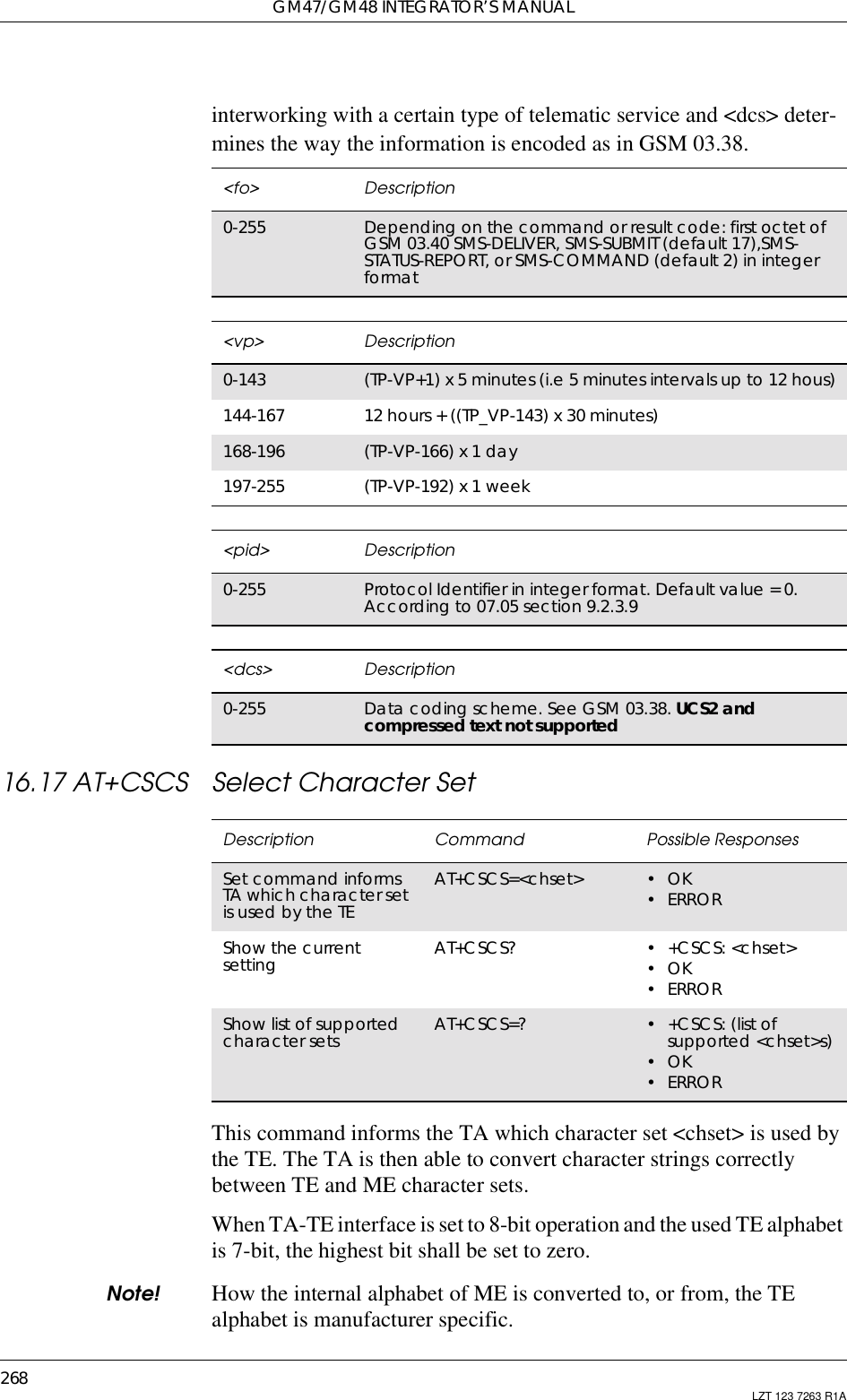
![16. SHORT MESSAGE SERVICES - POINT TO POINT269LZT 123 7263 R1ARead command shows current setting and test command displayconversion schemes implemented in the TA.16.18 AT*ESTL Ericsson SMS Template List EditThis command adds an SMS template, specified by the <text>parameter, to the list of SMS templates at the position specified by the<stix> parameter. If the list already contains an SMS template at theposition <stix> this template is overwritten by the template given by the<text> parameter.If the <text> parameter is omitted, the command removes the SMSTemplate from the list at the position specified by the <stix> parameter.The read command lists all entries in the SMS Template list.<chset > Description“GSM” GSM default alphabet (GSM 03.38 subclause 6.2.1).Default setting“IRA” International reference alphabet (ITU-T T.50 [3]). Note:recommended default setting by GSM 07.07. [2]“8859-n” ISO 8859 Latin n(1-6) character set"UTF8" Universal text format, 8 bits“UCS2” Unicode, 16-bit universal multiple-octet coded characterset (ISO/IEC10646)Description Command Possible ResponsesAdd or delete itemto SMS template list AT*ESTL=<stix>[,<text>] •+CMEERROR•OK•ERRORList all entries in SMStemplate list AT*ESTL? •*ESTL:<stix1>,<text1>[<CR><LF><stix2>,<text2>[…]]+CME ERROR•OK•ERRORShow if thecommand issupportedAT*ESTL=? • *ESTL: (list of supported<stix>s),<ntext>•OK•ERROR<stix> DescriptionInteger value Index to list of SMS templates<text> DescriptionString value SMS template text](https://usermanual.wiki/Sony/6220501-BV.Exhibit-8-Integrators-Manual/User-Guide-247869-Page-269.png)
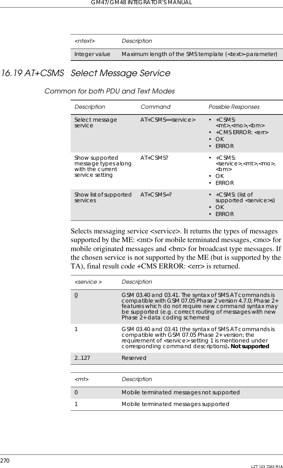
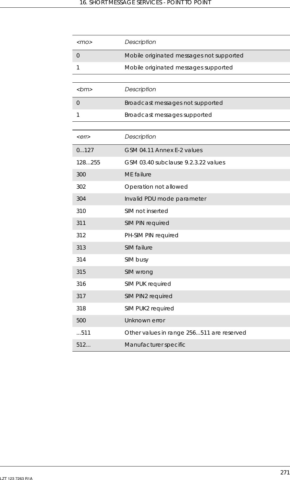

![273LZT 123 7263 R1A17. Short Message Services - Cell Broadcast17.1 AT+CNMI New Message Indications to TESee 16.11, AT+CNMI New Message Indications to TE17.2 AT+CSCB Select Cell Broadcast Message TypeCommon for both PDU and text modesSelects which types of CBMs are to be received by the ME.Description Command Possible ResponsesSelect cell broadcastmessage type AT+CSCB=[<mode>[,<mids>[,<dcss>]]] • +CMS ERROR: <err>•OK•ERRORShows the currentsetting AT+CSCB? •+CSCB:<mode>,<mids>,<dcss>•OK•ERRORShow if the commandis supported AT+CSCB=? •+CSCB:(listofsupported<mode>s)•OK•ERROR<mode> Description0Message types in <mids> and <dcss> are accepted1Message types in <mids> and <dcss> are not accepted.Not supported<mids> Descriptionstring type All different possible combinations of CBM messageidentifiers (refer <mid>) (default is empty string);e.g. “0,1,5-7”<mid> GSM 03.41 CBM Message Identifier in integerformat<dcss> Descriptionstring type All different possible combinations of CBM data codingschemes (refer to <dcs>). Default is empty string);e.g. “0-3,5”. Not supported](https://usermanual.wiki/Sony/6220501-BV.Exhibit-8-Integrators-Manual/User-Guide-247869-Page-273.png)

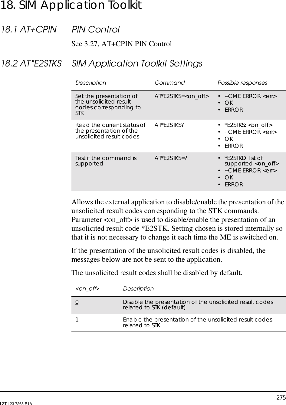
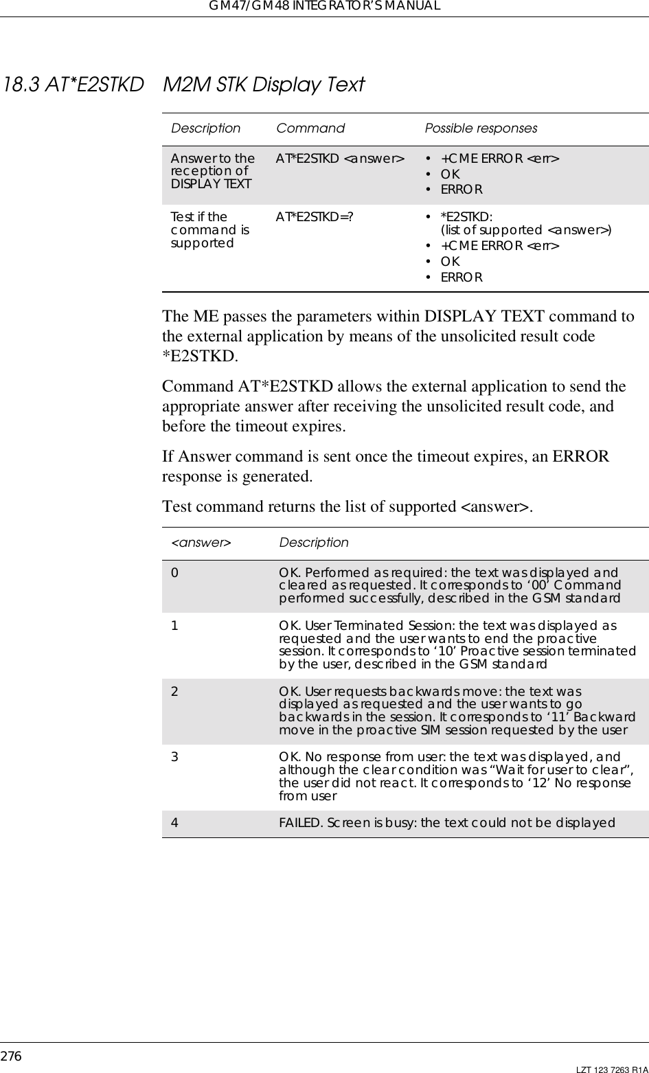
![18. SIM APPLICATION TOOLKIT277LZT 123 7263 R1A18.4 AT*E2STKG M2M STK Get InkeyThe ME passes the parameters within GET INKEY command to theexternal application by means of the unsolicited result code E2STKG.The external application then sends AT*E2STKG with the userresponse.Answer command allows the external application to send theappropriate answer, after receiving the unsolicited result code, andbefore the timeout expires.If Answer command is sent once the timeout expires, an ERRORresponse is generated.If <answer> parameter is 4, a failure has occurred and no moreparameters are sent. If the extra parameters are sent, the ME indicatesERROR.Description Command Possible responsesAnswer to thereception ofGET INKEYAT*E2STKG=<answer>,[<response_type>,<user_response>]• +CME ERROR <err>•OK•ERRORTest if thecommand issupportedAT*E2STKG=? •*E2STKG:(list of supported <answer>),(list of supported<response_type>),(list of supported<user_response>)• +CME ERROR <err>•OK•ERROR<user_response> DescriptionString type Field of 1 to 2 bytes length in string type formatbetween “”. Coding is defined in <response_type>.Length shall be 2 bytes when coding is UCS2 .Otherwise it shall be 1 byte](https://usermanual.wiki/Sony/6220501-BV.Exhibit-8-Integrators-Manual/User-Guide-247869-Page-277.png)
![GM47/GM48 INTEGRATOR’S MANUAL278 LZT 123 7263 R1A18.5 AT*E2STKI M2M STK Get InputThe ME shall pass the parameters within GET INPUT command to theexternal application by means of the unsolicited result code E2STKI.The external application sends AT*E2STKI with the user response.Command AT*E2STKI allows the external application to send theappropriate answer after receiving the unsolicited result code, andbefore the timeout expires.If Answer command is sent once the timeout expires, an ERRORresponse is generated.<answer> Description0OK. Performed as required: the text was displayed. Itcorresponds to ‘00’ Command performed successfully,described in the GSM standard1OK.UserTerminatedSession:thetextwasdisplayedasrequested and the user wants to end the proactivesession. It corresponds to ‘10’ Proactive sessionterminated by the user, described in the GSM standard2OK. User requests backward move: the text wasdisplayed as requested and the user wants to gobackwards in the session. It corresponds to ‘11’Backward move in the proactive SIM sessionrequested by the user3OK. No response from user: the text was displayed, andthe user did not react. It corresponds to ‘12’ Noresponse from user4FAILED. Screen is busy: the text could not be displayed<response_type> Description0Response type shall be digits (0-9, *, # and +)1Response type shall be SMS default alphabet2Response type shall be UCS2 alphabet3Response type shall be “Yes/No” responseDescription Command Possible responsesAnswer to thereception of GETINPUTAT*E2STKI <answer>,[<response_type>,<response_length>,<user_response>]• +CME ERROR <err>•OK• ERRORTest if thecommand issupportedAT*E2STKI=? • *E2STKI: (list of supported<answer>),(list of supported<response_type>),(list of supported<prompt_text_length>• +CME ERROR <err>•OK• ERROR](https://usermanual.wiki/Sony/6220501-BV.Exhibit-8-Integrators-Manual/User-Guide-247869-Page-278.png)
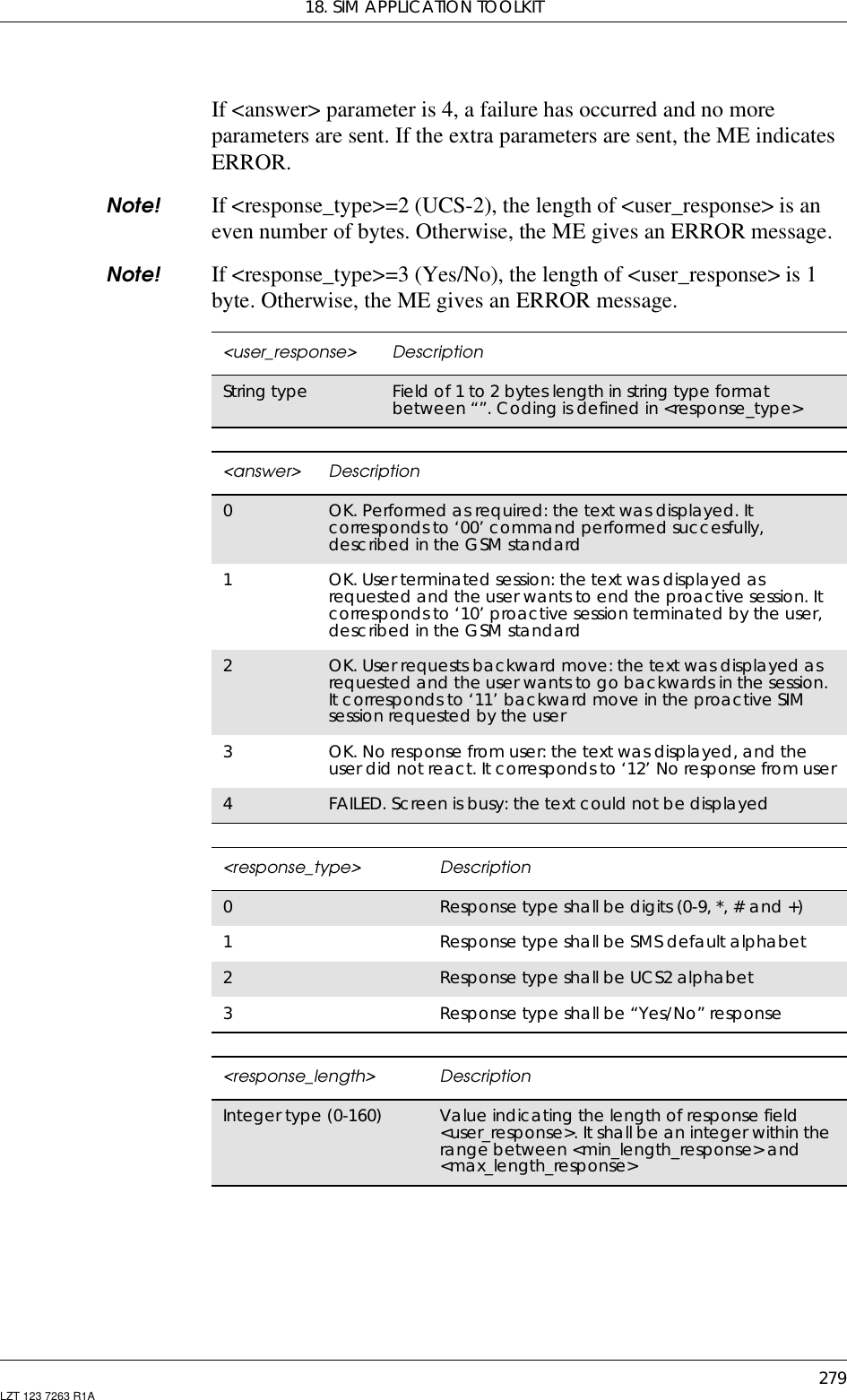
![GM47/GM48 INTEGRATOR’S MANUAL280 LZT 123 7263 R1A18.6 AT*E2STKL M2M STK Select ItemThe ME shall pass the parameters within SELECT ITEM command tothe external application by means of the unsolicited result code*E2STKL.Command AT*E2STKL allows the external application to send theappropriate answer after receiving the unsolicited result code, andbefore the timeout expires.If Answer command is sent once the timeout expires, an ERRORresponse is be generated.<prompt_coding> Description0Text is coded in unpacked format, using the SMSdefault 7-bit coded alphabet, as defined inGSM03.38withbit8setto0. Itcorrespondstodata coding scheme of 8 bit1Text is coded in packed format, using the SMSdefault 7-bit coded alphabet, packed in 8-bitoctets, as defined in GSM 03.38. It correspondsto data coding scheme of 7 bit GSM defaultalphabet2Text is coded in UCS2 alphabet, as defined inGSM 03.38. It corresponds to data codingscheme of 16 bit UCS2 alphabet<prompt_text_length> DescriptionInteger type (0-210) Value indicating the maximum length of field<prompt_text><prompt_text> DescriptionString type Field of maximum length <prompt_text_length>,in string type between “”. Coding is defined in<prompt_coding>Description Command Possible responsesAnswer to thereception ofSELECT ITEMAT*E2STKL=<answer>,[<user_response>] • +CME ERROR <err>•OK•ERRORTest if thecommand issupportedAT*E2STKL=? • *E2STKL: (list of supported<answer>),(list of supported<user_response>)• +CME ERROR <err>•OK•ERROR](https://usermanual.wiki/Sony/6220501-BV.Exhibit-8-Integrators-Manual/User-Guide-247869-Page-280.png)
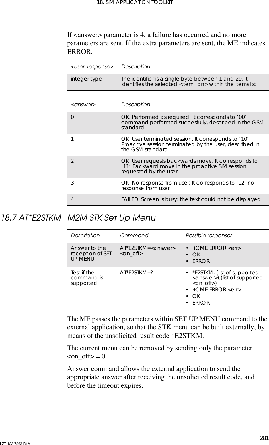
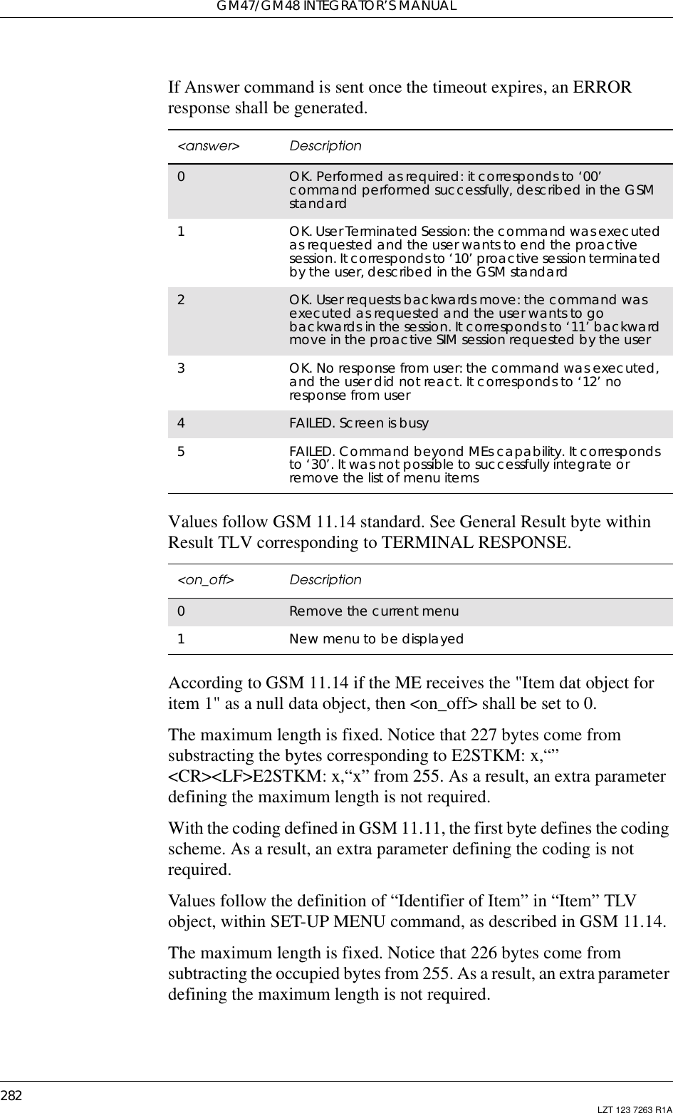
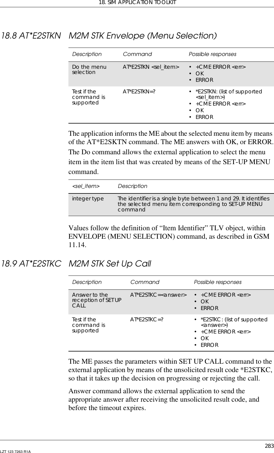
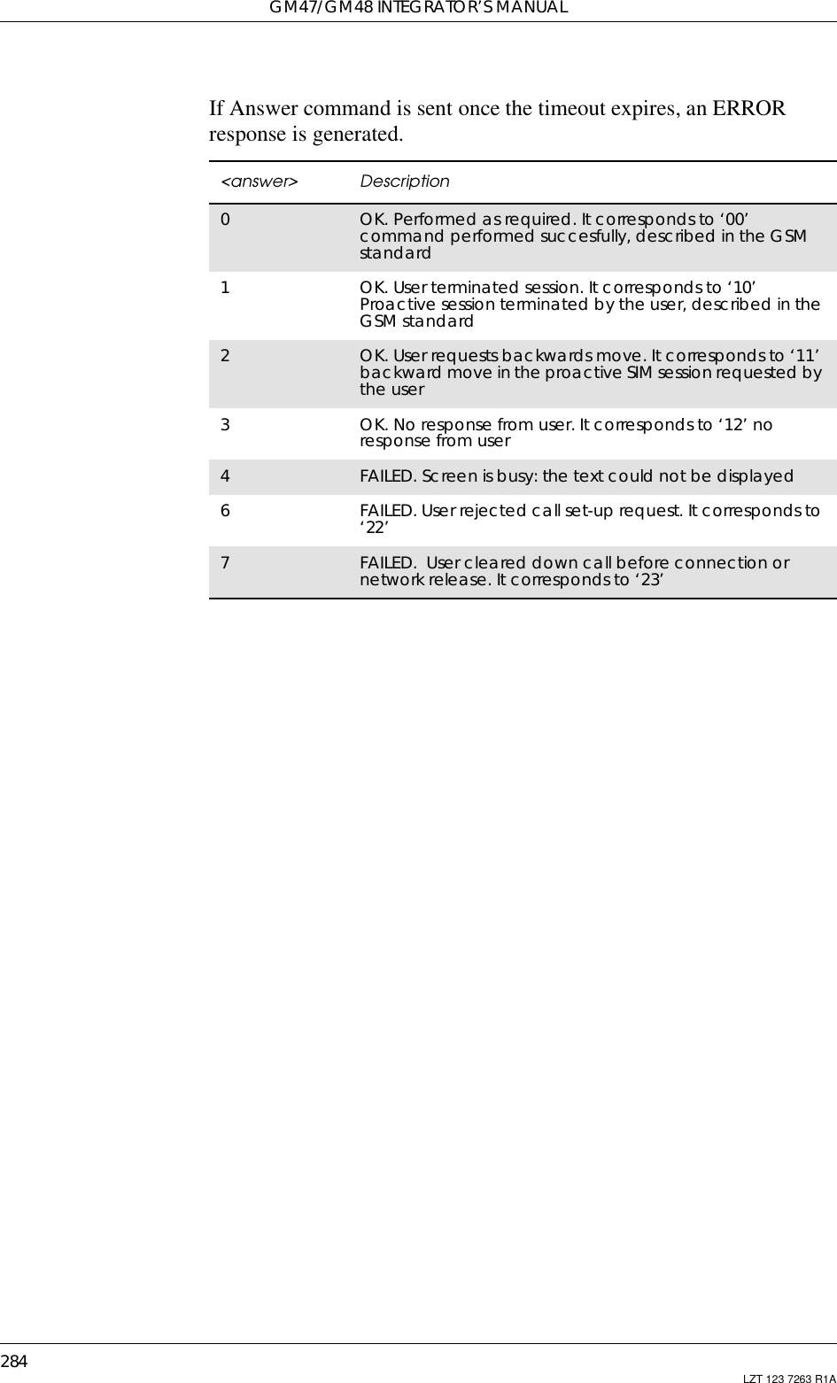
![285LZT 123 7263 R1A19. Supplementary Services19.1 AT+CPIN PIN ControlSee 3.27, AT+CPIN PIN Control19.2 AT+CACM Accumulated Call MeterResets the Advice of Charge related accumulated call meter value inSIM file EFACM. ACM contains the total number of home units forboth the current and preceding calls. SIM PIN2 is usually required toreset the value. If setting fails in an ME error, +CME ERROR: <err> isreturned. Refer subclause 9.2 for <err> values.Note! This command must take into account what line is chosen withAT*ELIN or via the MMIRead command returns the current value of ACM.Description Command Possible ResponsesReset the ACM(Accumulated CallMeter) value on theSIMAT+CACM=[<passwd>] •+CMEERROR:<err>•OK•ERRORShow the current value AT+CACM? •+CACM:<acm>+CME ERROR: <err>•OK•ERRORTests if the command issupported AT+CACM=? •+CMEERROR:<err>•OK•ERROR<passwd> DescriptionString type SIM-PIN2<acm> DescriptionString type Accumulated call meter value similarly coded as <ccm>under +CAOC](https://usermanual.wiki/Sony/6220501-BV.Exhibit-8-Integrators-Manual/User-Guide-247869-Page-285.png)
![GM47/GM48 INTEGRATOR’S MANUAL286 LZT 123 7263 R1A19.3 AT+CAMM Accumulated Call Meter MaximumSets the Advice of Charge related accumulated call meter maximumvalue in SIM file EFACMmax. ACMmax contains the maximumnumber of home units allowed to be consumed by the subscriber. WhenACM (refer +CACM) reaches ACMmax calls are prohibited (see alsoGSM 02.24 [26]). SIM PIN2 is usually required to set the value. Ifsetting fails in an ME error, +CME ERROR: <err> is returned.Read command returns the current value of ACMmax.Description Command Possible ResponsesSet command sets theAdvice of Chargerelated accumulatedcall meter maximumvalue in SIM fileEFACMmaxAT+CAMM=[<acmmax>[,<passwd>]] •+CMEERROR:<err>•OK•ERRORRead the current value AT+CAMM? •+CAMM:<acmmax>+CME ERROR: <err>•OK•ERRORTest if the command ifsupported AT+CAMM=? •+CMEERROR:<err>•OK•ERROR<acmmax> DescriptionString type Accumulated call meter maximum value similarly codedas <ccm> under +CAOC; value zero disables ACMmaxfeature<passwd> DescriptionString type SIM PIN2](https://usermanual.wiki/Sony/6220501-BV.Exhibit-8-Integrators-Manual/User-Guide-247869-Page-286.png)
![19. SUPPLEMENTARY SERVICES287LZT 123 7263 R1A19.4 AT+CAOC Advice of ChargeUse of Advice of Charge supplementary service command (GSM 02.24[11] and GSM 02.86 [12]) enables the subscriber to get informationabout the cost of calls. With <mode>=0, the execute command returnsthe current call meter value from the ME. The command also includesthe possibility to enable an unsolicited event reporting of the CCMinformation. The unsolicited result code +CCCM: <ccm> is sent whenthe CCM value changes, but no more than every 10 seconds.Deactivation of the unsolicited event reporting is made with the samecommand.Read command indicates whether the unsolicited reporting is activatedor not. Read command is available when the unsolicited result code issupported.It is recommended (although optional) that the test command return thesupported mode values.Description Command Possible ResponsesExecute command AT+CAOC[=<mode>] • [+CAOC: <ccm>]+CME ERROR: <err>•OK•ERRORRead command,shows the currentmodeAT+CAOC? •+CAOC:<mode>•OK•ERRORTest command, showsif the command issupportedAT+CAOC=? •[+CAOC:(listofsupported<mode>s]•OK•ERROR<mode> Description0Query CCM value1Deactivate the unsolicited reporting of CCM value2Activate the unsolicited reporting of CCM value<ccm> DescriptionString type Threebytesofthecurrentcallmetervalueinhexadecimalformat (e.g. “00001E” indicates decimal value 30); value isin home units and bytes are similarly coded as ACMmaxvalue in the SIM](https://usermanual.wiki/Sony/6220501-BV.Exhibit-8-Integrators-Manual/User-Guide-247869-Page-287.png)
![GM47/GM48 INTEGRATOR’S MANUAL288 LZT 123 7263 R1A19.5 AT+CPUC Price Per Unit and Currency TableSets the parameters of Advice of Charge related price per unit andcurrency table in SIM file EFPUCT. PUCT information can be used toconvert the home units (as used in +CAOC, +CACM and +CAMM)into currency units. SIM PIN1 or SIM PIN2 (depending on which SIMcard that is used) is required to set the parameters. If setting fails in anME error, +CME ERROR: <err> is returned.Read command returns the current parameters of PUCT.For information on the character set see AT+CSCS in the ShortMessage Services section.Description Command Possible ResponsesSet command sets theparameters of Adviceof Charge relatedprice per unit andcurrency table in SIMfile EFPUCTAT+CPUC=<currency>,<ppu>[,<passwd>] •+CMEERROR:<err>•OK•ERRORShows the currentvalues AT+CPUC? •+CPUC:<currency>,<ppu>+CME ERROR: <err>•OK•ERRORShows if the commandis supported AT+CPUC=? •OK•ERROR<currency> DescriptionString Alpha-identifier of the currency code (3 characters, e.g.SEK)<ppu> DescriptionString type price per unit; dot is used as a decimal separator (e.g.“2.66”)<passwd> DescriptionString type SIM PIN1 or SIM PIN2](https://usermanual.wiki/Sony/6220501-BV.Exhibit-8-Integrators-Manual/User-Guide-247869-Page-288.png)
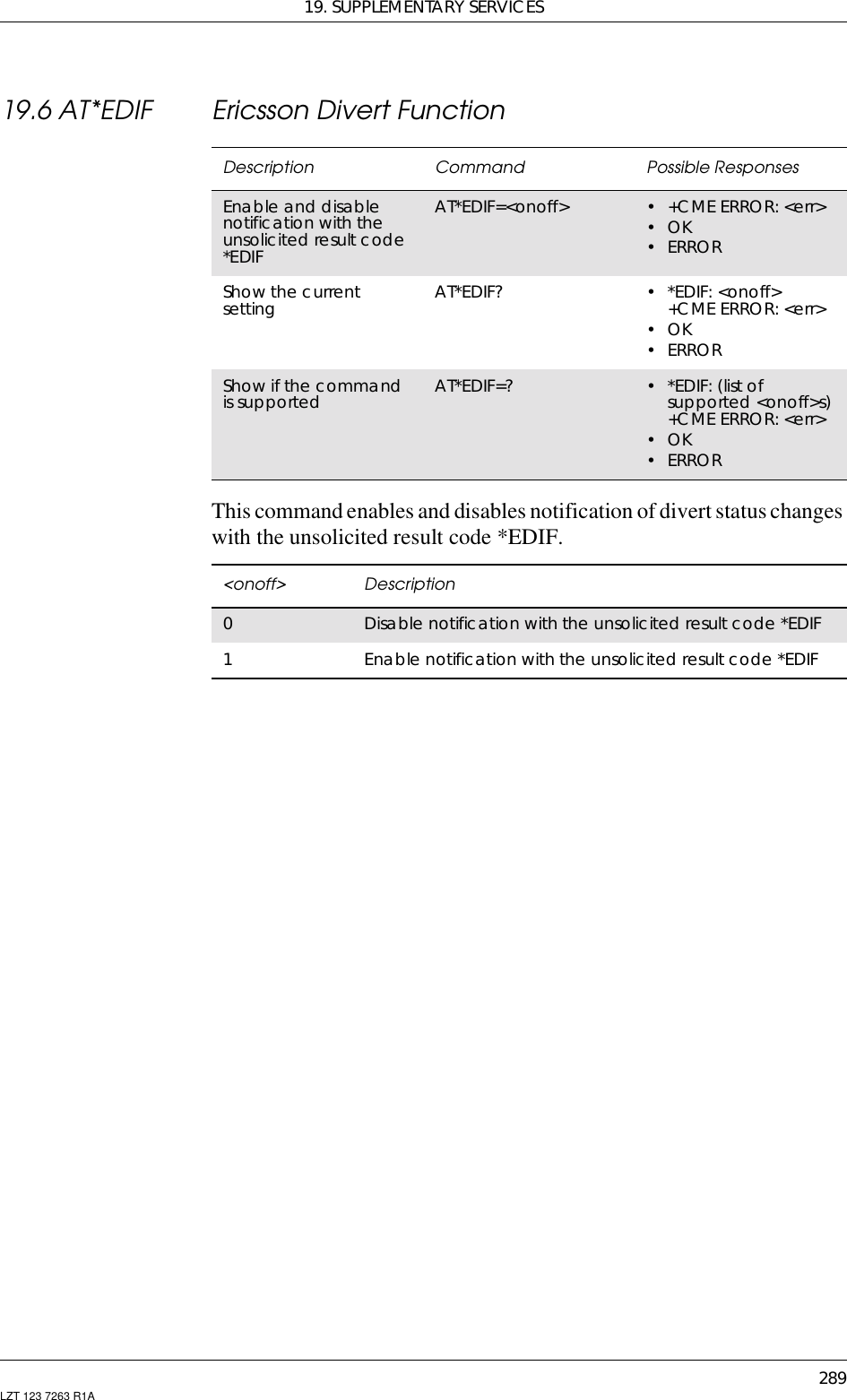
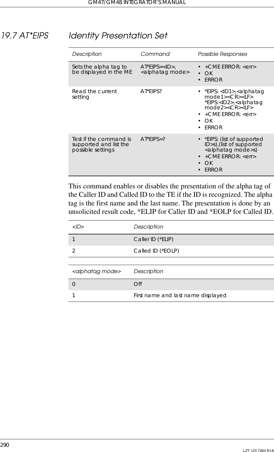
![19. SUPPLEMENTARY SERVICES291LZT 123 7263 R1A19.8 AT*ELIN Ericsson Line SetThis command requests the ME to set the current line to <line>.Note! The following command reads its value from the current line and is thusaffected by the use of *ELIN:AT+CACM - Accumulated Call Meter19.9 AT+CCFC Call Forwarding number and ConditionsThis command allows control of the call forwarding supplementaryservice according to 3GPP TS 22.082 [4]. Registration, erasure,activation, deactivation, and status query are supported. When queryingDescription Command Possible ResponsesSet the current line to<line> AT*ELIN=<line> •+CMEERROR:<err>•OK•ERRORRead the current line AT*ELIN? •*ELIN:<line>+CME ERROR: <err>•OK•ERRORTest if the command issupported AT*ELIN=? •*ELIN:listofsupported <line>s+CME ERROR: <err>•OK•ERROR<line> Description1L12L2Description Syntax Possible ResponsesRequestCallingforwardingnumber andconditionsAT+CCFC=<reason>,<mode>[,<number>[,<type>[,<class>[,<subaddr>[,<satype>[,<time>]]]]]]• +CME ERROR <err>•when <mode>=2 andcommand successful:+CCFC:<status>,<class1>[,<number>,<type>[,<subaddr>,<satype>[,<time>]]][<CR><LF>+CCFC:<status>,<class2>[,<number>,<type>[,<subaddr>,<satype>[,<time>]]][...]]•OK•ERRORShow if thecommand issupportedAT+CCFC=? • + CCFC: (list of supported<reason>s)• +CME ERROR <err>•OK•ERROR](https://usermanual.wiki/Sony/6220501-BV.Exhibit-8-Integrators-Manual/User-Guide-247869-Page-291.png)
![GM47/GM48 INTEGRATOR’S MANUAL292 LZT 123 7263 R1Athe status of a network service (<mode>=2) the response line for ‘notactive’ case (<status>=0) should be returned only if service is not activefor any <class>.<reason> Description0Unconditional1Mobile busy2No reply3Not reachable4All call forwarding (refer 3GPP TS 22.030 [19])5All conditional call forwarding (refer 3GPP TS 22.030 [19])<mode> Description0Disable1Enable2Query status3Registration4Erasure<number> Descriptionstring type String type phone number of forwarding address in formatspecified by <type><type> Descriptioninteger format Type of address octet(refer GSM 04.08 [3] section 10.5.4.7)129 ISDN/telephony numbering plan, national/internationalunknown. Default setting if ‘+’ is not in <sca>145 ISDN/telephony numbering plan, international number.Default setting if '+' is in <sca>161 ISDN/telephony numbering plan, national number128 - 255 Other values refer GSM 04.08 [3] section 10.5.4.7<subaddr> Descriptionstring type string type subaddress of format specified by <satype>.Not supported](https://usermanual.wiki/Sony/6220501-BV.Exhibit-8-Integrators-Manual/User-Guide-247869-Page-292.png)
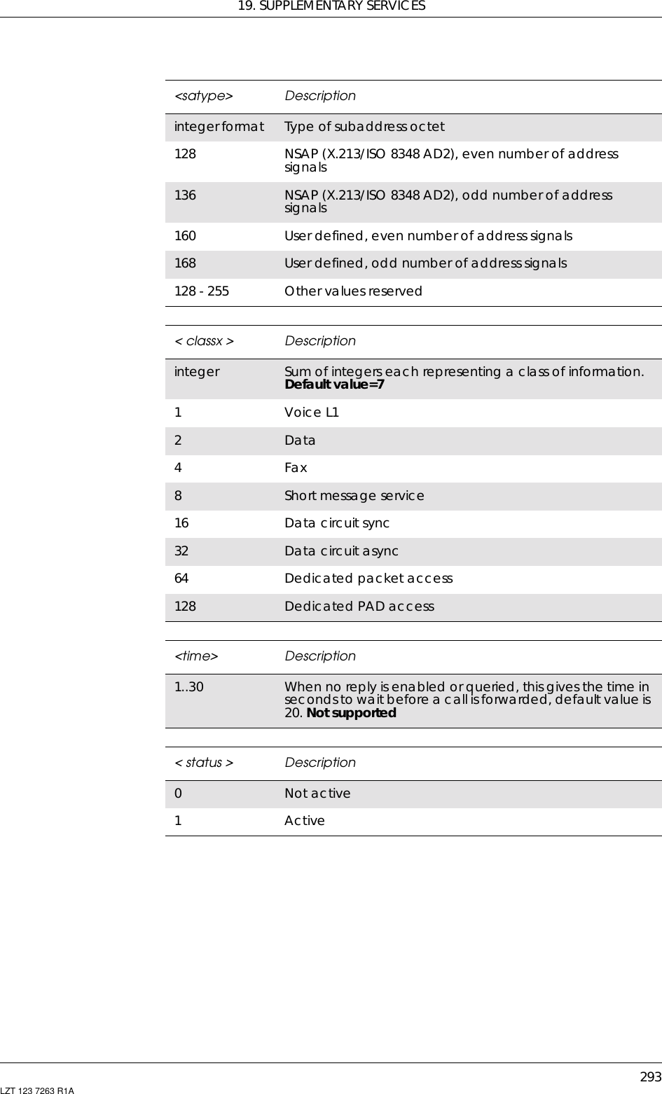
![GM47/GM48 INTEGRATOR’S MANUAL294 LZT 123 7263 R1A19.10 AT+CCWA Call WaitingThis command allows control of the call waiting supplementary serviceaccording to 3GPP TS 22.083 [5]. Activation, deactivation and statusquery are supported. When querying the status of a network service(<mode> = 2) the response line for 'not active' case (<status> = 0)should be returned only if service is not active for any <class>.Parameter <n> is used to disable/enable the presentation of anunsolicited result code +CCWA:<number>,<type>,<class>,[<alpha>][,<CLI validity>] to the TE whencall waiting service is enabled. The command is abortable when thenetwork is interrogated.The interaction of this command with other commands based on otherGSM/UMTS supplementary services is described in the GSM/UMTSstandards.Test command returns values supported by the TA as a compoundvalue.Description Command Possible ResponsesRequest callwaiting AT+CCWA=[<n>[,<mode>[,<class>]]]•when<mode>=2 and commandsuccessful:+CCWA:<status>,<class1>[<CR><LF>+CCWA: <status>,<class2>[…]]+CME ERROR <err>•OK•ERRORShow thecurrent setting AT+CCWA? • +CCWA: <n>+CME ERROR <err>•OK•ERRORShow if thecommand issupportedAT+CCWA=? • +CCWA: (list of supported <n>s)+CME ERROR <err>•OK•ERROR<n> Description0Disable1Enable<mode> Description0Disable1Enable2Query status](https://usermanual.wiki/Sony/6220501-BV.Exhibit-8-Integrators-Manual/User-Guide-247869-Page-294.png)
![19. SUPPLEMENTARY SERVICES295LZT 123 7263 R1A<classx> Descriptioninteger Sum of integers each representing a class of information.Default value=71Voice L12Data4Fax8Short message service16 Data circuit sync32 Data circuit async64 Dedicated packet access128 Dedicated PAD access<status > Description0Not active1Active<number > DescriptionString type String type phone number of forwarding address in formatspecified by <type><type > DescriptionInteger format Type of address octet in integer format (GSM 04.0810.5.4.7, [3]);<err> Description0Phone failure3Operation not allowed4Operation not supported21 Invalid index30 No network service31 Network timeout100 Unknown](https://usermanual.wiki/Sony/6220501-BV.Exhibit-8-Integrators-Manual/User-Guide-247869-Page-295.png)
![GM47/GM48 INTEGRATOR’S MANUAL296 LZT 123 7263 R1A19.11 AT+CHLD Call Hold and MultipartyThis command allows control of the following call related services:• a call can be temporarily disconnected from the ME but theconnection is retained by the network;• multiparty conversation (conference calls);• the served subscriber who has two calls (one held and the othereither active or alerting) can connect the other parties and release theserved subscriber's own connection.Calls can be put on hold, recovered, released, added to conversation,and transferred similarly as defined in 3GPP TS 22.030.This is based on the GSM/UMTS supplementary services HOLD (CallHold; refer 3GPP TS 22.083 [5] clause 2), MPTY (MultiParty; refer3GPP TS 22.084 [22]) and ECT (Explicit Call Transfer; refer 3GPP TS22.091 [29]). The interaction of this command with other commandsbased on other GSM/UMTS supplementary services is described in theGSM/UMTS standards.Note! Call Hold and MultiParty are only applicable to teleservice 11.It is recommended (although optional) that test command returns a listof operations which are supported. The call number required by someoperations is denoted by “x” (e.g. +CHLD: (0,0x,1,1x,2,2x,3)).Description Command Possible ResponsesRequest call relatedsupplementaryservicesAT+CHLD=<n> • +CME ERROR <err>•OK•ERRORShow if the commandis supported AT+CHLD=? •+CHLD:(listofsupported <n>s)• +CME ERROR <err>•OK•ERROR<n> Description... Integer type; equals to numbers entered before SENDbutton in GSM 02.30 [7] subclause 4.5.5.10Releases all held calls or sets User Determined User Busy(UDUB) for a waiting call0X ReleasesaspecificcallXfromaheldmultipartycall1Releases all active calls (if any exist) and accepts theother (held or waiting) call1X Releases a specific active call X](https://usermanual.wiki/Sony/6220501-BV.Exhibit-8-Integrators-Manual/User-Guide-247869-Page-296.png)
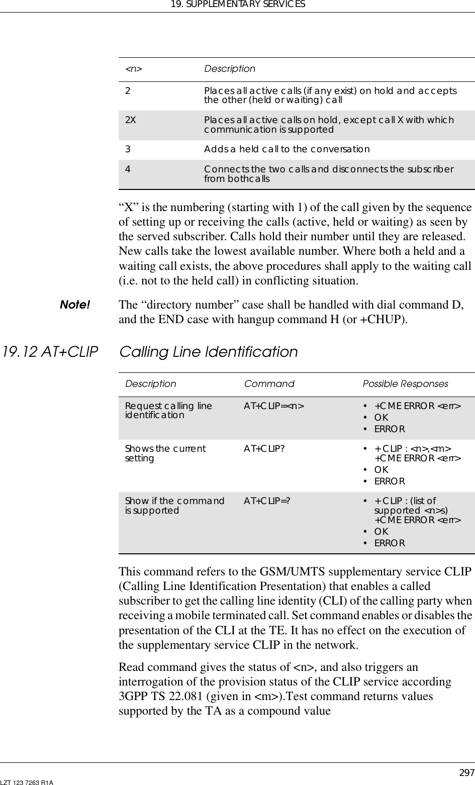
![GM47/GM48 INTEGRATOR’S MANUAL298 LZT 123 7263 R1ATest command returns values supported by the TA as a compoundvalue.Note! When CLI is not available ( <CLI validity>=2), <number> shall be anempty string (“”) and <type> value willnot be significant. Nevertheless,TA may return the recommended value 128 for <type> ((TON/NPIunknown in accordance with GSM 04.08 [8] subclause 10.5.4.7). WhenCLI has been withheld by the originator, (<CLI validity>=1) and theCLIP is provisioned with the "override category" option (refer 3GPP TS22.081[3] and 3GPP TS 23.081[40]), <number> and <type> isprovided. Otherwise, TA shall return the same setting for <number>and <type> as if the CLI was not available.<n> Description0Disable1Enable<m> Description0CLIP not provisioned1CLIP provisioned2Unknown (e.g. no network)<err> Description0Phone failure3Operation not allowed4Operation not supported21 Invalid index30 No network service31 Network timeout100 Unknown](https://usermanual.wiki/Sony/6220501-BV.Exhibit-8-Integrators-Manual/User-Guide-247869-Page-298.png)
![19. SUPPLEMENTARY SERVICES299LZT 123 7263 R1A19.13 AT+CLIR Calling Line Identification RestrictionThis command refers to CLIR-service according to GSM 02.81 [6] thatallows a calling subscriber to enable or disable the presentation of theCLI to the called party when originating a call.Set command overrides the CLIR subscription (default is restricted orallowed) when temporary mode is provisioned as a default adjustmentfor all following outgoing calls. Using the opposite command canrevoke this adjustment. If this command is used by a subscriber withoutprovision of CLIR in permanent mode the network will act accordingGSM 02.81 [6].The setting shall be per logical channel.When the MS is turned off and then turned on again the parametersetting <n> shall turn back to default, i.e. the presentation of CLI shallbe used according to the subscription of the CLIR service, <n> is 0.Read command gives the default adjustment for all outgoing calls(given in <n>), and also triggers an interrogation of the provision statusof the CLIR service (given in <m>).Test command returns values supported by the TA as a compoundvalue.Note! On a per call base CLIR functionality is explained in subclause “ITU-TV.25ter [13] dial command”.Description Command Possible ResponsesRequest calling lineidentification restriction AT+CLIR=[<n>] • +CME ERROR <err>•OK•ERRORRead the currentsetting AT+CLIR? •+CLIR:<n>,<m>• +CME ERROR <err>•OK•ERRORTest if the command issupported AT+CLIR=? •+CLIR:(listofsupported <n>s)• +CME ERROR <err>•OK•ERROR<n> Description0Presentation indicator is used according to thesubscription of the CLIR service1CLIR invocation2CLIR suppression](https://usermanual.wiki/Sony/6220501-BV.Exhibit-8-Integrators-Manual/User-Guide-247869-Page-299.png)
![GM47/GM48 INTEGRATOR’S MANUAL300 LZT 123 7263 R1A19.14 AT+CSSN Supplementary Service NotificationThis command refers to supplementary service related network initiatednotifications. The set command enables/disables the presentation ofnotification result codes from TA to TE.When <n>=1 and a supplementary service notification is received aftera mobile originated call setup, unsolicited result code +CSSI:<code1>[,<index>] is sent to TE before any other MO call setup resultcodes presented in this ETS or in V.25ter [13]. When several different<code1>s are received from the network, each of them shall have itsown +CSSI result code.When <m>=1 and a supplementary service notification is receivedduring a mobile terminated call setup or during a call, or when a forwardcheck supplementary service notification is received, unsolicited resultcode +CSSU: <code2>[,<index>] is sent to TE. In case of MT callsetup, result code is sent after every +CLIP result code (refer command"Calling line identification presentation +CLIP") and when severaldifferent <code2>s are received from the network, each of them shallhave its own +CSSU result code.Note! The difference between <index> and <cindex> is that <index> is aposition mark while <cindex> is a unique value for each CUG. <index>is not supported.<m> Description0CLIR not provisioned1CLIR provisioned in permanent mode2Unknown (e.g. no network)3CLIR temporary mode presentation restricted4CLIR temporary mode presentation allowedDescription Command Possible ResponsesPresentation ofnotification resultcodes from TA to TEAT+CSSN=[<n>[,<m>]] • +CME ERROR <err>•OK•ERRORRead the currentsetting AT+CSSN? •+CSSN:<n>,<m>• +CME ERROR <err>•OK•ERRORTest if the command issupported AT+CSSN=? •+CSSN:(listofsupported <n>s),(listof supported <m>s)• +CME ERROR <err>•OK•ERROR](https://usermanual.wiki/Sony/6220501-BV.Exhibit-8-Integrators-Manual/User-Guide-247869-Page-300.png)
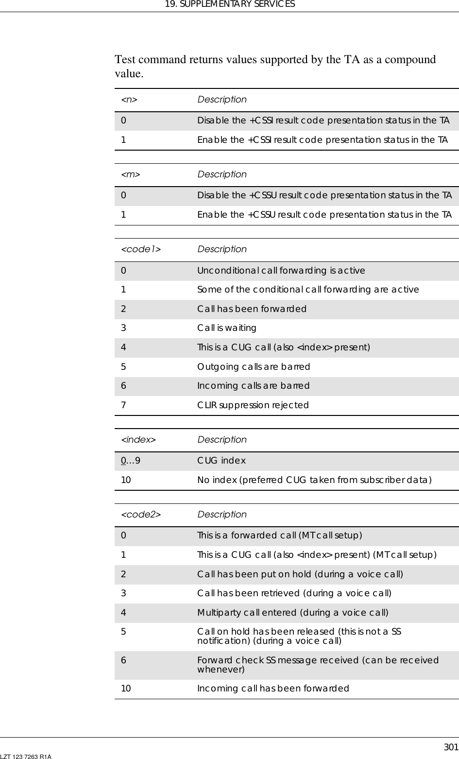
![GM47/GM48 INTEGRATOR’S MANUAL302 LZT 123 7263 R1A19.15 AT+CUSD Unstructured Supplementary Service DataThis command allows control of the Unstructured SupplementaryService Data (USSD) according to GSM 02.90. Both network andmobile initiated operations are supported. Parameter <n> is used todisable/enable the presentation of an unsolicited result code (USSDresponse from the network, or network initiated operation) +CUSD:<m>[,<str>,<dcs>] to the TE. In addition, value <n>=2 is used to cancelan ongoing USSD session. If <n> is not given then the default value 0is taken.When <str> is given, a mobile initiated USSD string or a responseUSSD string to a network initiated operation is sent to the network. Theresponse USSD string from the network is returned in a subsequentunsolicited +CUSD: result code.The interaction of this command with other commands based on otherGSM supplementary services is described in the GSM standard.Test command returns values supported by the TA as a compoundvalue.Some different scenarios are shown below:• An incoming network initiated USSD-Notify should be presented tothe external application as an unsolicited result code +CUSD: if theexternal application has enabled result code presentation.• An incoming USSD-request asking for a reply should sent to theexternal application as an unsolicited result code +CUSD: if theexternal application has enabled result code.• If the external application answers to the request with the commandAT+CUSD then the ME sends the answer to the network.• A USSD-request sent with the command AT+CUSD from theexternal application.Description Command Possible ResponsesRequest unstructuredsupplementary servicedataAT+CUSD=[<n>[,<str>]] •+CMEERROR:<err>•OKShow supportedmessage types alongwith the current servicesettingAT+CUSD? •+CUSD:<n>•OK•ERRORShow list of supportedservices AT+CUSD=? •+CUSD:(listofsupported <n>s)•OK•ERROR](https://usermanual.wiki/Sony/6220501-BV.Exhibit-8-Integrators-Manual/User-Guide-247869-Page-302.png)