Spectrum Technologies SP911 Access Point User Manual users manual
Spectrum Technologies Corporation Access Point users manual
UserManual.wiki
>
Spectrum Technologies
>
SP911 User Manual
users manual
Navigation menu
Upload a User Manual
Namespaces
Wiki Guide
HTML
PDF
Info
Views
User Manual
Discussion / Help
Navigation

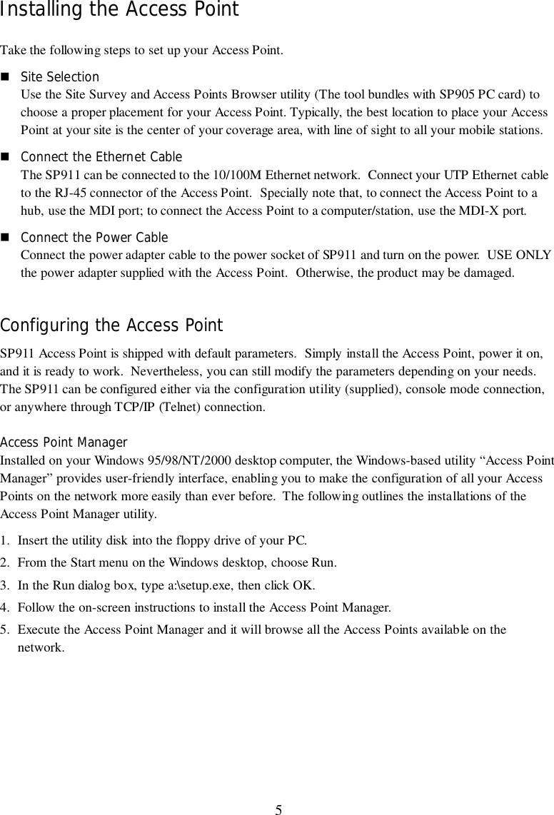
![7console, then you will be able to make the configuration via the TCP/IP connection.Note: the default password to get access to the Access Point is “default”.The following are the commands provided for configuring the Access Point. In loader mode, i.e., novalid firmware in the Access Point, only the commands with an asterisk (*) are provided.Note: [xxx] stands for optional arguments.info*Display some basic information of the Access Point, for example, firmware version, frequencydomain, etc.passwdChange the password of the Access Point.ping ip_addr [num_pings] [data_size]Ping (ICMP echo) to an ip_addr host with optional num_pings times with optional data size in alength of data_size.saveSave your new configuration.auth mode | add | del | list| clear | save|The 'auth' command contains sub-commands that allow you to manage the access control (MACaddress filter) of the Access Point. The access control table consists of a list for you to control theaccess of any stations or repeaters. The sub-commands are listed below:mode open | allow: set the access control mode. The definition of each mode is indicated asfollows:• open: open to public (default)• allow: only allow access of the authorized stations/repeaters.add mac_addr:add an address into the access control tabledel mac_addr |index:remove an address, or index an address from the access control tablesetList the configuration information.set defaultRestore the default setting of the Access Point except for IP addresses. Take a note that a 'save'command is required for changes to take effect.set apname | channel | essid | rts_threshold | frag_threshold | ip_address | ip_netmask | ip_gatewayTo change settings, type “set xxx (parameter) xxxx (value). For example, set channel 7 commandwill set the channel to number 7; set essid “Your Network” command will set the ESSID as YourNetwork. Remember that, a 'save' command is required for changes to take effect.](https://usermanual.wiki/Spectrum-Technologies/SP911/User-Guide-131830-Page-7.png)
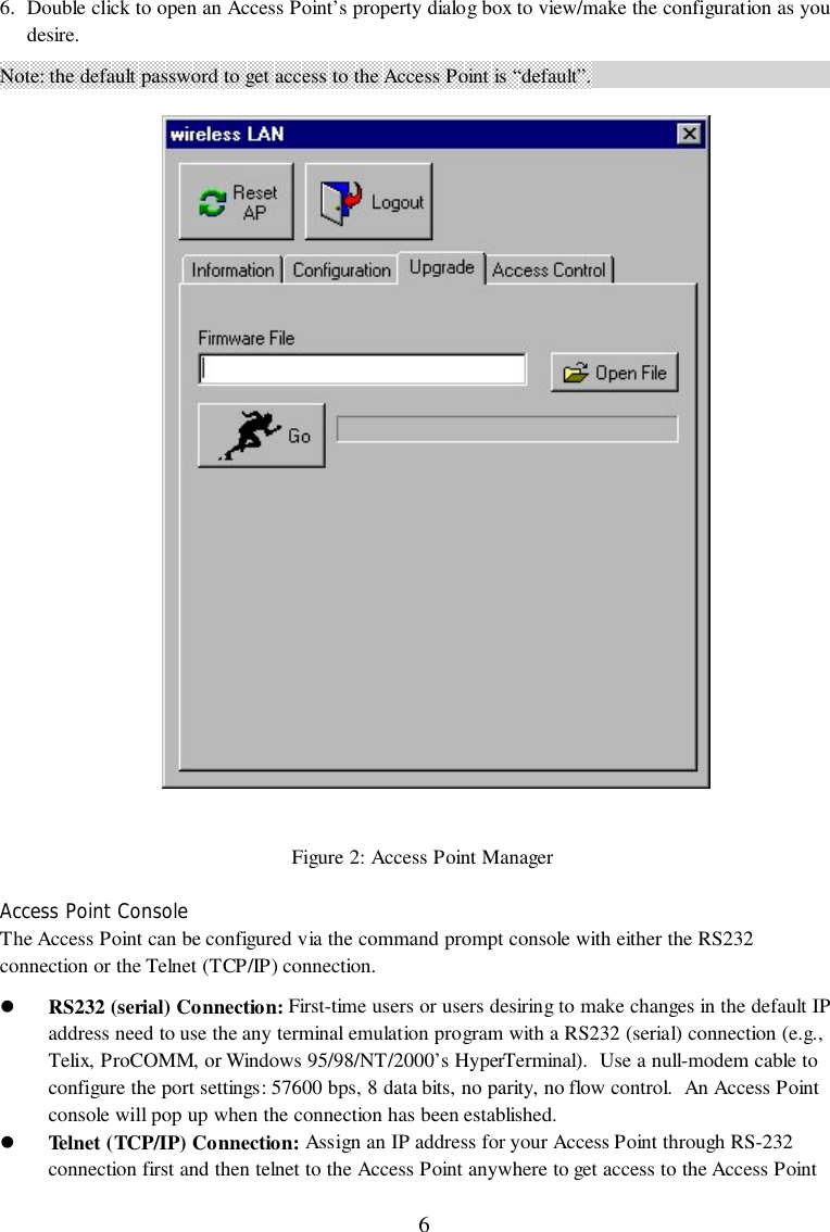
![8Parameter Description Default Valueapname A textual name for the identification of SP911. apXXXXXX(where XXXXXX isthe last six octets ofSP911's MAC add.)channel The radio channel number. 1essid The ESS ID (a.k.a., SSID) of the Access Point. My Networkrts_threshold The threshold (bytes) for enabling RTS/CTS handshake.Data with its frame size larger than this value will performthe RTS/CTS handshake. Range of value: 0~2432.2432frag_threshold The threshold (bytes) for the fragmentation boundary. Datawill be transmitted in fragments which its size does notexceed this value. Range of value: 256~2432.2432ip_address The IP address of SP911. 192.168.1.1ip_netmask The subnet mask address of SP911. 255.255.255.0ip_gateway The default gateway address of SP911. 192.168.1.254Table 2: Parameter of Set commandlist [start/end]:display the content of the access control mode and the address list. The optional arguments, startand end, can be affixed to select the range of items to be listed.clear:clear all the addresses in the access control table.cls*Clear the console screen.exit*Exit the console.help*Print a help screen.rz*Receive a firmware file by the Zmodem protocol. The console will enter Zmodem receiving modeand then use the "file upload" function of your terminal emulation program to upload a newfirmware file (ap.img) to the Access Point. Upon completion, always remember to type the 'reset'command for running the Access Point with the new firmware.reset*Issue a reset signal. The Access Point will be reset if user confirms.](https://usermanual.wiki/Spectrum-Technologies/SP911/User-Guide-131830-Page-8.png)