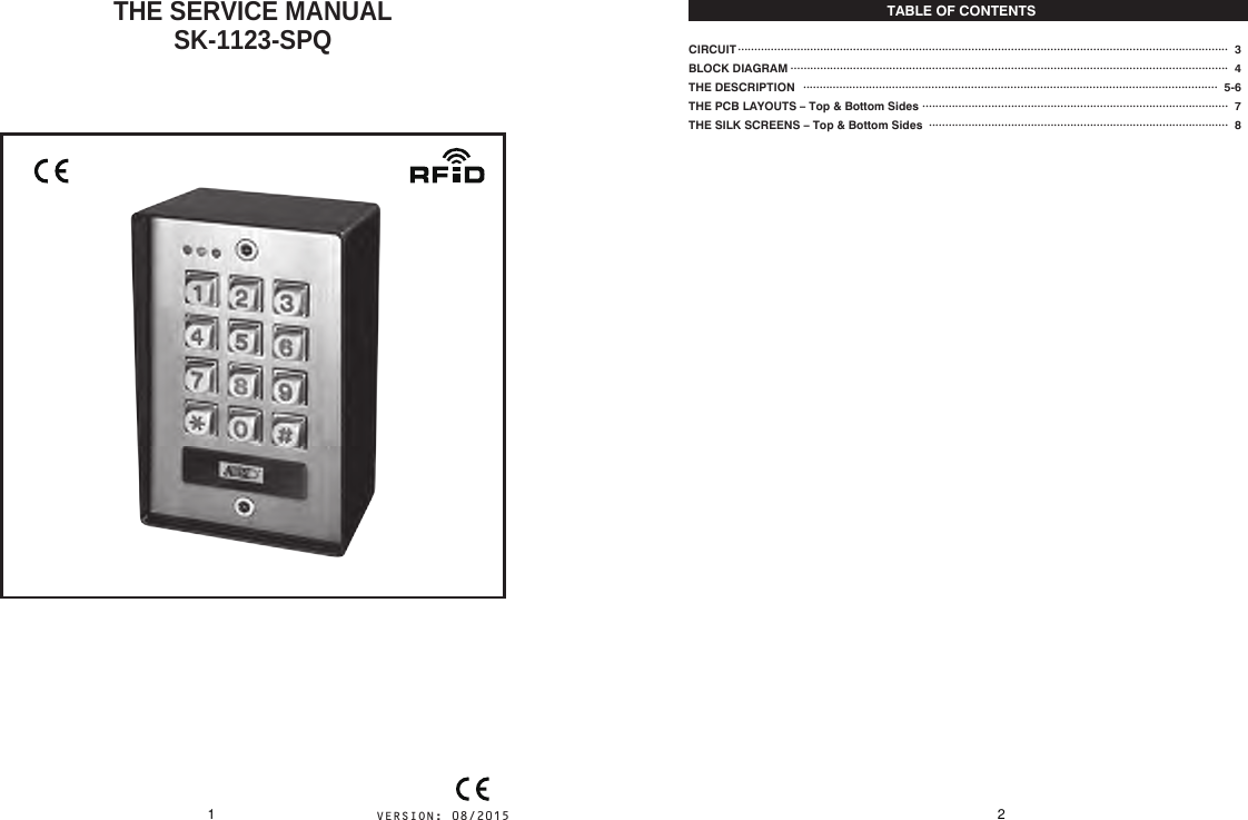
Superior Electronics 1123SPQ Access Control Keypad with Proximity Card Reader User Manual THE SERVICE MANUAL SK 1123 SPQ

Superior Electronics Corporation Access Control Keypad with Proximity Card Reader THE SERVICE MANUAL SK 1123 SPQ

User Manual

  THE SERVICE MANUALSK-1123-SPQTABLE OF CONTENTSCIRCUIT BLOCK DIAGRAMTHE DESCRIPTIONTHE PCB LAYOUTS – Top & Bottom SidesTHE SILK SCREENS – Top & Bottom Sides·····················································································································································  3·····································································································································  4······························································································································  5-6    ·····························································································  7···························································································  81 2
POWER SUPPLYSWITCHING POWER SUPPLYThe XL1509 is a 150 KHz fixed frequency PWM buck (step-down) DC/DC converter, capable of driving a 2A load with high efficiency, low ripple and excellent line and load regulation.Referring to schematic diagram figure 1, input voltage range from DC12V to DC24V step down to DC9V , then output to RELAY unit and 78M05 regulator.5V VOLTAGE REGULATOR78M05 provide a stable voltage (DC5V) to MCU unit.BACK-LIT JUMPERConnecon TerminalsTerminals No.Common ground outputKeypad  Acve  Output  -  NPN  Transistor  ground  output  ,  max. 100mA@24VDCDuress  Output  –  NPN  Transistor  ground  output,  max. 100mA@24VDC. Triggers a silent alarm or other device when the user enters a duress code.Door  Sensor  –  Connect  to  an  oponal  N.C.  sensor  such  as  a magnec  contact  to  monitor  if  the  door  Output  1  is  open  or closed. Connect to ground if not used.Output  1  Inhibit  –  N.O. input, connected  to  Interlock  control of second keypad if needed so that if one keypad is used to open a door Output 1 , the other is temporarily disabled.Interlock  control  –  N.O.  input  ,  connect  to  Output  1  Inhibit  of second keypad if needed so that if one  keypad is used to open door Output 1, the other is temporarily disabled.Tamper switch output – N.C. contact , max. 50mA@24VDC. Connect to the N.C. 24-hour protecon zone of an alarm if needed.Egress In - N.O. Push  buon contact to ground, Press buon to Iniate door unlock Output 1T9T10T11T13T15T16Terminal NameEG INKEY ACTDU OUTT12 GNDDOOR SENST14 O/P 1 INHIB.INT. LOCKTamperT17 TamperDescriponConnecon TerminalsTerminals No.T1 Connect to 12 – 24V AC or DC Power supply.Output 1 , N.C./COM/N.O. , relay output,Max. 1A@24VDCOutput 2 , N.C./COM/N.O. , relay output,Max. 1A@24VDCT2T3T4T5T6T7T8Terminal Name12-24V AC/DCGNDOutput 1 N.C.Output 1 COMOutput 1 N.O.Output 2 N.C.Output 2 COMOutput 2 N.O.DescriponTHE DESCRIPTIONDescription of the Block Diagram – SK-1123-SPQThe key functions of the keypad are prepared with the software that programmed in the MCU. It provides the following functions.1) A keyboard for code entry.2) 125Khz Proximity Card detection.3) 2 groups of user codes for controlling output 1 & 24) Amber LED driver for the “Main/Status indicator”.5) Red LED driver for the Output 2.6) Dual LED function to indicate the status of Output 1 & inhibit.7) The output port to give Keypad Active Function.8) N.C. Tamper closed contact is allowed to connect.9) A Normally Closed (N.C.) door sensing point with the help for monitors the open or close status of the door.10) Inter-lock output which gives signal to disable the partner keypad in an inter-lock system.11) Output 1 Inhibit Control Input which mainly for the cross wire connection with the “Inter-lock O/P” point of partner keypad in an inter-lock system.12) Duress Output used for trigger an alarm zone of a security system or turn on a buzzer to  notify a guard.13) A buzzer driver to provide pacific tones.MCU - Fujitsu MB95F696K● The operating voltage 5V● Built-in low voltage detection reset circuitThe low-voltage detection reset circuit generates a reset signal if the power supply voltage falls below the low-voltage detection voltage.● CMOS I/O ports● Lead-Free PackagingE2PROM – AT24C256● It is a memory device stores all the programming data from MCU.● Up to 1200 users (codes/cards) storage.125 KHZ CARD RECEIVERSReferring figure 1 circuit diagram, MCU pin “125KHZ” continuously generate a 125 kHz square wave. The antenna module takes a 125 kHz square wave input, buffers it, using two inverting gates(U5A,U5B) and push pull amplifier(Q16~Q19), forming the carrier signal, and fed into an antenna that transmits the carrier continuously toward any RFID tag(ANT) position above it. The part of the filtering module's main purpose (U4C~U4F) is to filter out the carrier signal and any noise that was picked up by the antenna. The encoded signal is picked up by the reader's antenna, filtered, and processed on the embedded microcontroller(pin EM_IN) to extract the tag's unique identity. At this point the identity can be matched against the records stored on the reader.It is compatible with ID cards of 64 bit read-only EM4100, TK4100, and EM4102 series. This module outputs original card information (Manchester code) and ascii codes. Code format: Manufacturers code + ID card number + parity bits.4
FCC STATEMENT     1. This device complies with Part 15 of the FCC Rules. Operation is subject to the following two  conditions:       (1) This device may not cause harmful interference, and       (2) This device must accept any interference received, including interference that may cause  undesired operation.       2. Changes or modifications not expressly approved by the party responsible for compliance could  void the user’s authority to operate the equipment.        This equipment has been tested and found to comply with the limits for a Class B digital device, pursuant to part 15 of the FCC Rules. These limits are designed to provide reasonable protectionagainst harmful interference in a residential installation. This equipment generates, uses and can radiate radio frequency energy and, if not installed and used in accordance with the instructions, may cause harmful interference to radio communications. However, there is no guarantee that interference will not occur in a particular installation. If this equipment does cause harmful interference to radio or television reception, which can be determined by turning the equipment off and on, the user is encouraged to try to correct the interference by one or more of the following measures:       —Reorient or relocate the receiving antenna.       —Increase the separation between the equipment and receiver.         —Connect the equipment into an outlet on a circuit different from that to which the receiver is connected.         —Consult the dealer or an experienced radio/ TV technician for help.                                                                         5

Navigation menu