SupplyNet Communications 1000 TANK MONITOR RF MODULE User Manual USERS MANUAL
SupplyNet Communications L.L.C. TANK MONITOR RF MODULE USERS MANUAL
UserManual.wiki
>
SupplyNet Communications
>
1000 User Manual
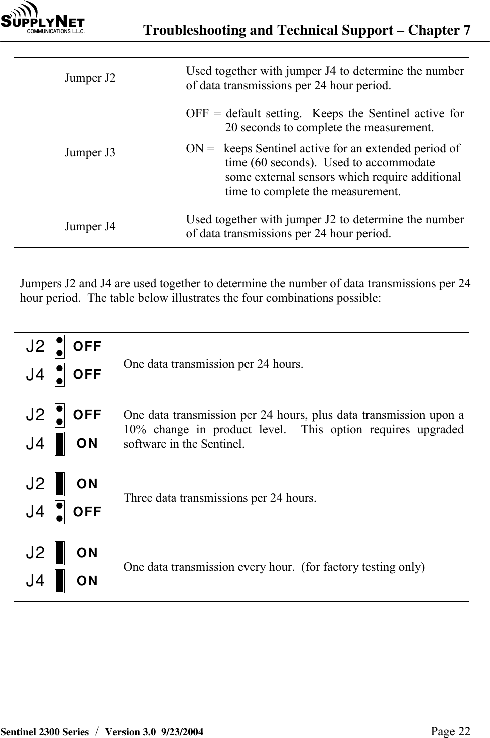
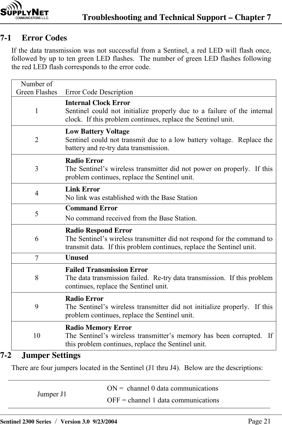
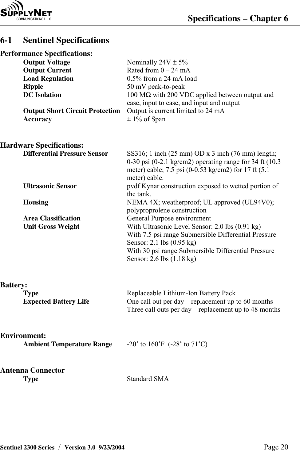
USERS MANUAL
Navigation menu
Upload a User Manual
Namespaces
Wiki Guide
HTML
PDF
Info
Views
User Manual
Discussion / Help
Navigation