Symbol Technologies AP5181D Symbol Access Point User Manual ES3000UserGuide
Symbol Technologies Inc Symbol Access Point ES3000UserGuide
Contents
Manual Part 3 1
AP-51xx Access Point
Product Reference Guide

AP-51xx Access Point
Product Reference Guide
72E-XXXXX-01
Revision X
Juanuary 2007
Pre-Release


© 2006 by Symbol Technologies, Inc. All rights reserved.
No part of this publication may be reproduced or used in any form, or by any electrical or mechanical means,
without permission in writing from Symbol. This includes electronic or mechanical means, such as
photocopying, recording, or information storage and retrieval systems. The material in this manual is subject to
change without notice.
The software is provided strictly on an “as is” basis. All software, including firmware, furnished to the user is
on a licensed basis. Symbol grants to the user a non-transferable and non-exclusive license to use each
software or firmware program delivered hereunder (licensed program). Except as noted below, such license may
not be assigned, sublicensed, or otherwise transferred by the user without prior written consent of Symbol. No
right to copy a licensed program in whole or in part is granted, except as permitted under copyright law. The
user shall not modify, merge, or incorporate any form or portion of a licensed program with other program
material, create a derivative work from a licensed program, or use a licensed program in a network without
written permission from Symbol. The user agrees to maintain Symbol’s copyright notice on the licensed
programs delivered hereunder, and to include the same on any authorized copies it makes, in whole or in part.
The user agrees not to decompile, disassemble, decode, or reverse engineer any licensed program delivered to
the user or any portion thereof.
Symbol reserves the right to make changes to any software or product to improve reliability, function, or design.
Symbol does not assume any product liability arising out of, or in connection with, the application or use of any
product, circuit, or application described herein.
No license is granted, either expressly or by implication, estoppel, or otherwise under any Symbol Technologies,
Inc., intellectual property rights. An implied license only exists for equipment, circuits, and subsystems
contained in Symbol products.
Symbol, Spectrum One, and Spectrum24 are registered trademarks of Symbol Technologies, Inc. Other product
names mentioned in this manual may be trademarks or registered trademarks of their respective companies
and are hereby acknowledged.
Symbol Technologies, Inc.
One Symbol Plaza
Holtsville, New York 11742-1300
http://www.symbol.com


Contents
About This Guide
Introduction. . . . . . . . . . . . . . . . . . . . . . . . . . . . . . . . . . . . . . . . . . . . . . . . . . . . . . . . . vii
Document Conventions. . . . . . . . . . . . . . . . . . . . . . . . . . . . . . . . . . . . . . . . . . . . . . . . vii
Notational Conventions . . . . . . . . . . . . . . . . . . . . . . . . . . . . . . . . . . . . . . . . . . . . . . .viii
Service Information. . . . . . . . . . . . . . . . . . . . . . . . . . . . . . . . . . . . . . . . . . . . . . . . . . .viii
Chapter 1. Introduction
New Features . . . . . . . . . . . . . . . . . . . . . . . . . . . . . . . . . . . . . . . . . . . . . . . . . . . . . . 1-2
Mesh Networking. . . . . . . . . . . . . . . . . . . . . . . . . . . . . . . . . . . . . . . . . . . . . . . 1-2
Additional LAN Subnet. . . . . . . . . . . . . . . . . . . . . . . . . . . . . . . . . . . . . . . . . . . 1-3
On-board Radius Server Authentication. . . . . . . . . . . . . . . . . . . . . . . . . . . . . . 1-4
Hotspot Support . . . . . . . . . . . . . . . . . . . . . . . . . . . . . . . . . . . . . . . . . . . . . . . . 1-4
Routing Information Protocol (RIP) . . . . . . . . . . . . . . . . . . . . . . . . . . . . . . . . . . 1-5
Manual Date and Time Settings. . . . . . . . . . . . . . . . . . . . . . . . . . . . . . . . . . . . 1-5
Feature Overview . . . . . . . . . . . . . . . . . . . . . . . . . . . . . . . . . . . . . . . . . . . . . . . . . . . 1-6

AP-51xx Access Point Product Reference Guide
iv
Single or Dual Mode Radio Options. . . . . . . . . . . . . . . . . . . . . . . . . . . . . . . . . 1-7
Separate LAN and WAN Ports . . . . . . . . . . . . . . . . . . . . . . . . . . . . . . . . . . . . . 1-7
Multiple Mounting Options . . . . . . . . . . . . . . . . . . . . . . . . . . . . . . . . . . . . . . . 1-7
Antenna Support for 2.4 GHz and 5.2 GHz Radios . . . . . . . . . . . . . . . . . . . . . . 1-8
Sixteen Configurable WLANs. . . . . . . . . . . . . . . . . . . . . . . . . . . . . . . . . . . . . . 1-8
Support for 4 BSSIDs per Radio . . . . . . . . . . . . . . . . . . . . . . . . . . . . . . . . . . . . 1-8
Quality of Service (QoS) Support . . . . . . . . . . . . . . . . . . . . . . . . . . . . . . . . . . 1-10
Industry Leading Data Security . . . . . . . . . . . . . . . . . . . . . . . . . . . . . . . . . . . 1-10
Kerberos Authentication. . . . . . . . . . . . . . . . . . . . . . . . . . . . . . . . . . . . . 1-11
EAP Authentication. . . . . . . . . . . . . . . . . . . . . . . . . . . . . . . . . . . . . . . . . 1-11
WEP Encryption . . . . . . . . . . . . . . . . . . . . . . . . . . . . . . . . . . . . . . . . . . . 1-12
KeyGuard Encryption . . . . . . . . . . . . . . . . . . . . . . . . . . . . . . . . . . . . . . . 1-13
Wi-Fi Protected Access (WPA) Using TKIP Encryption . . . . . . . . . . . . . 1-13
WPA2-CCMP (802.11i) Encryption . . . . . . . . . . . . . . . . . . . . . . . . . . . . . 1-13
Firewall Security. . . . . . . . . . . . . . . . . . . . . . . . . . . . . . . . . . . . . . . . . . . 1-14
VPN Tunnels . . . . . . . . . . . . . . . . . . . . . . . . . . . . . . . . . . . . . . . . . . . . . . 1-14
Content Filtering . . . . . . . . . . . . . . . . . . . . . . . . . . . . . . . . . . . . . . . . . . . 1-14
VLAN Support . . . . . . . . . . . . . . . . . . . . . . . . . . . . . . . . . . . . . . . . . . . . . . . . . 1-14
Multiple Management Accessibility Options. . . . . . . . . . . . . . . . . . . . . . . . . 1-15
Updatable Firmware . . . . . . . . . . . . . . . . . . . . . . . . . . . . . . . . . . . . . . . . . . . . 1-15
Programmable SNMP v1/v2/v3 Trap Support . . . . . . . . . . . . . . . . . . . . . . . . 1-15
Power-over-Ethernet Support. . . . . . . . . . . . . . . . . . . . . . . . . . . . . . . . . . . . . 1-16
MU-MU Transmission Disallow . . . . . . . . . . . . . . . . . . . . . . . . . . . . . . . . . . . 1-16
Voice Prioritization . . . . . . . . . . . . . . . . . . . . . . . . . . . . . . . . . . . . . . . . . . . . . 1-17
Support for CAM and PSP MUs . . . . . . . . . . . . . . . . . . . . . . . . . . . . . . . . . . . 1-17
Statistical Displays. . . . . . . . . . . . . . . . . . . . . . . . . . . . . . . . . . . . . . . . . . . . . 1-17
Transmit Power Control . . . . . . . . . . . . . . . . . . . . . . . . . . . . . . . . . . . . . . . . . 1-18
Advanced Event Logging Capability . . . . . . . . . . . . . . . . . . . . . . . . . . . . . . . . 1-18
Configuration File Import/Export Functionality . . . . . . . . . . . . . . . . . . . . . . . 1-18
Default Configuration Restoration . . . . . . . . . . . . . . . . . . . . . . . . . . . . . . . . . 1-18
DHCP Support . . . . . . . . . . . . . . . . . . . . . . . . . . . . . . . . . . . . . . . . . . . . . . . . . 1-19
Multi-Function LEDs . . . . . . . . . . . . . . . . . . . . . . . . . . . . . . . . . . . . . . . . . . . . 1-19
Theory of Operations . . . . . . . . . . . . . . . . . . . . . . . . . . . . . . . . . . . . . . . . . . . . . . . 1-19
Cellular Coverage . . . . . . . . . . . . . . . . . . . . . . . . . . . . . . . . . . . . . . . . . . . . . . 1-20
MAC Layer Bridging . . . . . . . . . . . . . . . . . . . . . . . . . . . . . . . . . . . . . . . . . . . . 1-21
Media Types . . . . . . . . . . . . . . . . . . . . . . . . . . . . . . . . . . . . . . . . . . . . . . . . . . 1-22
Direct-Sequence Spread Spectrum . . . . . . . . . . . . . . . . . . . . . . . . . . . . . . . . 1-22

v
MU Association Process . . . . . . . . . . . . . . . . . . . . . . . . . . . . . . . . . . . . . . . . . 1-23
Operating Modes . . . . . . . . . . . . . . . . . . . . . . . . . . . . . . . . . . . . . . . . . . . . . . . 1-24
Management Access Options . . . . . . . . . . . . . . . . . . . . . . . . . . . . . . . . . . . . . 1-25
Chapter 2. Hardware Installation
Precautions . . . . . . . . . . . . . . . . . . . . . . . . . . . . . . . . . . . . . . . . . . . . . . . . . . . . . . . . 2-2
Available Product Configurations . . . . . . . . . . . . . . . . . . . . . . . . . . . . . . . . . . . . . . . 2-2
AP-5131 Configurations. . . . . . . . . . . . . . . . . . . . . . . . . . . . . . . . . . . . . . . . . . . 2-2
AP-5181 Configurations. . . . . . . . . . . . . . . . . . . . . . . . . . . . . . . . . . . . . . . . . . . 2-4
Requirements. . . . . . . . . . . . . . . . . . . . . . . . . . . . . . . . . . . . . . . . . . . . . . . . . . . . . . . 2-5
Access Point Placement. . . . . . . . . . . . . . . . . . . . . . . . . . . . . . . . . . . . . . . . . . . . . . . 2-5
Site Surveys . . . . . . . . . . . . . . . . . . . . . . . . . . . . . . . . . . . . . . . . . . . . . . . . . . . . 2-6
Antenna Options . . . . . . . . . . . . . . . . . . . . . . . . . . . . . . . . . . . . . . . . . . . . . . . . 2-6
AP-5131 Antenna Options . . . . . . . . . . . . . . . . . . . . . . . . . . . . . . . . . . . . . 2-6
AP-5181 Antenna Options -TBD . . . . . . . . . . . . . . . . . . . . . . . . . . . . . . . . 2-8
Power Options . . . . . . . . . . . . . . . . . . . . . . . . . . . . . . . . . . . . . . . . . . . . . . . . . . . . . . 2-8
AP-5131 Power Options. . . . . . . . . . . . . . . . . . . . . . . . . . . . . . . . . . . . . . . . . . . 2-8
AP-5181 Power Options. . . . . . . . . . . . . . . . . . . . . . . . . . . . . . . . . . . . . . . . . . . 2-8
Symbol Power Injector System . . . . . . . . . . . . . . . . . . . . . . . . . . . . . . . . . . . . . . . . . 2-9
Installing the Power Injector . . . . . . . . . . . . . . . . . . . . . . . . . . . . . . . . . . . . . . . 2-9
Preparing for Site Installation . . . . . . . . . . . . . . . . . . . . . . . . . . . . . . . . . 2-10
Cabling the Power Injector . . . . . . . . . . . . . . . . . . . . . . . . . . . . . . . . . . . 2-10
Power Injector LED Indicators . . . . . . . . . . . . . . . . . . . . . . . . . . . . . . . . . 2-11
Mounting the AP-5131. . . . . . . . . . . . . . . . . . . . . . . . . . . . . . . . . . . . . . . . . . . . . . . 2-12
Desk Mounted Installations. . . . . . . . . . . . . . . . . . . . . . . . . . . . . . . . . . . . . . . 2-12
Wall Mounted Installations. . . . . . . . . . . . . . . . . . . . . . . . . . . . . . . . . . . . . . . 2-14
Suspended Ceiling T-Bar Installations . . . . . . . . . . . . . . . . . . . . . . . . . . . . . . 2-16
Above the Ceiling (Plenum) Installations. . . . . . . . . . . . . . . . . . . . . . . . . . . . . 2-18
AP-5131 LED Indicators . . . . . . . . . . . . . . . . . . . . . . . . . . . . . . . . . . . . . . . . . . . . . . 2-21
Mounting the AP-5181. . . . . . . . . . . . . . . . . . . . . . . . . . . . . . . . . . . . . . . . . . . . . . . 2-23
AP-5181 Pole Mounted Installations. . . . . . . . . . . . . . . . . . . . . . . . . . . . . . . . 2-23
AP-5181 Wall Monuted Installations . . . . . . . . . . . . . . . . . . . . . . . . . . . . . . . 2-24
AP-5181 LED Indicators . . . . . . . . . . . . . . . . . . . . . . . . . . . . . . . . . . . . . . . . . . . . . . 2-25
Setting Up MUs . . . . . . . . . . . . . . . . . . . . . . . . . . . . . . . . . . . . . . . . . . . . . . . . . . . . 2-26

AP-51xx Access Point Product Reference Guide
vi
Chapter 3. Getting Started
Installing the Access Point . . . . . . . . . . . . . . . . . . . . . . . . . . . . . . . . . . . . . . . . . . . . 3-1
Configuration Options. . . . . . . . . . . . . . . . . . . . . . . . . . . . . . . . . . . . . . . . . . . . . . . . 3-2
Basic Device Configuration. . . . . . . . . . . . . . . . . . . . . . . . . . . . . . . . . . . . . . . . . . . . 3-3
Configuring Device Settings. . . . . . . . . . . . . . . . . . . . . . . . . . . . . . . . . . . . . . . 3-5
Configuring WLAN Security Settings. . . . . . . . . . . . . . . . . . . . . . . . . . . . 3-9
Testing Connectivity . . . . . . . . . . . . . . . . . . . . . . . . . . . . . . . . . . . . . . . . . . . . 3-11
Where to Go from Here? . . . . . . . . . . . . . . . . . . . . . . . . . . . . . . . . . . . . . . . . 3-12
Chapter 4. System Configuration
Configuring System Settings . . . . . . . . . . . . . . . . . . . . . . . . . . . . . . . . . . . . . . . . . . 4-2
Configuring Data Access . . . . . . . . . . . . . . . . . . . . . . . . . . . . . . . . . . . . . . . . . . . . . 4-5
Managing Certificate Authority (CA) Certificates . . . . . . . . . . . . . . . . . . . . . . . . . . 4-8
Importing a CA Certificate . . . . . . . . . . . . . . . . . . . . . . . . . . . . . . . . . . . . . . . . 4-8
Creating Self Certificates for Accessing the VPN . . . . . . . . . . . . . . . . . . . . . 4-10
Creating a Certificate for Onboard Radius Authentication . . . . . . . . . . . . . . 4-13
Configuring SNMP Settings . . . . . . . . . . . . . . . . . . . . . . . . . . . . . . . . . . . . . . . . . . 4-17
Configuring SNMP Access Control. . . . . . . . . . . . . . . . . . . . . . . . . . . . . . . . . 4-22
Enabling SNMP Traps. . . . . . . . . . . . . . . . . . . . . . . . . . . . . . . . . . . . . . . . . . . 4-24
Configuring Specific SNMP Traps . . . . . . . . . . . . . . . . . . . . . . . . . . . . . . . . . 4-27
Configuring SNMP RF Trap Thresholds . . . . . . . . . . . . . . . . . . . . . . . . . . . . . 4-29
Configuring Network Time Protocol (NTP) . . . . . . . . . . . . . . . . . . . . . . . . . . . . . . . 4-31
Logging Configuration. . . . . . . . . . . . . . . . . . . . . . . . . . . . . . . . . . . . . . . . . . . . . . . 4-34
Importing/Exporting Configurations . . . . . . . . . . . . . . . . . . . . . . . . . . . . . . . . . . . . 4-36
Updating Device Firmware . . . . . . . . . . . . . . . . . . . . . . . . . . . . . . . . . . . . . . . . . . . 4-40
Upgrade/Downgrade Considerations. . . . . . . . . . . . . . . . . . . . . . . . . . . . . . . 4-45
Chapter 5. Network Management
Configuring the LAN Interface . . . . . . . . . . . . . . . . . . . . . . . . . . . . . . . . . . . . . . . . . 5-1
Configuring VLAN Support . . . . . . . . . . . . . . . . . . . . . . . . . . . . . . . . . . . . . . . . 5-4
Configuring LAN1 and LAN2 Settings . . . . . . . . . . . . . . . . . . . . . . . . . . . . . . . 5-8
Configuring Advanced DHCP Server Settings . . . . . . . . . . . . . . . . . . . . 5-11
Setting the Type Filter Configuration. . . . . . . . . . . . . . . . . . . . . . . . . . . 5-13
Configuring WAN Settings. . . . . . . . . . . . . . . . . . . . . . . . . . . . . . . . . . . . . . . . . . . 5-14
Configuring Network Address Translation (NAT) Settings . . . . . . . . . . . . . . 5-19
Configuring Port Forwarding. . . . . . . . . . . . . . . . . . . . . . . . . . . . . . . . . . 5-21

vii
Enabling Wireless LANs (WLANs). . . . . . . . . . . . . . . . . . . . . . . . . . . . . . . . . . . . . . 5-22
Creating/Editing Individual WLANs. . . . . . . . . . . . . . . . . . . . . . . . . . . . . . . . . 5-24
Configuring WLAN Security Policies. . . . . . . . . . . . . . . . . . . . . . . . . . . . 5-29
Configuring a WLAN Access Control List (ACL) . . . . . . . . . . . . . . . . . . . 5-30
Setting the WLAN Quality of Service (QoS) Policy . . . . . . . . . . . . . . . . . 5-33
Configuring WLAN Hotspot Support . . . . . . . . . . . . . . . . . . . . . . . . . . . . 5-39
Setting the WLAN’s Radio Configuration . . . . . . . . . . . . . . . . . . . . . . . . . . . . 5-44
Configuring the 802.11a or 802.11b/g Radio . . . . . . . . . . . . . . . . . . . . . 5-47
Configuring Bandwidth Management Settings. . . . . . . . . . . . . . . . . . . . . . . . 5-55
Configuring Router Settings . . . . . . . . . . . . . . . . . . . . . . . . . . . . . . . . . . . . . . . . . . 5-57
Setting the RIP Configuration . . . . . . . . . . . . . . . . . . . . . . . . . . . . . . . . . . . . . 5-58
Chapter 6. Configuring Access Point Security
Configuring Security Options. . . . . . . . . . . . . . . . . . . . . . . . . . . . . . . . . . . . . . . . . . . 6-2
Setting Passwords . . . . . . . . . . . . . . . . . . . . . . . . . . . . . . . . . . . . . . . . . . . . . . . . . . . 6-3
Resetting the Access Point Password . . . . . . . . . . . . . . . . . . . . . . . . . . . . . . . . 6-4
Enabling Authentication and Encryption Schemes . . . . . . . . . . . . . . . . . . . . . . . . . . 6-5
Configuring Kerberos Authentication . . . . . . . . . . . . . . . . . . . . . . . . . . . . . . . . . . . . 6-9
Configuring 802.1x EAP Authentication . . . . . . . . . . . . . . . . . . . . . . . . . . . . . . . . . 6-11
Configuring WEP Encryption . . . . . . . . . . . . . . . . . . . . . . . . . . . . . . . . . . . . . . . . . . 6-16
Configuring KeyGuard Encryption . . . . . . . . . . . . . . . . . . . . . . . . . . . . . . . . . . . . . . 6-18
Configuring WPA Using TKIP. . . . . . . . . . . . . . . . . . . . . . . . . . . . . . . . . . . . . . . . . . 6-20
Configuring WPA2-CCMP (802.11i) . . . . . . . . . . . . . . . . . . . . . . . . . . . . . . . . . . . . . 6-22
Configuring Firewall Settings . . . . . . . . . . . . . . . . . . . . . . . . . . . . . . . . . . . . . . . . . 6-25
Configuring LAN to WAN Access . . . . . . . . . . . . . . . . . . . . . . . . . . . . . . . . . . 6-27
Available Protocols . . . . . . . . . . . . . . . . . . . . . . . . . . . . . . . . . . . . . . . . . 6-30
Configuring Advanced Subnet Access. . . . . . . . . . . . . . . . . . . . . . . . . . . . . . . 6-31
Configuring VPN Tunnels. . . . . . . . . . . . . . . . . . . . . . . . . . . . . . . . . . . . . . . . . . . . . 6-33
Configuring Manual Key Settings . . . . . . . . . . . . . . . . . . . . . . . . . . . . . . . . . . 6-37
Configuring Auto Key Settings . . . . . . . . . . . . . . . . . . . . . . . . . . . . . . . . . . . . 6-41
Configuring IKE Key Settings. . . . . . . . . . . . . . . . . . . . . . . . . . . . . . . . . . . . . . 6-43
Viewing VPN Status. . . . . . . . . . . . . . . . . . . . . . . . . . . . . . . . . . . . . . . . . . . . . 6-47
Configuring Content Filtering Settings . . . . . . . . . . . . . . . . . . . . . . . . . . . . . . . . . . 6-49
Configuring Rogue AP Detection . . . . . . . . . . . . . . . . . . . . . . . . . . . . . . . . . . . . . . . 6-52
Moving Rogue APs to the Allowed AP List . . . . . . . . . . . . . . . . . . . . . . . . . . . 6-55
Displaying Rogue AP Details. . . . . . . . . . . . . . . . . . . . . . . . . . . . . . . . . . 6-57

AP-51xx Access Point Product Reference Guide
viii
Using MUs to Detect Rogue Devices . . . . . . . . . . . . . . . . . . . . . . . . . . . . . . . 6-59
Configuring User Authentication . . . . . . . . . . . . . . . . . . . . . . . . . . . . . . . . . . . . . . 6-61
Configuring the Radius Server . . . . . . . . . . . . . . . . . . . . . . . . . . . . . . . . . . . . 6-61
Configuring LDAP Authentication. . . . . . . . . . . . . . . . . . . . . . . . . . . . . . . . . . 6-64
Configuring a Proxy Radius Server . . . . . . . . . . . . . . . . . . . . . . . . . . . . . . . . . 6-66
Managing the Local User Database. . . . . . . . . . . . . . . . . . . . . . . . . . . . . . . . 6-68
Mapping Users to Groups. . . . . . . . . . . . . . . . . . . . . . . . . . . . . . . . . . . . 6-69
Defining the User Access Policy. . . . . . . . . . . . . . . . . . . . . . . . . . . . . . . . . . . 6-70
Chapter 7. Monitoring Statistics
Viewing WAN Statistics. . . . . . . . . . . . . . . . . . . . . . . . . . . . . . . . . . . . . . . . . . . . . . 7-2
Viewing LAN Statistics. . . . . . . . . . . . . . . . . . . . . . . . . . . . . . . . . . . . . . . . . . . . . . . 7-6
Viewing a LAN’s STP Statistics . . . . . . . . . . . . . . . . . . . . . . . . . . . . . . . . . . . . 7-9
Viewing Wireless Statistics . . . . . . . . . . . . . . . . . . . . . . . . . . . . . . . . . . . . . . . . . . 7-11
Viewing WLAN Statistics. . . . . . . . . . . . . . . . . . . . . . . . . . . . . . . . . . . . . . . . 7-13
Viewing Radio Statistics Summary . . . . . . . . . . . . . . . . . . . . . . . . . . . . . . . . . . . . 7-17
Viewing Radio Statistics . . . . . . . . . . . . . . . . . . . . . . . . . . . . . . . . . . . . . . . . 7-18
Retry Histogram . . . . . . . . . . . . . . . . . . . . . . . . . . . . . . . . . . . . . . . . . . . 7-21
Viewing MU Statistics Summary . . . . . . . . . . . . . . . . . . . . . . . . . . . . . . . . . . . . . . 7-23
Viewing MU Details . . . . . . . . . . . . . . . . . . . . . . . . . . . . . . . . . . . . . . . . . . . . 7-24
Pinging Individual MUs. . . . . . . . . . . . . . . . . . . . . . . . . . . . . . . . . . . . . . . . . . 7-27
MU Authentication Statistics. . . . . . . . . . . . . . . . . . . . . . . . . . . . . . . . . . . . . 7-28
Viewing the Mesh Statistics Summary . . . . . . . . . . . . . . . . . . . . . . . . . . . . . . . . . 7-29
Viewing Known Access Point Statistics. . . . . . . . . . . . . . . . . . . . . . . . . . . . . . . . . 7-30
Chapter 8. Command Line Interface Reference
Connecting to the CLI . . . . . . . . . . . . . . . . . . . . . . . . . . . . . . . . . . . . . . . . . . . . . . . . 8-1
Accessing the CLI through the Serial Port . . . . . . . . . . . . . . . . . . . . . . . . . . . . 8-1
Accessing the CLI via Telnet . . . . . . . . . . . . . . . . . . . . . . . . . . . . . . . . . . . . . . 8-2
Admin and Common Commands . . . . . . . . . . . . . . . . . . . . . . . . . . . . . . . . . . . . . . . 8-3
Network Commands . . . . . . . . . . . . . . . . . . . . . . . . . . . . . . . . . . . . . . . . . . . . . . . . 8-11
Network LAN Commands . . . . . . . . . . . . . . . . . . . . . . . . . . . . . . . . . . . . . . . . 8-12
Network LAN, Bridge Commands. . . . . . . . . . . . . . . . . . . . . . . . . . . . . . 8-16
Network LAN, WLAN-Mapping Commands . . . . . . . . . . . . . . . . . . . . . 8-19
Network LAN, DHCP Commands . . . . . . . . . . . . . . . . . . . . . . . . . . . . . . 8-28
Network Type Filter Commands. . . . . . . . . . . . . . . . . . . . . . . . . . . . . . . 8-34

ix
Network WAN Commands . . . . . . . . . . . . . . . . . . . . . . . . . . . . . . . . . . . . . . . 8-39
Network WAN NAT Commands . . . . . . . . . . . . . . . . . . . . . . . . . . . . . . . 8-42
Network WAN, VPN Commands . . . . . . . . . . . . . . . . . . . . . . . . . . . . . . . 8-48
Network Wireless Commands. . . . . . . . . . . . . . . . . . . . . . . . . . . . . . . . . . . . . 8-57
Network WLAN Commands . . . . . . . . . . . . . . . . . . . . . . . . . . . . . . . . . . 8-58
Network Security Commands . . . . . . . . . . . . . . . . . . . . . . . . . . . . . . . . . 8-71
Network ACL Commands. . . . . . . . . . . . . . . . . . . . . . . . . . . . . . . . . . . . . 8-80
Network Radio Configuration Commands. . . . . . . . . . . . . . . . . . . . . . . . 8-85
Network Quality of Service (QoS) Commands. . . . . . . . . . . . . . . . . . . . 8-102
Network Bandwith Management Commands. . . . . . . . . . . . . . . . . . . . 8-107
Network Rogue-AP Commands . . . . . . . . . . . . . . . . . . . . . . . . . . . . . . . 8-110
Network Firewall Commands . . . . . . . . . . . . . . . . . . . . . . . . . . . . . . . . . . . . 8-120
Network Router Commands. . . . . . . . . . . . . . . . . . . . . . . . . . . . . . . . . . . . . . 8-125
System Commands . . . . . . . . . . . . . . . . . . . . . . . . . . . . . . . . . . . . . . . . . . . . . . . . 8-131
System Debug and Last Password Commands . . . . . . . . . . . . . . . . . . . . . . . 8-135
System Access Commands . . . . . . . . . . . . . . . . . . . . . . . . . . . . . . . . . . . . . . 8-136
System Certificate Management Commands . . . . . . . . . . . . . . . . . . . . . . . . 8-139
System SNMP Commands. . . . . . . . . . . . . . . . . . . . . . . . . . . . . . . . . . . . . . . 8-152
System SNMP Access Commands . . . . . . . . . . . . . . . . . . . . . . . . . . . . 8-153
System SNMP Traps Commands. . . . . . . . . . . . . . . . . . . . . . . . . . . . . . 8-158
System Network Time Protocol (NTP) Commands . . . . . . . . . . . . . . . . . . . . 8-164
System Log Commands . . . . . . . . . . . . . . . . . . . . . . . . . . . . . . . . . . . . . . . . . 8-169
System Configuration-Update Commands . . . . . . . . . . . . . . . . . . . . . . . . . . 8-175
Firmware Update Commands . . . . . . . . . . . . . . . . . . . . . . . . . . . . . . . . . . . . 8-182
Statistics Commands . . . . . . . . . . . . . . . . . . . . . . . . . . . . . . . . . . . . . . . . . . . . . . . 8-186
Chapter 9. Configuring Mesh Networking
Mesh Networking Overview . . . . . . . . . . . . . . . . . . . . . . . . . . . . . . . . . . . . . . . . . . . 9-1
The AP-51xx Client Bridge Association Process . . . . . . . . . . . . . . . . . . . . . . . . 9-3
Spanning Tree Protocol (STP) . . . . . . . . . . . . . . . . . . . . . . . . . . . . . . . . . . . . . . 9-4
Defining the Mesh Topology . . . . . . . . . . . . . . . . . . . . . . . . . . . . . . . . . . . . . . . 9-4
Mesh Networking and the AP-51xx’s Two Subnets . . . . . . . . . . . . . . . . . . . . . 9-5
Normal Operation . . . . . . . . . . . . . . . . . . . . . . . . . . . . . . . . . . . . . . . . . . . . . . . 9-5
Impact of Importing/Exporting Configurations to a Mesh Network . . . . . . . . . 9-5
Configuring Mesh Networking Support. . . . . . . . . . . . . . . . . . . . . . . . . . . . . . . . . . . 9-6
Setting the LAN Configuration for Mesh Networking Support. . . . . . . . . . . . . 9-6

AP-51xx Access Point Product Reference Guide
x
Configuring a WLAN for Mesh Networking Support . . . . . . . . . . . . . . . . . . . . 9-8
Configuring the Access Point Radio for Mesh Support . . . . . . . . . . . . . . . . . 9-12
Usage Scenario - Trion Enterprises . . . . . . . . . . . . . . . . . . . . . . . . . . . . . . . . . . . . 9-19
Trion’s Initial Deployment . . . . . . . . . . . . . . . . . . . . . . . . . . . . . . . . . . . . . . . 9-19
Adding 2 Client Bridges to Expand the Coverage Area . . . . . . . . . . . . . . . . . 9-30
Adding 2 More Client Bridges to the Trion Network . . . . . . . . . . . . . . . . . . . 9-37
Appendix A. Technical Specifications
Physical Characteristics . . . . . . . . . . . . . . . . . . . . . . . . . . . . . . . . . . . . . . . . . . . . . . A-2
AP-5131 Physical Characteristics. . . . . . . . . . . . . . . . . . . . . . . . . . . . . . . . . . . A-2
AP-5181 Physical Characteristics. . . . . . . . . . . . . . . . . . . . . . . . . . . . . . . . . . . A-3
Electrical Characteristics . . . . . . . . . . . . . . . . . . . . . . . . . . . . . . . . . . . . . . . . . . . . . A-4
Radio Characteristics . . . . . . . . . . . . . . . . . . . . . . . . . . . . . . . . . . . . . . . . . . . . . . . . A-4
Antenna Specifications. . . . . . . . . . . . . . . . . . . . . . . . . . . . . . . . . . . . . . . . . . . . . . . A-5
AP-5131 Antenna Specifications . . . . . . . . . . . . . . . . . . . . . . . . . . . . . . . . . . . A-5
2.4 GHz Antenna Matrix. . . . . . . . . . . . . . . . . . . . . . . . . . . . . . . . . . . . . . A-5
5.2 GHz Antenna Matrix. . . . . . . . . . . . . . . . . . . . . . . . . . . . . . . . . . . . . . A-5
AP-5131 Additional Antenna Components. . . . . . . . . . . . . . . . . . . . . . . . A-6
AP-5131 Antenna Accessory Connectors, Cable Type and Length . . . . . A-6
AP-5181 Antenna Specifications . . . . . . . . . . . . . . . . . . . . . . . . . . . . . . . . . . . A-7
Country Codes. . . . . . . . . . . . . . . . . . . . . . . . . . . . . . . . . . . . . . . . . . . . . . . . . . . . . . A-7
Appendix B. Usage Scenarios
Configuring Automatic Updates using a DHCP or Linux BootP Server ConfigurationB-1
Windows - DHCP Server Configuration . . . . . . . . . . . . . . . . . . . . . . . . . . . . . . B-2
Embedded Options - Using Option 43 . . . . . . . . . . . . . . . . . . . . . . . . . . . B-2
Global Options - Using Extended/Standard Options . . . . . . . . . . . . . . . . B-3
DHCP Priorities . . . . . . . . . . . . . . . . . . . . . . . . . . . . . . . . . . . . . . . . . . . . . B-5
Linux - BootP Server Configuration . . . . . . . . . . . . . . . . . . . . . . . . . . . . . . . . . B-6
BootP Options . . . . . . . . . . . . . . . . . . . . . . . . . . . . . . . . . . . . . . . . . . . . . . B-6
BootP Priorities. . . . . . . . . . . . . . . . . . . . . . . . . . . . . . . . . . . . . . . . . . . . . B-8
Configuring an IPSEC Tunnel and VPN FAQs . . . . . . . . . . . . . . . . . . . . . . . . . . . . . . B-8
Configuring a VPN Tunnel Between Two Access Points . . . . . . . . . . . . . . . . . B-8
Configuring a Cisco VPN Device. . . . . . . . . . . . . . . . . . . . . . . . . . . . . . . . . . . B-12

xi
Frequently Asked VPN Questions . . . . . . . . . . . . . . . . . . . . . . . . . . . . . . . . . .B-13
Replacing an AP-4131 with an AP-5131 or AP-5181. . . . . . . . . . . . . . . . . . . . . . . .B-18
Appendix C. Customer Support
Index

AP-51xx Access Point Product Reference Guide
xii

About This Guide
Introduction
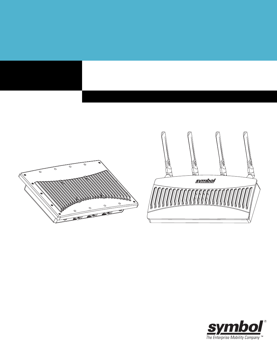
This guide provides configuration and setup information for the AP-5131 and AP-5181 model
access points. For the purposes of this guide, the devices will be called AP-51xx or the generic
term “access point” when an identical conifiguration activities applied to both models.
Document Conventions
The following document conventions are used in this document:
NOTE Indicate tips or special requirements.

AP-51xx Access Point Product Reference Guide
viii
Notational Conventions
The following notational conventions are used in this document:
• Italics are used to highlight specific items in the general text, and to identify chapters and
sections in this and related documents.
• Bullets (•) indicate:
• action items
• lists of alternatives
• lists of required steps that are not necessarily sequential
• Sequential lists (those describing step-by-step procedures) appear as numbered lists.
Service Information
If a problem is encountered with the access point, contact the Symbol Customer Support. Refer to
Appendix C for contact information. Before calling, have the model number and serial number at hand.
If the problem cannot be solved over the phone, you may need to return your equipment for servicing.
If that is necessary, you will be given specific instructions.
Symbol Technologies is not responsible for any damages incurred during shipment if the
approved shipping container is not used. Shipping the units improperly can possibly void
the warranty. If the original shipping container was not kept, contact Symbol to have
another sent to you.
CAUTION Indicates conditions that can cause equipment damage or data loss.
WARNING! Indicates a condition or procedure that could result in personal injury or
equipment damage.
!

Introduction
This AP-51xx Product Reference Guide contains setup and advanced configuration instructions for
both the AP-5131 and AP-5181 model Symbol access points. Both the AP-5131 and AP-5181 model
access points share the same Web UI interface, thus there is no difference in how the devices are
configured using the instructions within this guide. However, there are marked differences in how the
devices are physically installed, as the AP-5181 is constructed to support outdoor installations, while
the AP-5131 model is constructed primarily for indoor deployments.
The access point (AP) provides a bridge between Ethernet wired LANs or WANs and wireless
networks. It provides connectivity between Ethernet wired networks and radio-equipped mobile units
(MUs). MUs include the full line of Symbol terminals, bar-code scanners, adapters (PC cards, Compact
Flash cards and PCI adapters) and other devices.
The access point provides a maximum 54Mbps data transfer rate via each radio. It monitors Ethernet
traffic and forwards appropriate Ethernet messages to MUs over the network. It also monitors MU
radio traffic and forwards MU packets to the Ethernet LAN.
If you are new to using an access point for managing your network, refer to Theory of Operations on
page 1-19 for an overview on wireless networking fundamentals.

AP-51xx Access Point Product Reference Guide
1-2
1.1 New Features
With this most recent 1.1 release of the access point firmware, the following new features have been
introduced to the existing feature set:
•Mesh Networking
•Additional LAN Subnet
•On-board Radius Server Authentication
•Hotspot Support
•Routing Information Protocol (RIP)
•Manual Date and Time Settings
1.1.1 Mesh Networking
Utilize the new mesh networking functionality to allow the access point to function as a bridge to
connect two Ethernet networks or as a repeater to extend your network’s coverage area without
additional cabling. Mesh networking is configurable in two modes. It can be set in a wireless client
bridge mode and/or a wireless base bridge mode (which accepts connections from client bridges).
These two modes are not mutually exclusive.
In client bridge mode, the access point scans to find other access points using the selected WLAN’s
ESSID. The access point must go through the association and authentication process to establish a
wireless connection. The mesh networking association process is identical to the access point’s MU
association process. Once the association/authentication process is complete, the wireless client
adds the connection as a port on its bridge module. This causes the access point (in client bridge
mode) to begin forwarding configuration packets to the base bridge. An access point in base bridge
mode allows the access point radio to accept client bridge connections.
The two bridges communicate using the Spanning Tree Protocol (STP). The spanning tree determines
the path to the root and detects if the current connection is part of a network loop with another
connection. Once the spanning tree converges, both access points begin learning which destinations
reside on which side of the network. This allows them to forward traffic intelligently.
After the access point (in client bridge mode) establishes at least one wireless connection, it will
begin beaconing and accepting wireless connections (if configured to support mobile users). If the
access point is configured as both a client bridge and a base bridge, it begins accepting client bridge
connections. In this way, the mesh network builds itself over time and distance.

Introduction 1-3
Once the access point (in client bridge mode) establishes at least one wireless connection, it
establishes other wireless connections in the background as they become available. In this way, the
access point is able to establish simultaneous redundant links. An access point (in client bridge mode)
can establish up to 3 simultaneous wireless connections with other AP-5131s or AP-5181s. A client
bridge always initiates the connections and the base bridge is always the acceptor of the mesh
network data proliferating the network.
Since each access point can establish up to 3 simultaneous wireless connections, some of these
connections may be redundant. In that case, the STP algorithm establishes which links are the
redundant links and disables the links from forwarding.
For an overview on mesh networking as well as details on configuring the access point’s mesh
networking functionality, see Configuring Mesh Networking on page 9-1.
1.1.2 Additional LAN Subnet
In a typical retail or small office environment (wherein a wireless network is available along with a
production WLAN) it is frequently necessary to segment a LAN into two subnets. Consequently, a
second LAN is necessary to “segregate” wireless traffic.
The access point now has a second LAN subnet enabling administrators to segment the access
point’s LAN connection into two separate networks. The main access point LAN screen now allows
the user to select either LAN1 or LAN2 as the active LAN over the access point’s Ethernet port. Both
LANs can still be active at any given time, but only one can transmit over the access point physical
LAN connection. Each LAN has a separate configuration screen (called LAN 1 and LAN 2 by default)
accessible under the main LAN screen. The user can rename each LAN as necessary. Additionally,
each LAN can have its own Ethernet Type Filter configuration, and subnet access (HTTP, SSH, SNMP
and telnet) configuration.
For detailed information on configuring the access point for additional LAN subnet support, see
Configuring the LAN Interface on page 5-1.

AP-51xx Access Point Product Reference Guide
1-4
1.1.3 On-board Radius Server Authentication
The access point now has the ability to work as a Radius Server to provide user database information
and user authentication. Several new screens have been added to the access point’s menu tree to
configure Radius server authentication and configure the local user database and access policies. A
new Radius Server screen allows an administrator to define the data source, authentication type and
associate digital certificates with the authentication scheme. The LDAP screen allows the
administrator to configure an external LDAP Server for use with the access point. A new Access Policy
screen enables the administrator to set WLAN access based on user groups defined within the User
Database screen. Each user is authorized based on the access policies applicable to that user. Access
policies allow an administrator to control access to a user groups based on the WLAN configurations.
For detailed information on configuring the access point for AAA Radius Server support, see
Configuring User Authentication on page 6-61.
1.1.4 Hotspot Support
The access point now allows hotspot operators to provide user authentication and accounting
without a special client application. The access point uses a traditional Internet browser as a secure
authentication device. Rather than rely on built-in 802.11security features to control access point
association privileges, you can configure a WLAN with no WEP (an open network). The access point
issues an IP address to the user using a DHCP server, authenticates the user and grants the user to
access the Internet.
If a tourist visits a public hotspot and wants to browse a Web page, they boot their laptop and
associate with a local Wi-Fi network by entering a valid SSID. They start a browser, and the hotspot’s
access controller forces the un-authenticated user to a Welcome page (from the hotspot operator)
that allows the user to login with a username and password. In order to send a redirected page (a
login page), a TCP termination exists locally on the access point. Once the login page displays, the
user enters their credentials. The access point connects to the Radius server and determines the
identity of the connected wireless user. Thus, allowing the user to access the Internet once
successfully authenticated.
For detailed information on configuring the access point for Hotspot support, see
Configuring WLAN Hotspot Support on page 5-39.

Introduction 1-5
1.1.5 Routing Information Protocol (RIP)
With the release of the 1.1 version access point, Routing Information Protocol (RIP) functionality has
been added to the existing Router screen. RIP is an interior gateway protocol that specifies how
routers exchange routing-table information. The parent Router screen also allows the administrator
to select the type of RIP and the type of RIP authentication used.
For detailed information on configuring RIP functionality as part of the access point’s Router
functionality, see Setting the RIP Configuration on page 5-58.
1.1.6 Manual Date and Time Settings
As an alternative to defining a NTP server to provide access point system time, the access point can
now have its date and time set manually. A new Manual Date/Time Setting screen can be used to set
the access point time using a Year-Month-Day HH:MM:SS format.
For detailed information on manually setting the access point’s system time, see Configuring Network
Time Protocol (NTP) on page 4-31.

AP-51xx Access Point Product Reference Guide
1-6
1.2 Feature Overview
The Symbol access point has the following existing features carried forward from its initial 1.0
release:
•Single or Dual Mode Radio Options
•Separate LAN and WAN Ports
•Multiple Mounting Options
•Antenna Support for 2.4 GHz and 5.2 GHz Radios
•Sixteen Configurable WLANs
•Support for 4 BSSIDs per Radio
•Quality of Service (QoS) Support
•Industry Leading Data Security
•VLAN Support
•Multiple Management Accessibility Options
•Updatable Firmware
•Programmable SNMP v1/v2/v3 Trap Support
•Power-over-Ethernet Support
•MU-MU Transmission Disallow
•Voice Prioritization
•Support for CAM and PSP MUs
•Statistical Displays
•Transmit Power Control
•Advanced Event Logging Capability
•Configuration File Import/Export Functionality
•Default Configuration Restoration
•DHCP Support
•Multi-Function LEDs

Introduction 1-7
1.2.1 Single or Dual Mode Radio Options
One or two possible configurations are available on the access point depending on which model is
purchased. If the access point is manufactured as a single radio access point, the access point
enables you to configure the single radio for either 802.11a or 802.11b/g.
If the access point is manufactured as a dual-radio access point, the access point enables you to
configure one radio for 802.11a, and the other 802.11b/g.
For detailed information on configuring your access point, see Setting the WLAN’s Radio
Configuration on page 5-44.
1.2.2 Separate LAN and WAN Ports
The access point has one LAN port and one WAN port, each with their own MAC address. The access
point must manage all data traffic over the LAN connection carefully as either a DHCP client, BOOTP
client, DHCP server or using a static IP address. The access point can only use a Power-over-Ethernet
device when connected to the LAN port.
For detailed information on configuring the access point LAN port, see Configuring the LAN Interface
on page 5-1.
A Wide Area Network (WAN) is a widely dispersed telecommunications network. In a corporate
environment, the WAN port might connect to a larger corporate network. For a small business, the
WAN port might connect to a DSL or cable modem to access the Internet. Regardless, network
address information must be configured for the access point’s intended mode of operation.
For detailed information on configuring the access point’s WAN port, see Configuring WAN Settings
on page 5-14.
The LAN and WAN port MAC addresses can be located within the LAN and WAN Stats screens.
For detailed information on locating the access point MAC addresses, see Viewing WAN Statistics
on page 7-2 and Viewing LAN Statistics on page 7-6.
1.2.3 Multiple Mounting Options
The access point rests on a flat surface, attaches to a wall, mounts under a ceiling or above a ceiling
(attic). Choose a mounting option based on the physical environment of the coverage area. Do not
mount the access point in a location that has not been approved in an access point radio coverage
site survey.

AP-51xx Access Point Product Reference Guide
1-8
For detailed information on the mounting options available for the access point, see
Mounting the AP-5131 on page 2-12.
1.2.4 Antenna Support for 2.4 GHz and 5.2 GHz Radios
The access point supports several 802.11a and 802.11b/g radio antennas. Select the antenna best
suited to the radio transmission requirements of your coverage area.
For an overview of the Radio 1 (2.4 GHz) and Radio 2 (5.2 GHz) antennas supported on the access
point’s Reverse SMA (RSMA) connectors, see Antenna Specifications on page A-5.
1.2.5 Sixteen Configurable WLANs
A Wireless Local Area Network (WLAN) is a data-communications system that flexibly extends the
functionalities of a wired LAN. A WLAN does not require lining up devices for line-of-sight
transmission, and are thus, desirable for wireless networking. Roaming users can be handed off from
one access point to another like a cellular phone system. WLANs can therefore be configured around
the needs of specific groups of users, even when they are not in physical proximity. Sixteen WLANs
are configurable on each access point.
To enable and configure WLANs on an access point radio, see Enabling Wireless LANs (WLANs) on
page 5-22.
1.2.6 Support for 4 BSSIDs per Radio
The access point supports four BSSIDs per radio. Each BSSID has a corresponding MAC address. The
first MAC address corresponds to BSSID #1. The MAC addresses for the other three BSSIDs (BSSIDs
#2, #3, #4) are derived by adding 1, 2, 3, respectively, to the radio MAC address.
If the radio MAC address displayed on the Radio Settings screen is 00:A0:F8:72:20:DC, then the
BSSIDs for that radio will have the following MAC addresses:
BSSID MAC Address Hexadecimal Addition
BSSID #1 00:A0:F8:72:20:DC Same as Radio MAC address
BSSID #2 00:A0:F8:72:20:DD Radio MAC address +1
BSSID #3 00:A0:F8:72:20:DE Radio MAC address +2
BSSID #4 00:A0:F8:72:20:DF Radio MAC address +3

Introduction 1-9
For detailed information on strategically mapping BSSIDs to WLANs, see Configuring the 802.11a or
802.11b/g Radio on page 5-47.

AP-51xx Access Point Product Reference Guide
1-10
1.2.7 Quality of Service (QoS) Support
The access point QoS implementation provides applications running on different wireless devices a
variety of priority levels to transmit data to and from the access point. Equal data transmission priority
is fine for data traffic from applications such as Web browsers, file transfers or email, but is
inadequate for multimedia applications.
Voice over Internet Protocol (VoIP), video streaming and interactive gaming are highly sensitive to
latency increases and throughput reductions. These forms of higher priority data traffic can
significantly benefit from the access point QoS implementation.The WiFi Multimedia QOS Extensions
(WMM) implementation used by the access point shortens the time between transmitting higher
priority data traffic and is thus desirable for multimedia applications. In addition, U-APSD (WMM
Power Save) is also supported.
WMM defines four access categories—voice, video, best effort and background—to prioritize traffic
for providing enhanced multimedia support.
For detailed information on configuring QoS support for the access point, see Setting the WLAN
Quality of Service (QoS) Policy on page 5-33.
1.2.8 Industry Leading Data Security
The access point supports numerous encryption and authentication techniques to protect the data
transmitting on the WLAN.
The following authentication techniques are supported on the access point:
•Kerberos Authentication
•EAP Authentication
The following encryption techniques are supported on the access point:
•WEP Encryption
•KeyGuard Encryption
•Wi-Fi Protected Access (WPA) Using TKIP Encryption
•WPA2-CCMP (802.11i) Encryption
In addition, the access point supports the following additional security features:
•Firewall Security
•VPN Tunnels

Introduction 1-11
•Content Filtering
For an overview on the encryption and authentication schemes available on the access point, refer to
Configuring Access Point Security on page 6-1.
1.2.8.1 Kerberos Authentication
Authentication is a means of verifying information that is transmitted from a secure source. If
information is authentic, you know who created it and you know that it has not been altered in any
way since it was originated. Authentication entails a network administrator employing a software
“supplicant” on their computer or wireless device.
Authentication is critical for the security of any wireless LAN device. Traditional authentication
methods are not suitable for use in wireless networks where an unauthorized user can monitor
network traffic and intercept passwords. The use of strong authentication methods that do not
disclose passwords is necessary. Symbol uses the Kerberos authentication service protocol (specified
in RFC 1510), to authenticate users/clients in a wireless network environment and to securely
distribute the encryption keys used for both encrypting and decrypting.
A basic understanding of RFC 1510 Kerberos Network Authentication Service (V5) is helpful in
understanding how Kerberos functions. By default, WLAN devices operate in an open system network
where any wireless device can associate with an AP without authorization. Kerberos requires device
authentication before access to the wired network is permitted.
For detailed information on Kerbeors configurations, see Configuring Kerberos Authentication on
page 6-9.
1.2.8.2 EAP Authentication
The Extensible Authentication Protocol (EAP) feature provides access points and their associated
MU’s an additional measure of security for data transmitted over the wireless network. Using EAP,
authentication between devices is achieved through the exchange and verification of certificates.
EAP is a mutual authentication method whereby both the MU and AP are required to prove their
identities. Like Kerberos, the user loses device authentication if the server cannot provide proof of
device identification
Using EAP, a user requests connection to a WLAN through the access point. The access point then
requests the identity of the user and transmits that identity to an authentication server. The server
prompts the AP for proof of identity (supplied to the access point by the user) and then transmits the
user data back to the server to complete the authentication.

AP-51xx Access Point Product Reference Guide
1-12
An MU is not able to access the network if not authenticated. When configured for EAP support, the
access point displays the MU as an EAP station.
EAP is only supported on mobile devices running Windows XP, Windows 2000 (using Service Pack #4)
and Windows Mobile 2003. Refer to the system administrator for information on configuring a Radius
Server for EAP (802.1x) support.
For detailed information on EAP configurations, see Configuring 802.1x EAP Authentication on page
6-11.
1.2.8.3 WEP Encryption
All WLAN devices face possible information theft. Theft occurs when an unauthorized user
eavesdrops to obtain information illegally. The absence of a physical connection makes wireless links
particularly vulnerable to this form of theft. Most forms of WLAN security rely on encryption to
various extents. Encryption entails scrambling and coding information, typically with mathematical
formulas called algorithms, before the information is transmitted. An algorithm is a set of instructions
or formula for scrambling the data. A key is the specific code used by the algorithm to encrypt or
decrypt the data. Decryption is the decoding and unscrambling of received encrypted data.
The same device, host computer or front-end processor, usually performs both encryption and
decryption. The data transmit or receive direction determines whether the encryption or decryption
function is performed. The device takes plain text, encrypts or scrambles the text typically by
mathematically combining the key with the plain text as instructed by the algorithm, then transmits
the data over the network. At the receiving end, another device takes the encrypted text and decrypts,
or unscrambles, the text revealing the original message. An unauthorized user can know the
algorithm, but cannot interpret the encrypted data without the appropriate key. Only the sender and
receiver of the transmitted data know the key.
Wired Equivalent Privacy (WEP) is an encryption security protocol specified in the IEEE Wireless
Fidelity (Wi-Fi) standard, 802.11b and supported by the access point AP. WEP encryption is designed
to provide a WLAN with a level of security and privacy comparable to that of a wired LAN. The level
of protection provided by WEP encryption is determined by the encryption key length and algorithm.
An encryption key is a string of case sensitive characters used to encrypt and decrypt data packets
transmitted between a mobile unit (MU) and the access point. An access point and associated
wireless clients must use the same encryption key (typically 1 through 4) to interoperate.
For detailed information on WEP configurations, see Configuring WEP Encryption on page 6-16.

Introduction 1-13
1.2.8.4 KeyGuard Encryption
Use KeyGuard to shield the master encryption keys from being discovered through hacking. KeyGuard
negotiation takes place between the access point and MU upon association. The access point can
use KeyGuard with Symbol MUs. KeyGuard is only supported on Symbol MUs making it a Symbol
proprietary security mechanism.
For detailed information on KeyGuard configurations, see Configuring KeyGuard Encryption on page
6-18.
1.2.8.5 Wi-Fi Protected Access (WPA) Using TKIP Encryption
Wi-Fi Protected Access (WPA) is a security standard for systems operating with a Wi-Fi wireless
connection. WEP’s lack of user authentication mechanisms is addressed by WPA. Compared to WEP,
WPA provides superior data encryption and user authentication.
WPA addresses the weaknesses of WEP by including:
• a per-packet key mixing function
• a message integrity check
• an extended initialization vector with sequencing rules
• a re-keying mechanism
WPA uses an encryption method called Temporal Key Integrity Protocol (TKIP). WPA employs 802.1X
and Extensible Authentication Protocol (EAP).
For detailed information on WPA using TKIP configurations, see Configuring WPA Using TKIP on page
6-20.
1.2.8.6 WPA2-CCMP (802.11i) Encryption
WPA2 is a newer 802.11i standard that provides even stronger wireless security than Wi-Fi Protected
Access (WPA) and WEP. Counter-mode/CBC-MAC Protocol (CCMP) is the security standard used by
the Advanced Encryption Standard (AES). AES serves the same function TKIP does for WPA-TKIP.
CCMP computes a Message Integrity Check (MIC) using the proven Cipher Block Message
Authentication Code (CBC-MAC) technique. Changing just one bit in a message produces a totally
different result.
WPA2-CCMP is based on the concept of a Robust Security Network (RSN), which defines a hierarchy
of keys with a limited lifetime (similar to TKIP). Like TKIP, the keys the administrator provides are used
to derive other keys. Messages are encrypted using a 128-bit secret key and a 128-bit block of data.
the end result is an encryption scheme as secure as any the access point provides.

AP-51xx Access Point Product Reference Guide
1-14
For detailed information on WPA2-CCMP configurations, see Configuring WPA2-CCMP (802.11i) on
page 6-22.
1.2.8.7 Firewall Security
A firewall keeps personal data in and hackers out. The access point firewall prevents suspicious
Internet traffic from proliferating the access point managed network. The access point performs
network address translation (NAT) on packets passing to and from the WAN port. This combination
provides enhanced security by monitoring communication with the wired network.
For detailed information on configuring the access point firewall, see Configuring Firewall Settings
on page 6-25.
1.2.8.8 VPN Tunnels
Virtual Private Networks (VPNs) are IP-based networks using encryption and tunneling providing
users remote access to a secure LAN. In essence, the trust relationship is extended from one LAN
across the public network to another LAN, without sacrificing security. A VPN behaves like a private
network; however, because the data travels through the public network, it needs several layers of
security. The access point can function as a robust VPN gateway.
For detailed information on configuring VPN security support, see Configuring VPN Tunnels on page
6-33.
1.2.8.9 Content Filtering
Content filtering allows system administrators to block specific commands and URL extensions from
going out through the access point WAN port only. Therefore, content filtering affords system
administrators selective control on the content proliferating the network and is a powerful screening
tool. Content filtering allows the blocking of up to 10 files or URL extensions and allows blocking of
specific outbound HTTP, SMTP, and FTP requests.
For detailed information on configuring content filtering support, see Configuring Content Filtering
Settings on page 6-49.
1.2.9 VLAN Support
A Virtual Local Area Network (VLAN) is a means to electronically separate data on the same access
point from a single broadcast domain into separate broadcast domains. By using a VLAN, you can
group by logical function instead of physical location. There are 16 VLANs supported on the access
point. An administrator can map up to 16 WLANs to 16 VLANs and enable or disable dynamic VLAN

Introduction 1-15
assignment. In addition to these 16 VLANs, the access point supports dynamic, user-based, VLANs
when using EAP authentication.
VLANs enable organizations to share network resources in various network segments within large
areas (airports, shopping malls, etc.). A VLAN is a group of clients with a common set of requirements
independent of their physical location. VLANs have the same attributes as physical LANs, but they
enable administrators to group clients even when they are not members of the same network
segment.
For detailed information on configuring VLAN support, see Configuring VLAN Support on page 5-4.
1.2.10 Multiple Management Accessibility Options
The access point can be accessed and configured using one of the following methods:
• Java-Based Web UI
• Human readable config file (imported via FTP or TFTP)
• MIB (Management Information Base)
•Command Line Interface (CLI) accessed via RS-232 or Telnet. Use the access point DB-9
serial port for direct access to the command-line interface from a PC. Use Symbol's Null-
Modem cable (Part No. 25-632878-0) for the best fitting connection.
1.2.11 Updatable Firmware
Symbol periodically releases updated versions of the access point device firmware to the Symbol
Web site. If the access point firmware version displayed on the System Settings page (see
Configuring System Settings on page 4-2) is older than the version on the Web site, Symbol
recommends updating the access point to the latest firmware version for full feature functionality.
For detailed information on updating the access point firmware using FTP or TFTP, see Updating
Device Firmware on page 4-40.
1.2.12 Programmable SNMP v1/v2/v3 Trap Support
Simple Network Management Protocol (SNMP) facilitates the exchange of management information
between network devices. SNMP uses Management Information Bases (MIBs) to manage the device
configuration and monitor Internet devices in remote locations. MIB information accessed via SNMP
is defined by a set of managed objects called object identifiers (OIDs). An object identifier (OID) is
used to uniquely identify each object variable of a MIB.

AP-51xx Access Point Product Reference Guide
1-16
SNMP allows a network administrator to configure the access point, manage network performance,
find and solve network problems, and plan for network growth. The access point supports SNMP
management functions for gathering information from its network components. The access point
downloads site contains the following 2 MIB files:
• Symbol-CC-WS2000-MIB-2.0 (standard Symbol MIB file)
• Symbol-AP-5131-MIB (AP-5131 and AP-5181 specific MIB file)
The access point SNMP agent functions as a command responder and is a multilingual agent
responding to SNMPv1, v2c and v3 managers (command generators). The factory default
configuration maintains SNMPv1/2c support of the community names, hence providing backward
compatibility.
For detailed information on configuring SNMP traps, see Configuring SNMP Settings on page 4-17.
1.2.13 Power-over-Ethernet Support
When users purchase a Symbol WLAN solution, they often need to place access points in obscure
locations. In the past, a dedicated power source was required for each access point in addition to the
Ethernet infrastructure. This often required an electrical contractor to install power drops at each
access point location.
An approved power injector solution merges power and Ethernet into one cable, reducing the burden
of installation and allows optimal access point placement in respect to the intended radio coverage
area. An AP-5131 or AP-5181 can only use a Power-over-Ethernet device when connected to the LAN
port.
The Symbol Power Injector (Part No. AP-PSBIAS-T-1P-AF) is a single-port, 802.3af compliant Power
over Ethernet hub combining low-voltage DC with Ethernet data in a single cable connecting to the
access point. The Power Injector’s single DC and Ethernet data cable creates a modified Ethernet
cabling environment on the access point’s LAN port eliminating the need for separate Ethernet and
power cables.
For detailed information on using the Symbol Power Injector, see Symbol Power Injector System on
page 2-9.
1.2.14 MU-MU Transmission Disallow
The access point’s MU-MU Disallow feature prohibits MUs from communicating with each other even
if they are on different WLANs, assuming one of the WLAN’s is configured to disallow MU-MU

Introduction 1-17
communication. Therefore, if an MU’s WLAN is configured for MU-MU disallow, it will not be able to
communicate with any other MUs connected to this access point.
For detailed information on configuring an access point WLAN to disallow MU to MU
communications, see Creating/Editing Individual WLANs on page 5-24.
1.2.15 Voice Prioritization
Each access point WLAN has the capability of having its QoS policy configured to prioritize the
network traffic requirements for associated MUs. A WLAN QoS page is available for each enabled
WLAN on either the access point 802.11a or 802.11b/g radio.
Use the QoS page to enable voice prioritization for devices to receive the transmission priority they
may not normally receive over other data traffic. Voice prioritization allows the access point to assign
priority to voice traffic over data traffic, and (if necessary) assign legacy voice supported devices (non
WMM supported voice devices) additional priority.
For detailed information on configuring voice prioritization over other voice enabled devices, see
Setting the WLAN Quality of Service (QoS) Policy on page 5-33.
1.2.16 Support for CAM and PSP MUs
The access point supports both CAM and PSP powered MUs. CAM (Continuously Aware Mode) MUs
leave their radios on continuously to hear every beacon and message transmitted. These systems
operate without any adjustments by the access point.
A beacon is a uniframe system packet broadcast by the AP to keep the network synchronized. A
beacon includes the ESSID, access point MAC address, Broadcast destination addresses, a time
stamp, a DTIM (Delivery Traffic Indication Message) and the TIM (Traffic Indication Map).
PSP (Power Save Polling) MUs power off their radios for short periods. When a Symbol MU in PSP
mode associates with an access point, it notifies the access point of its activity status. The access
point responds by buffering packets received for the MU. PSP mode is used to extend an MU’s battery
life by enabling the MU to “sleep” during periods of inactivity.
1.2.17 Statistical Displays
The access point can display robust transmit and receive statistics for the WAN and LAN ports.
WLAN stats can be displayed collectively and individually for enabled WLANs. Transmit and receive
statistics are available for the access point’s 802.11a and 802.11b/g radios. An advanced radio
statistics page is also available to display retry histograms for specific data packet retry information.

AP-51xx Access Point Product Reference Guide
1-18
Associated MU stats can be displayed collectively and individually for specific MUs. An echo (ping)
test is also available to ping specific MUs to assess association strength. Finally, the access point
can detect and display the properties of other APs detected within the access point’s radio coverage
area. The type of AP detected can be displayed as well as the properties of individual APs.
For detailed information on available access point statistical displays and the values they represent,
see Monitoring Statistics on page 7-1.
1.2.18 Transmit Power Control
The access point has a configurable power level for each radio. This enables the network
administrator to define the antenna’s transmission power level in respect to the access point’s
placement or network requirements as defined in the access point site survey.
For detailed information on setting the radio transmit power level, see Configuring the 802.11a or
802.11b/g Radio on page 5-47.
1.2.19 Advanced Event Logging Capability
The access point provides the capability for periodically logging system events. Logging events is
useful in assessing the throughput and performance of the access point or troubleshooting problems
on the access point managed Local Area Network (LAN).
For detailed information on access point events, see Logging Configuration on page 4-34.
1.2.20 Configuration File Import/Export Functionality
Configuration settings for an access point can be downloaded from the current configuration of
another access point. This affords the administrator the opportunity to save the current configuration
before making significant changes or restoring the default configuration.
For detailed information on importing or exporting configuration files, see Importing/Exporting
Configurations on page 4-36.
1.2.21 Default Configuration Restoration
The access point has the ability to restore its default configuration or a partial default configuration
with the exception of current WAN and SNMP settings. Restoring the default configuration is a good
way to create new WLANs if the MUs the access point supports have been moved to different radio
coverage areas.

Introduction 1-19
For detailed information on restoring a default or partial default configuration, see Configuring
System Settings on page 4-2.
1.2.22 DHCP Support
The access point can use Dynamic Host Configuration Protocol (DHCP) to obtain a leased IP address
and configuration information from a remote server. DHCP is based on the BOOTP protocol and can
coexist or interoperate with BOOTP. Configure the access point to send out a DHCP request searching
for a DHCP/BOOTP server to acquire HTML, firmware or network configuration files when the access
point boots. Because BOOTP and DHCP interoperate, whichever responds first becomes the server
that allocates information.
The access point can be set to only accept replies from DHCP or BOOTP servers or both (this is the
default setting). Disabling DHCP disables BOOTP and DHCP and requires network settings to be set
manually. If running both DHCP and BOOTP, do not select BOOTP Only. BOOTP should only be used
when the server is running BOOTP exclusively.
The DHCP client automatically sends a DHCP request at an interval specified by the DHCP server to
renew the IP address lease as long as the access point is running (this parameter is programmed at
the DHCP server). For example: Windows 2000 servers typically are set for 3 days.
1.2.23 Multi-Function LEDs
The access point houses seven LED indicators. Four LEDs exist on the top of the access point and are
visible from wall, ceiling and table-top orientations. Three of these four LEDs are single color activity
LEDs, and one is a multi-function red and white status LED. Two LEDs exist on the rear of the access
point and are viewable using a single (customer installed) extended light pipe, adjusted as required
to suit above the ceiling installations.
For detailed information of the access point LEDs and their functionality, see AP-5131 LED Indicators
on page 2-21.
1.3 Theory of Operations
To understand access point management and performance alternatives, users need familiarity with
access point functionality and configuration options. The access point includes features for different
interface connections and network management.

AP-51xx Access Point Product Reference Guide
1-20
The access point uses electromagnetic waves to transmit and receive electric signals without wires.
Users communicate with the network by establishing radio links between mobile units (MUs) and
access points.
The access point uses DSSS (direct sequence spread spectrum) to transmit digital data from one
device to another. A radio signal begins with a carrier signal that provides the base or center
frequency. The digital data signal is encoded onto the carriers using a DSSS chipping algorithm. The
access point radio signal propagates into the air as electromagnetic waves. A receiving antenna (on
the MU) in the path of the waves absorbs the waves as electrical signals. The receiving MU interprets
(demodulates) the signal by reapplying the direct sequence chipping code. This demodulation results
in the original digital data.
The access point uses its environment (the air and certain objects) as the transmission medium.The
access point can either transmit in the 2.4 to 2.5-GHz frequency range (802.11b/g radio) or the 5.2
GHz frequency range (802.11a radio), the actual range is country-dependent. Symbol devices, like
other Ethernet devices, have unique, hardware encoded Media Access Control (MAC) or IEEE
addresses. MAC addresses determine the device sending or receiving data. A MAC address is a 48-
bit number written as six hexadecimal bytes separated by colons. For example: 00:A0:F8:24:9A:C8
Also see the following sections:
•Cellular Coverage
•MAC Layer Bridging
•Content Filtering
•DHCP Support
•Media Types
•Direct-Sequence Spread Spectrum
•MU Association Process
•Operating Modes
•Management Access Options
1.3.1 Cellular Coverage
An access point establishes an average communication range with MUs called a Basic Service Set
(BSS) or cell. When in a particular cell, the MU associates and communicates with the access point
supporting the radio coverage area of that cell. Adding access point’s to a single LAN establishes
more cells to extend the range of the network. Configuring the same ESSID (Extended Service Set
Identifier) on all access points makes them part of the same Wireless LAN.

Introduction 1-21
access points with the same ESSID defines a coverage area. A valid ESSID is an alphanumeric, case-
sensitive identifier up to 32 characters. An MU searches for an access point with a matching ESSID
and synchronizes (associates) to establish communications. This device association allows MUs
within the coverage area to move about or roam. As the MU roams from cell to cell, it associates with
a different access point. The roam occurs when the MU analyzes the reception quality at a location
and determines a different access point provides better signal strength and lower MU load
distribution.
If the MU does not find an access point with a workable signal, it can perform a scan to find any AP.
As MUs switch APs, the AP updates its association statistics.
The user can configure the ESSID to correspond to up to 16 WLANs on each 802.11a or 802.11b/g
radio. A Wireless Local Area Network (WLAN) is a data-communications system that flexibly extends
the functionalities of a wired LAN. A WLAN does not require lining up devices for line-of-sight
transmission, and are thus, desirable. Within the WLAN, roaming users can be handed off from one
access point to another like a cellular phone system. WLANs can therefore be configured around the
needs of specific groups of users, even when they are not in physical proximity.
1.3.2 MAC Layer Bridging
The access point provides MAC layer bridging between its interfaces. The access point monitors
traffic from its interfaces and, based on frame address, forwards the frames to the proper destination.
The
access point tracks source and destination addresses to provide intelligent bridging as MUs roam or
network topologies change. The access point also handles broadcast and multicast messages and
responds to MU association requests.
The access point listens to all packets on its LAN and WAN interfaces and builds an address database
using MAC addresses. An address in the database includes the interface media that the device uses
to associate with the access point. The access point uses the database to forward packets from one
interface to another. The bridge forwards packets addressed to unknown systems to the Default
Interface (Ethernet).
The access point internal stack interface handles all messages directed to the access point. Each
access point stores information on destinations and their interfaces to facilitate forwarding. When a
user sends an ARP (Address Resolution Protocol) request packet, the access point forwards it over all
enabled interfaces except over the interface the ARP request packet was received.
On receiving the ARP response packet, the access point database keeps a record of the destination
address along with the receiving interface. With this information, the access point forwards any

AP-51xx Access Point Product Reference Guide
1-22
directed packet to the correct destination. Transmitted ARP request packets echo back to other MUs.
The
access point removes from its database the destination or interface information that is not used for
a specified time. The AP refreshes its database when it transmits or receives data from these
destinations and interfaces.
1.3.3 Media Types
The access point radio interface conforms to IEEE 802.11a/b/g specifications. The interface operates
at a maximum 54Mbps (802.11a radio) using direct-sequence radio technology. The access point
supports multiple-cell operations with fast roaming between cells. Within a direct-sequence system,
each cell can operates independently. Adding cells to the network provides increased coverage area
and total system capacity.
The RS-232 serial port provides a Command Line Interface (CLI) connection. The serial link supports
a direct serial connection. The access point is a Data Terminal Equipment (DTE) device with male pin
connectors for the RS-232 port. Connecting the access point to a PC requires a null modem serial
cable.
1.3.4 Direct-Sequence Spread Spectrum
Spread spectrum (broadband) uses a narrowband signal to spread the transmission over a segment
of the radio frequency band or spectrum. Direct-sequence is a spread spectrum technique where the
transmitted signal is spread over a particular frequency range. The Symbol access point uses Direct-
Sequence Spread Spectrum (DSSS) for radio communication.
Direct-sequence systems communicate by continuously transmitting a redundant pattern of bits
called a chipping sequence. Each bit of transmitted data is mapped into chips by the access point and
rearranged into a pseudorandom spreading code to form the chipping sequence. The chipping
sequence is combined with a transmitted data stream to produce the AP -5131’s output signal.
MUs receiving a direct-sequence transmission use the spreading code to map the chips within the
chipping sequence back into bits to recreate the original data transmitted by the access point.
Intercepting and decoding a direct-sequence transmission requires a predefined algorithm to
associate the spreading code used by the transmitting access point to the receiving MU. This
algorithm is established by IEEE 802.11b specifications. The bit redundancy within the chipping
sequence enables the receiving MU to recreate the original data pattern, even if bits in the chipping
sequence are corrupted by interference.

Introduction 1-23
The ratio of chips per bit is called the spreading ratio. A high spreading ratio increases the resistance
of the signal to interference. A low spreading ratio increases the bandwidth available to the user. The
access point uses different modulation schemes to encode more bits per chip at higher data rates.
The access point is capable of a maximum 54Mbps data transmission rate (802.11a radio), but the
coverage area is less than that of access point operating at lower data rates since coverage area
decreases as bandwidth increases.
1.3.5 MU Association Process
An access point recognizes MUs as they begin the association process with the access point. An
access point keeps a list of the MUs it services. MUs associate with an access point based on the
following conditions:
• Signal strength between the access pointand MU
• Number of MUs currently associated with the access point
• MUs encryption and authentication capabilities
• MUs supported data rate
MUs perform pre-emptive roaming by intermittently scanning for access point’s and associating with
the best available access point. Before roaming and associating, MUs perform full or partial scans to
collect access point statistics and determine the direct-sequence channel used by the access point.
Scanning is a periodic process where the MU sends out probe messages on all channels defined by
the country code. The statistics enable an MU to reassociate by synchronizing its channel to the
access point. The MU continues communicating with that access point until it needs to switch cells
or roam.
MUs perform partial scans at programmed intervals, when missing expected beacons or after
excessive transmission retries. In a partial scan, the MU scans access point’s classified as proximate
on the access point table. For each channel, the MU tests for Clear Channel Assessment (CCA). The
MU broadcasts a probe with the ESSID and broadcast BSS_ID when the channel is transmission-free.
It sends an ACK to a directed probe response from the access point and updates the table.
An MU can roam within a coverage area by switching access points. Roaming occurs when:
• Unassociated MU attempts to associate or reassociate with an available access point
• Supported rate changes or the MU finds a better transmit rate with another access point
•RSSI (received signal strength indicator) of a potential access point exceeds the current
access point
• Ratio of good-transmitted packets to attempted-transmitted packets falls below a threshold.

AP-51xx Access Point Product Reference Guide
1-24
An MU selects the best available access point and adjusts itself to the access point direct-sequence
channel to begin association. Once associated, the access point begins forwarding frames addressed
to the target MU. Each frame contains fields for the current direct-sequence channel. The MU uses
these fields to resynchronize to the access point.
The scanning and association process continues for active MUs. This process allows the MUs to find
new access point’s and discard out-of-range or deactivated access point’s. By testing the airwaves,
the MUs can choose the best network connection available.
1.3.6 Operating Modes
The access point can operate in a couple of configurations.
•Access Point - As an Access Point, the access point functions as a layer 2 bridge (similar
to Symbol’s existing AP-4131 access point). The wired uplink can operate as a trunk and
support multiple VLANs. Up to 16 WLANs can be defined and mapped to access point
WLANs. Each WLAN can be configured to be broadcast by one or both access point radios
(unlike the AP-4131 model access point). An AP-5131 or AP-5181 can operate in both an
Access Point mode and Wireless Gateway/Router mode simultaneously. The network
architecture and access point configuration define how the Access Point and Wireless
Gateway/Router mode are negotiated.
•Wireless Gateway/Router - If operating as a Wireless Gateway/Router, the access point
functions as a router between two layer 2 networks: the WAN uplink (the ethernet port) and
the Wireless side. The following options are available providing a solution for single-cell
deployment:
•PPPoE - The WAN interface can terminate a PPPoE connection, thus enabling the
access point to operate in conjunction with a DSL or Cable modem to provide WAN
connectivity.
•NAT - (Network Address Translation) on the Wireless interface. Using NAT, the access
point router is able to manage a private IP scheme. NAT allows translation of private
addresses to the WAN IP address.
•DHCP - On the Wireless side, the access point can assign private IP addresses.
•Firewall - In between the WAN and Wireless interfaces, a Firewall protects against a
number of known attacks.

Introduction 1-25
1.3.7 Management Access Options
Managing the access point includes viewing network statistics and setting configuration options.
Statistics track the network activity of associated MUs and data transfers on the AP interfaces.
The access point requires one of the following connection methods to perform a custom installation
and manage the network:
•Secure Java-Based WEB UI - (use Sun Microsystems’ JRE 1.5 or higher available from Sun’s
Web site and be sure to disable Microsoft’s Java Virtual Machine if installed)
•Command Line Interface (CLI) via Serial, Telnet and SSH
•Config file - Human-readable; Importable/Exportable via FTP and TFTP
•MIB (Management Information Base) accessing the access point SNMP function using a
MIB Browser. The AP-5131 or AP-5181 downloads site contains the following 2 MIB files:
• Symbol-CC-WS2000-MIB-2.0 (standard Symbol MIB file)
• Symbol-AP-5131-MIB (AP-5131 and AP-5181 specific MIB file)
Make configuration changes to access point’s individually. Optionally, use the access point import/
export configuration function to download access point’s settings to other access points.
For detailed information, see Importing/Exporting Configurations on page 4-36.

AP-51xx Access Point Product Reference Guide
1-26

Hardware Installation
An access point installation includes mounting the access point, connecting the access point to the
network (LAN or WAN port connection), connecting antennae and applying power. Installation
procedures vary for different environments. See the following sections for more details:
•Precautions
•Requirements
•Access Point Placement
•Power Options
•Symbol Power Injector System
•Mounting the AP-5131
•AP-5131 LED Indicators
•Mounting the AP-5181
•AP-5181 LED Indicators
•Mounting the AP-5181

AP-51xx Access Point Product Reference Guide
2-2
2.1 Precautions
Before installing an AP-5131 or AP-5181 model access point verify the following:
• Do not install in wet or dusty areas without additional protection. Contact a Symbol
representative for more information.
• Verify the environment has a continuous temperature range between -20° C to 50° C.
2.2 Available Product Configurations
2.2.1 AP-5131 Configurations
An AP-5131 can be ordered in the following access point and accessory combinations:
CAUTION Symbol recommends conducting a radio site survey prior to installing
the access point. A site survey is an excellent method of documenting
areas of radio interference and providing a tool for device placement.
Symbol Part # Description
AP-5131-13040-WW AP-5131 802.11a+g Dual Radio Access Point
AP-5131 Install Guide
Software and Documentation CD-ROM
Accessories Bag
AP-5131-13041-WWR AP-5131 802.11a+g Dual Radio Access Point
AP-5131 Install Guide
Power Injector (Part No. AP-PSBIAS-1P2-AFR)
Software and Documentation CD-ROM
Accessories Bag
AP-5131-13042-WW AP-5131 802.11a+g Dual Radio Access Point
AP-5131 Install Guide
Software and Documentation CD-ROM
(4) Dual-Band Antennae (Part No. ML-2452-APA2-01)
Accessories Bag
!

Hardware Installation 2-3
Verify the model indicated on the bottom of the AP-5131 is correct. Contact the Symbol Support
Center to report missing or improperly functioning items.
The Symbol power injector (Part No. AP-PSBIAS-1P2-AFR) is included in certain orderable
configurations, but can be added to any configuration. For more information on the Symbol power
injector, see Symbol Power Injector System on page 2-9.
AP-5131-13043-WWR AP-5131 802.11a+g Dual Radio Access Point
AP-5131 Install Guide
Software and Documentation CD-ROM
Power Injector (Part No. AP-PSBIAS-1P2-AFR)
(4) Dual-Band Antennae (Part No. ML-2452-APA2-01)
Accessories Bag
AP-5131-40020-WW AP-5131 802.11a/g Single Radio Access Point
AP-5131 Install Guide
Software and Documentation CD-ROM
Accessories Bag
AP-5131-40021-WWR AP-5131 802.11a/g Single Radio Access Point
AP-5131 Install Guide
Software and Documentation CD-ROM
Power Injector (Part No. AP-PSBIAS-1P2-AFR)
Accessories Bag
AP-5131-40022-WW AP-5131 802.11a/g Single Radio Access Point
AP-5131 Install Guide
Software and Documentation CD-ROM
(2) Dual-Band Antennae (Part No. ML-2452-APA2-01)
Accessories Bag
AP-5131-40023-WWR AP-5131 802.11a/g Single Radio Access Point
AP-5131 Install Guide
Software and Documentation CD-ROM
Power Injector (Part No. AP-PSBIAS-1P2-AFR)
(2) Dual-Band Antennae (Part No. ML-2452-APA2-01)
Accessories Bag
NOTE A standard Symbol 48 Volt Power Adapter (Part No. 50-24000-050) is
recommended with AP-5131 product SKUs that do not include the Symbol
power injector.
Symbol Part # Description

AP-51xx Access Point Product Reference Guide
2-4
For an overview on the optional antennae available for the AP-5131, see Antenna Options on page 2-
6. For detailed specifications on the 2.4 GHz and 5.2 GHz antenna suite, see 2.4 GHz Antenna Matrix
on page A-5 and 5.2 GHz Antenna Matrix on page A-5.
2.2.2 AP-5181 Configurations
TBD
CAUTION Using an antenna other than the Dual-Band Antenna (Part No.
ML-2452-APA2-01) could render the AP-5131’s Rogue AP Detector
Mode feature inoperable. Contact your Symbol sales associate for
specific information.
!
Hardware Installation 2-5
2.3 Requirements
The minimum installation requirements for a single-cell, peer-to-peer network (regardless of access
point model)
• An AP-5131 or AP-5181 model access point (either a dual or single radio model)
• 48 Volt Power Supply (Part No. 50-24000-050) or Symbol power injector
(Part No. AP-PSBIAS-1P2-AFR)
• a power outlet
• Dual-Band Antennae.
2.4 Access Point Placement
For optimal performance, install the access point (regardless of model) away from transformers,
heavy-duty motors, fluorescent lights, microwave ovens, refrigerators and other industrial equipment.
Signal loss can occur when metal, concrete, walls or floors block transmission. Install the access
point in open areas or add access points as needed to improve coverage.
Antenna coverage is analogous to lighting. Users might find an area lit from far away to be not bright
enough. An area lit sharply might minimize coverage and create dark areas. Uniform antenna
placement in an area (like even placement of a light bulb) provides even, efficient coverage.
Place the access point using the following guidelines:
• Install the access point at an ideal height of 10 feet from the ground.
• Orient the access point antennae vertically for best reception.
• Point the access point antenna(s) downward if attaching to the ceiling.
Symbol recommends conducting a site survey to define and document radio interference obstacles
before installing the access point to maximize its radio coverage area.
NOTE An AP-5131 or AP-5181 model access point optimally uses 2 antennae for
the single-radio model and 4 antennae for the dual-radio model.
AP-51xx Access Point Product Reference Guide
2-6
2.4.1 Site Surveys
A site survey analyzes the installation environment and provides users with recommendations for
equipment and placement. The optimum placement of 802.11a access points differs from 802.11b/g
access points, because the locations and number of access points required are different to support
the radio coverage area.
Symbol recommends conducting a new site survey and developing a new coverage area floor plan
when switching from 2 or 11Mbps access points (AP-3021 or AP-4131 models) to 54Mbps access
points (AP-5131 and AP-5181 models), as the device placement requirements are significantly
different.
2.4.2 Antenna Options
2.4.2.1 AP-5131 Antenna Options
Both Radio 1 and Radio 2 require one antenna and can optimally use two antennae per radio (4
antennae total for dual-radio models). Two antennae per radio provides diversity that can improve
performance and signal reception. Symbol supports two antenna suites for the AP-5131. One antenna
suite supporting the 2.4 GHz band and another antenna suite supporting the 5.2 GHz band. Select an
antenna model best suited to the intended operational environment of your AP-5131.
Antenna connectors for Radio 1 are located in a different location from the Radio 2 antenna
connectors. On single radio versions, the R-SMA connectors can support both bands and should be
connected to a R-SMA dual-band antenna or an appropriate single band antenna. If necessary a R-
SMA to R-BNC adapter (Part No. 25-72178-01) can be purchased separately from Symbol.
NOTE On a single-radio AP-5131, Radio 1 can be configured to be either a 2.4
GHz or 5.2 GHz radio. On a dual-radio model, Radio 1 refers to the AP-
5131’s 2.4 GHz radio and Radio 2 refers to the AP-5131 5.2 GHz radio.
However, there could be some cases where a dual-radio AP-5131 is
performing a Rogue AP detector function. In this scenario, the AP-5131 is
receiving in either 2.4 GHz or 5.2 GHz over the Radio 1 or Radio 2
antennae depending on which radio is selected for the scan.
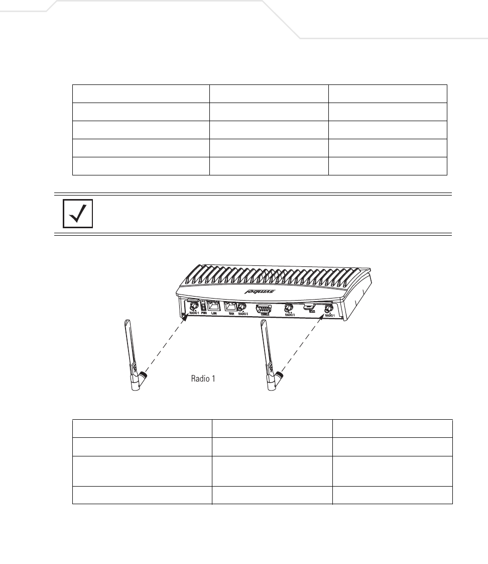
Hardware Installation 2-7
The AP-5131 2.4 GHz antenna suite includes the following models:
The AP-5131 5.2 GHz antenna suite includes the following models:
Symbol Part Number Antenna Type Nominal Net Gain (dBi)
ML-2499-11PNA2-01R Wide Angle Directional 8.5
ML-2499-HPA3-01R Omni-Directional Antenna 3.3
ML-2499-BYGA2-01R Yagi Antenna 13.9
ML-2452-APA2-01 Dual-Band 3.0
NOTE An additional adapter is required to use ML-2499-11PNA2-01 and
ML-2499-BYGA2-01 model antennae. Please contact Symbol for more
information.
Symbol Part Number Antenna Type Nominal Net Gain (dBi)
ML-5299-WPNA1-01R Panel Antenna 13.0
ML-5299-HPA1-01R Wide-Band Omni-Directional
Antenna
5.0
ML-2452-APA2-0 Dual-Band 4.0
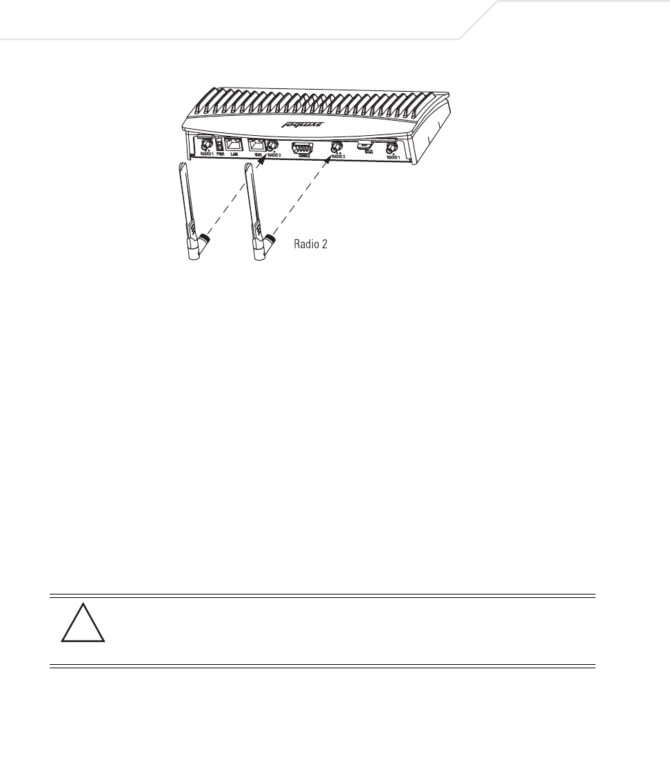
AP-51xx Access Point Product Reference Guide
2-8
For detailed specifications on the 2.4 GHz and 5.2 GHz antennae mentioned in this section, see
section 2.4 GHz Antenna Matrix on page A-5 and section 5.2 GHz Antenna Matrix on page A-5.
2.4.2.2 AP-5181 Antenna Options -TBD
2.5 Power Options
2.5.1 AP-5131 Power Options
The power options for the AP-5131 include:
• Symbol Power Injector (Part No. AP-PSBIAS-1P2-AFR)
• Symbol 48-Volt Power Supply (Part No. 50-24000-050)
• Any standard 802.3af compliant device.
2.5.2 AP-5181 Power Options
The power options for the AP-5181 include:
• Symbol Power Injector (Part No. AP-PSBIAS-1P2-AFR)
• Symbol (AP-5181 specific) 48-Volt Power Supply (Part No. AP-PSBIAS-5181-01R)
• Any standard 802.3af compliant device.
CAUTION An AP-5181 model access point cannot use the AP-5131
recommended Symbol 48-Volt Power Supply (Part No. 50-24000-050).
However, Symbol does recommend the AP-PSBIAS-5181-01R model
power supply for use the AP-5181.
!

Hardware Installation 2-9
2.6 Symbol Power Injector System
The access point can receive power either directly form a Symbol 48V AC-DC power supply
or via an Ethernet cable connected to the LAN port (using the 802.3af standard).
When users purchase a Symbol WLAN solution, they often need to place access points in obscure
locations. In the past, a dedicated power source was required for each access point in addition to the
Ethernet infrastructure. This often required an electrical contractor to install power drops at each
access point location. An approved power injector solution merges power and Ethernet into one
cable, reducing the burden of installation and allows optimal access point placement in respect to
the intended radio coverage area.
The Symbol Power Injector is included in certain AP-5131 and AP-5181 kits. The Symbol Power
Injector (Part No. AP-PSBIAS-1P2-AFR) is an integrated AC-DC converter and 802.3af power injector
which requires 110-220V AC power to combine low-voltage DC with Ethernet data in a single cable
connecting to the access point. The access point can only use a Power Injector when connected to
the LAN port.
The Symbol AP-5131 and AP-5181 Power Supply (Part Numbers 50-24000-050 and
AP-PSBIAS-5181-01R respectively) are not included in the kit and must be orderable separately as
an accessory.
A separate power injector is required for each access point comprising the network.
2.6.1 Installing the Power Injector
Refer to the following sections for information on planning, installing, and validating the power
injector installation:
•Preparing for Site Installation
•Cabling the Power Injector
•Power Injector LED Indicators
CAUTION The access point supports any standards-based 802.3af compliant
power source (including non-Symbol power sources). However, using
the wrong solution (including a POE system used on a legacy Symbol
access point) could severely damage the access point and void the
product warranty.
!

AP-51xx Access Point Product Reference Guide
2-10
2.6.1.1 Preparing for Site Installation
The power injector can be installed free standing, on an even horizontal surface or wall mounted
using the power injector’s wall mounting key holes. The following guidelines should be adhered to
before cabling the power injector to an Ethernet source and an access point:
• Do not block or cover airflow to the power injector.
• Keep the power injector away from excessive heat, humidity, vibration and dust.
• The power injector is not a repeater, and does not amplify the Ethernet data signal. For
optimal performance, ensure the power injector is placed as close as possible to the
network data port.
2.6.1.2 Cabling the Power Injector
To install the power injector to an Ethernet data source and access point:
1. Connect the power injector to an AC outlet (110VAC to 220VAC).
2. Connect an RJ-45 Ethernet cable between the network data supply (host) and the power
injector Data In connector.
3. Connect an RJ-45 Ethernet cable between the power injector Data & Power Out connector
and the Symbol access point LAN port.
Ensure the cable length from the Ethernet source (host) to the power injector and access
point does not exceed 100 meters (333 ft.)
CAUTION Ensure AC power is supplied to the power injector using an AC cable
with an appropriate ground connection approved for the country of
operation.
CAUTION Cabling the power injector to the access point’s WAN port renders the
AP-5131 non-operational. Only use a AP-PSBIAS-1P2-AFR model
power injector with the access point’s LAN port.
!
!
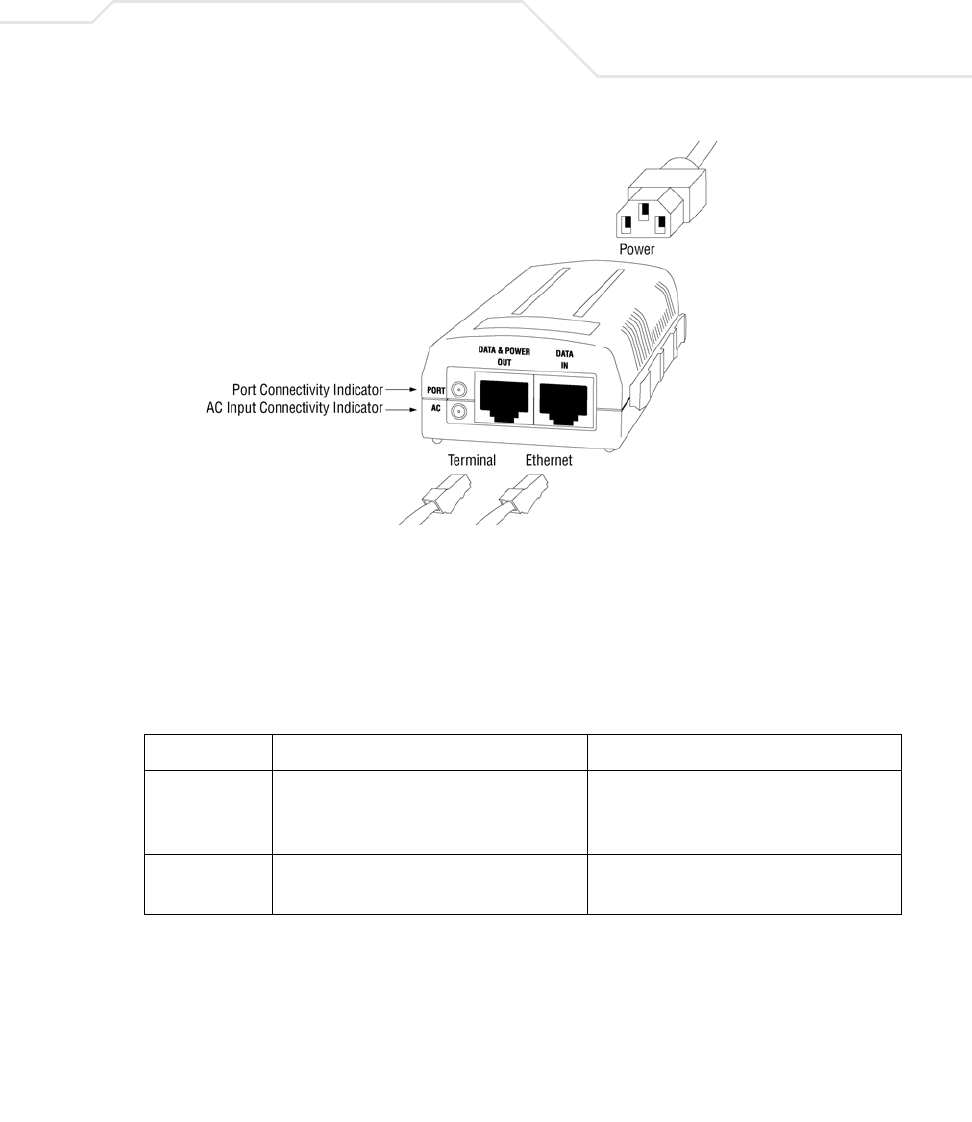
Hardware Installation 2-11
The power injector has no On/Off power switch. The power injector receives power and is
ready for access point device connection and operation as soon as AC power is applied.
2.6.1.3 Power Injector LED Indicators
The power injector demonstrates the following LED behavior under normal and/or problematic
operating conditions:
For more information and device specifications for the Symbol power injector, refer to the Power
Injector Quick Install Guide (Part No. 72-70762-01) available from the Symbol Web site.
LED AC (Main) Port
Green (Steady) Power injector is receiving power from AC
outlet.
Indicates a device is connected to the
power injector’s outgoing Data & Power
cable.
Green (Blinking) Output voltage source is out of range. The power injector is overloaded or has a
short circuit.

AP-51xx Access Point Product Reference Guide
2-12
2.7 Mounting the AP-5131
The AP-5131 can rest on a flat surface, attach to a wall, mount under a suspended T-Bar or above a
ceiling (plenum or attic). Choose one of the following mounting options based on the physical
environment of the coverage area. Do not mount the AP-5131 in a location that has not been approved
in a site survey.
Refer to the following, depending on how you intend to mount the AP-5131:
•Desk Mounted Installations
•Wall Mounted Installations
•Suspended Ceiling T-Bar Installations
•Above the Ceiling (Plenum) Installations
2.7.1 Desk Mounted Installations
The desk mount option uses rubber feet allowing the unit to sit on most flat surfaces. The four (4)
round rubber feet can be found in the AP-5131 (main) box in a separate plastic bag.
To install the AP-5131 in a desk mount orientation:
1. Turn the AP-5131 upside down.
2. Attach the radio antennae to their correct connectors.
The antenna protection plate cannot be used in a desk mount configuration, as the plate only
allows antennas to be positioned in a downward orientation.
3. Remove the backings from the four (4) rubber feet and attach them to the four rubber feet
recess areas on the AP-5131.
CAUTION Both the Dual and Single Radio model AP-5131’s use RSMA type
antenna connectors. On the Dual Radio AP-5131, a single dot on the
antenna connector indicates the primary antenna for both Radio 1 (2.4
GHz) and Radio 2 (5.2 GHz). Two dots designate the secondary
antenna for both Radio 1 and Radio 2. On Single Radio models, a
single dot on the antenna connector indicates the primary antenna for
Radio 1, and two dots designate the secondary antenna for Radio 1.
!
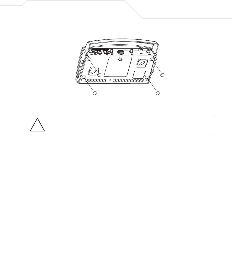
Hardware Installation 2-13
4. Cable the AP-5131 using either the Symbol power injector solution or an approved line cord
and power supply.
For Symbol power injector installations:
a. Connect a RJ-45 Ethernet cable between the network data supply (host) and the power
injector Data In connector.
b. Connect a RJ-45 Ethernet cable between the power injector Data & Power Out
connector and the Symbol AP-5131 LAN port.
c. Ensure the cable length from the Ethernet source (host) to the power injector and
AP-5131 does not exceed 100 meters (333 ft). The power injector has no On/Off power
switch. The power injector receives power as soon as AC power is applied. For more
information on using the power injector, see Symbol Power Injector System on page 2-9.
For standard Symbol 48-Volt power adapter (Part No. 50-24000-050) and line cord
installations:
a. Connect RJ-45 Ethernet cable between the network data supply (host) and the AP-5131
LAN port.
b. Verify the power adapter is correctly rated according the country of operation.
c. Connect the power supply line cord to the power adapter.
d. Attach the power adapter cable into the power connector on the AP-5131.
e. Plug the power adapter into an outlet.
CAUTION Do not supply power to the AP-5131 until the cabling of the unit is
complete.
!

AP-51xx Access Point Product Reference Guide
2-14
5. Verify the behavior of the AP-5131 LEDs. For more information, see AP-5131 LED Indicators
on page 2-21.
6. Return the AP-5131 to an upright position and place it in the location you wish it to operate.
Ensure the AP-5131 is sitting evenly on all four rubber feet.
The AP-5131 is ready to configure. For information on an AP-5131 default configuration, see
Getting Started on page 3-1. For specific details on AP-5131 system configurations, see
System Configuration on page 4-1.
2.7.2 Wall Mounted Installations
Wall mounting requires hanging the AP-5131 along its width (or length) using the pair of slots on the
bottom of the unit and using the AP-5131 itself as a mounting template for the screws. The AP-5131
can be mounted onto any plaster or wood wall surface.
The mounting hardware and tools (customer provided) required to install the AP-5131 on a wall
consists of:
• Two Phillips pan head self-tapping screws (ANSI Standard) #6-18 X 0.875in. Type A or AB
Self-Tapping screw, or (ANSI Standard Metric) M3.5 X 0.6 X 20mm Type D Self-Tapping
screw
• Two wall anchors
• Security cable (optional)
To mount the AP-5131 on a wall:
1. Orient the AP-5131 on the wall by its width or length.
2. Using the arrows on one edge of the case as guides, move the edge to the midline of the
mounting area and mark points on the midline for the screws.
3. At each point, drill a hole in the wall, insert an anchor, screw into the anchor the wall
mounting screw and stop when there is 1mm between the screw head and the wall.
If pre-drilling a hole, the recommended hole size is 2.8mm (0.11in.) if the screws are going
directly into the wall and 6mm (0.23in.) if wall anchors are being used.
4. If required, install and attach a security cable to the AP-5131 lock port.
5. Place the large corner of each of the mount slots over the screw heads.
6. Slide the AP-5131 down along the mounting surface to hang the mount slots on the screw
heads.
7. Attach the radio antennae to their correct connectors.
Hardware Installation 2-15
8. Cable the AP-5131 using either the Symbol power injector solution or an approved line cord
and power supply.
For Symbol power injector installations:
a. Connect a RJ-45 Ethernet cable between the network data supply (host) and the Power
Injector Data In connector.
b. Connect a RJ-45 Ethernet cable between the power injector Data & Power Out
connector and the AP-5131 LAN port.
c. Ensure the cable length from the Ethernet source (host) to the power injector and
AP-5131 does not exceed 100 meters (333 ft). The power injector has no On/Off power
switch. The power injector receives power as soon as AC power is applied. For more
information on using the power injector, see Symbol Power Injector System on page 2-9.
For standard Symbol 48-Volt Power Adapter (Part No. 50-24000-050) and line cord
installations:
a. Connect RJ-45 Ethernet cable between the network data supply (host) and the AP-5131
LAN port.
b. Verify the power adapter is correctly rated according the country of operation.
c. Connect the power supply line cord to the power adapter.
d. Attach the power adapter cable into the power connector on the AP-5131.
CAUTION Both the Dual and Single Radio model AP-5131s use RSMA type
antenna connectors. On the Dual Radio AP-5131, a single dot on the
antenna connector indicates the primary antenna for both Radio 1 (2.4
GHz) and Radio 2 (5.2 GHz). Two dots designate the secondary
antenna for both Radio 1 and Radio 2. On Single Radio models, a
single dot on the antenna connector indicates the primary antenna for
Radio 1, and two dots designate the secondary antenna for Radio 1.
NOTE The access point must be mounted with the RJ45 cable connector
oriented upwards to ensure proper operation.
CAUTION Do not supply power to the AP-5131 until the cabling of the unit is
complete.
!
!
AP-51xx Access Point Product Reference Guide
2-16
e. Plug the power adapter into an outlet.
9. Verify the behavior of the AP-5131 LEDs. For more information, see AP-5131 LED Indicators
on page 2-21.
The AP-5131 is ready to configure. For information on an AP-5131 default configuration, see
Getting Started on page 3-1. For specific details on AP-5131 system configurations, see
System Configuration on page 4-1.
2.7.3 Suspended Ceiling T-Bar Installations
A suspended ceiling mount requires holding the AP-5131 up against the T-bar of a suspended ceiling
grid and twisting the AP-5131 chassis onto the T-bar.
The mounting hardware and tools (customer provided) required to install the AP-5131 on a ceiling T-
bar consists of:
• Safety wire (recommended)
• Security cable (optional)
To install the AP-5131 on a ceiling T-bar:
1. If required, loop a safety wire —with a diameter of at least 1.01 mm (.04 in.), but no more
than 0.158 mm (.0625 in.) —through the tie post (above the AP-5131’s console connector)
and secure the loop.
2. If required, install and attach a security cable to the AP-5131 lock port.
3. Attach the radio antennae to their correct connectors.
NOTE If the AP-5131 is utilizing remote management antennae, a wire cover
can be used to provide a clean finished look to the installation. Contact
Symbol for more information.
CAUTION Both the Dual and Single Radio model AP-5131s use RSMA type
antenna connectors. On the Dual Radio AP-5131, a single dot on the
antenna connector indicates the primary antenna for both Radio 1 (2.4
GHz) and Radio 2 (5.2 GHz). Two dots designate the secondary
antenna for both Radio 1 and Radio 2. On Single Radio models, a
single dot on the antenna connector indicates the primary antenna for
Radio 1, and two dots designate the secondary antenna for Radio 1
!

Hardware Installation 2-17
4. Cable the AP-5131 using either the Symbol power injector solution or an approved line cord
and power supply.
For Symbol power injector installations:
a. Connect a RJ-45 Ethernet cable between the network data supply (host) and the Power
Injector Data In connector.
b. Connect a RJ-45 Ethernet cable between the power injector Data & Power Out
connector and the AP-5131 LAN port.
c. Ensure the cable length from the Ethernet source (host) to the power injector and
AP-5131 does not exceed 100 meters (333 ft). The power injector has no On/Off power
switch. The power injector receives power as soon as AC power is applied. For more
information on using the power injector, see Symbol Power Injector System on page 2-9.
For standard Symbol 48-Volt Power Adapter (Part No. 50-24000-050) and line cord
installations:
a. Connect RJ-45 Ethernet cable between the network data supply (host) and the AP-5131
LAN port.
b. Verify the power adapter is correctly rated according the country of operation.
c. Connect the power supply line cord to the power adapter.
d. Attach the power adapter cable into the power connector on the AP-5131.
e. Plug the power adapter into an outlet.
5. Verify the behavior of the AP-5131 LEDs. For more information, see AP-5131 LED Indicators
on page 2-21.
6. Align the bottom of the ceiling T-bar with the back of the AP-5131.
7. Orient the AP-5131 chassis by its length and the length of the ceiling T-bar.
8. Rotate the AP-5131 chassis 45 degrees clockwise, or about 10 o’clock.
9. Push the back of the AP-5131 chassis on to the bottom of the ceiling T-bar.
CAUTION Do not supply power to the AP-5131 until the cabling of the unit is
complete.
CAUTION Ensure the safety wire and cabling used in the T-Bar AP-5131
installation is securely fastened to the building structure in order to
provide a safe operating environment.
!
!
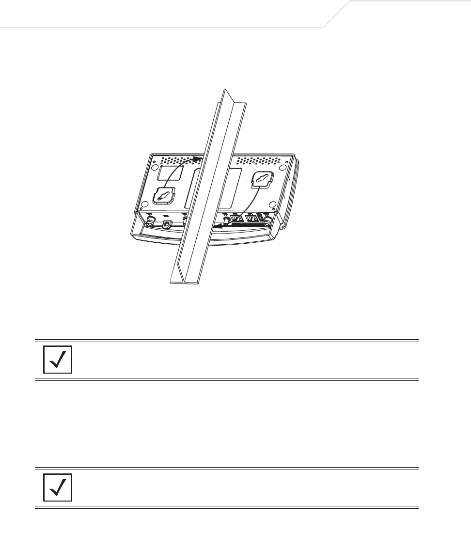
AP-51xx Access Point Product Reference Guide
2-18
10. Rotate the AP-5131 chassis 45 degrees counter-clockwise. The clips click as they fasten to
the T-bar.
11. The AP-5131 is ready to configure. For information on an AP-5131 default configuration, see
Getting Started on page 3-1. For specific details on AP-5131 system configurations, see
System Configuration on page 4-1.
2.7.4 Above the Ceiling (Plenum) Installations
An AP-5131 above the ceiling installation requires placing the AP-5131 above a suspended ceiling
and installing the provided light pipe under the ceiling tile for viewing the rear panel status LEDs of
the unit. An above the ceiling AP-5131 installation enables installations compliant with drop ceilings,
suspended ceilings and industry standard tiles from .625 to .75 inches thick.
NOTE If the AP-5131 is utilizing remote management antennae, a wire cover
can be used to provide a clean finished look to the installation. Contact
Symbol for more information.
NOTE The AP-5131 is Plenum rated to UL2043 and NEC1999 to support above
the ceiling installations.

Hardware Installation 2-19
The mounting hardware required to install the AP-5131 above a ceiling consists of:
• Light pipe
• Badge for light pipe
• Decal for badge
• Safety wire (strongly recommended)
• Security cable (optional)
To install the AP-5131 above a ceiling:
1. If possible, remove the adjacent ceiling tile from its frame and place it aside.
2. Install a safety wire, between 1.5mm (.06in.) and 2.5mm (.10in.) in diameter, in the ceiling
space.
3. If required, install and attach a security cable to the AP-5131’s lock port.
4. Mark a point on the finished side of the tile where the light pipe is to be located.
5. Create a light pipe path hole in the target position on the ceiling tile.
6. Use a drill to make a hole in the tile the approximate size of the AP-5131 LED light pipe.
7. Remove the light pipe’s rubber stopper before installing the light pipe.
8. Connect the light pipe to the bottom of the AP-5131. Align the tabs and rotate approximately
90 degrees. Do not over tighten
CAUTION Symbol does not recommend mounting the AP-5131 directly to any
suspended ceiling tile with a thickness less than 12.7mm (0.5in.) or a
suspended ceiling tile with an unsupported span greater than 660mm
(26in.). Symbol strongly recommends fitting the AP-5131 with a safety
wire suitable for supporting the weight of the device. The safety wire
should be a standard ceiling suspension cable or equivalent steel wire
between 1.59mm (.062in.) and 2.5mm (.10in.) in diameter.
CAUTION Symbol recommends care be taken not to damage the finished surface
of the ceiling tile when creating the light pipe hole and installing the
light pipe.
!
!
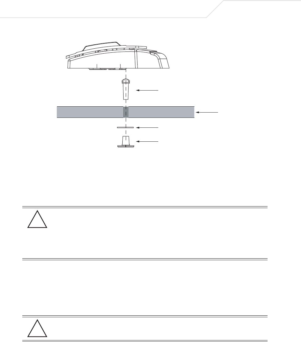
AP-51xx Access Point Product Reference Guide
2-20
9. Snap the clips of the light pipe into the bottom of the AP-5131.
10. Fit the light pipe into hole in the tile from its unfinished side.
11. Place the decal on the back of the badge and slide the badge onto the light pipe from the
finished side of the tile.
12. Attach the radio antennae to their correct connectors.
13. Attach safety wire (if used) to the AP-5131 safety wire tie point or security cable (if used) to
the AP-5131’s lock port.
14. Align the ceiling tile into its former ceiling space.
15. Cable the AP-5131 using either the Symbol power injector solution or an approved line cord
and power supply.
CAUTION Both the Dual and Single Radio model AP-5131s use RSMA type
antenna connectors. On the Dual Radio AP-5131, a single dot on the
antenna connector indicates the primary antenna for both Radio 1 (2.4
GHz) and Radio 2 (5.2 GHz). Two dots designate the secondary
antenna for both Radio 1 and Radio 2. On Single Radio models, a
single dot on the antenna connector indicates the primary antenna for
Radio 1, and two dots designate the secondary antenna for Radio 1.
CAUTION Do not supply power to the AP-5131 until the cabling of the unit is
complete.
Light Pipe
Decal
Badge
Ceiling Tile
!
!

Hardware Installation 2-21
For Symbol power injector installations:
a. Connect a RJ-45 Ethernet cable between the network data supply (host) and the Power
Injector Data In connector.
b. Connect a RJ-45 Ethernet cable between the power injector Data & Power Out
connector and the AP-5131 LAN port.
c. Ensure the cable length from the Ethernet source (host) to the power injector and
AP-5131 does not exceed 100 meters (333 ft). The power injector has no On/Off power
switch. The power injector receives power as soon as AC power is applied. For more
information on using the power injector, see Symbol Power Injector System on page 2-9.
For standard Symbol 48-Volt Power Adapter (Part No. 50-24000-050) and line cord
installations:
a. Connect RJ-45 Ethernet cable between the network data supply (host) and the AP-5131
LAN port.
b. Verify the power adapter is correctly rated according the country of operation.
c. Connect the power supply line cord to the power adapter.
d. Attach the power adapter cable into the power connector on the AP-5131.
e. Plug the power adapter into an outlet.
16. Verify the behavior of the AP-5131 LED lightpipe. For more information, see AP-5131 LED
Indicators on page 2-21.
17. Place the ceiling tile back in its frame and verify it is secure.
The AP-5131 is ready to configure. For information on an AP-5131 default configuration, see
Getting Started on page 3-1. For specific details on AP-5131 system configurations, see
System Configuration on page 4-1.
2.8 AP-5131 LED Indicators
The AP-5131 utilizes seven LED indicators. Five LEDs display within four LED slots on the front of the
AP-5131 (on top of the AP-5131 housing) and two LEDs (for above the ceiling installations) are located
on the back of the device (the side containing the LAN, WAN and antenna connectors).
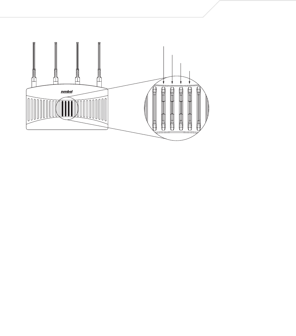
AP-51xx Access Point Product Reference Guide
2-22
The five LEDs on the top housing of the AP-5131 are clearly visible in table-top, wall and below ceiling
installations. The five AP-5131 top housing LEDs have the following display and functionality:
The LEDs on the rear of the AP-5131 are viewed using a single (customer installed) extended
lightpipe, adjusted as required to suit above the ceiling installations. The LEDs displayed using the
lightpipe have the following color display and functionality:
Power Status Solid white indicates the AP-5131 is adequately powered.
Error Conditions
Solid red indicates the AP-5131 is experiencing a problem condition requiring
immediate attention.
Ethernet Activity Flashing white indicates data transfers and Ethernet activity.
802.11a Radio Activity
Flickering amber indicates beacons and data transfers over the AP-5131
802.11a radio.
802.11b/g Radio
Activity
Flickering green indicates beacons and data transfers over the AP-5131
802.11b/g radio.
Data Over Ethernet
802.11a Radio Activity
802.11b/g Radio Activity
Power and Error Conditions (Split LE
D)

Hardware Installation 2-23
2.9 Mounting the AP-5181
The AP-5181 can be connected to a pole or attach to a wall. Choose one of the following mounting
options based on the physical environment of the coverage area. Do not mount the AP-5181 in a
location that has not been approved in a site survey.
Refer to the following, depending on how you intend to mount the AP-5181:
•AP-5181 Pole Mounted Installations
•AP-5181 Wall Monuted Installations
2.9.1 AP-5181 Pole Mounted Installations
Complete the following steps to mount the AP-5181 to a 1.5 to 2 inch diameter steel pole or tube
(using the mounting bracket):
1. Fit the edges of the V-shaped clamp parts into the slots on the flat side of the rectangular
plate. The inner slots are for the 1.5-inch diameter pole and the outer slots for a 2-inch
diameter pole.
2. Place the V-shaped bracket clamp parts around the pole and tighten the nuts just enough to
hold the bracket to the pole. (The bracket may need to be rotated around the pole during the
antenna alignment process).
3. Attach the square mounting plate to the bridge with the supplied screws.
4. Attach the AP-5181 and mounting plate to the bracket already fixed to the pole.
5. Secure the AP-5181 to the pole bracket using the provided nuts.
Boot and Power Status Solid white indicates the AP-5131 is adequately powered.
Error Conditions
Solid red indicates the AP-5131 is experiencing a problem condition requiring
immediate attention.
Power and Error
Conditions
Blinking red indicates the AP-5131 Rogue AP Detection feature has located a
rogue device
AP-51xx Access Point Product Reference Guide
2-24
2.9.2 AP-5181 Wall Monuted Installations
Complete the following steps to mount the AP-5181 to a wall using the supplied wall-mounting
bracket:
1. Attach the bracket to a wall with flat side flush against the wall (see the illustration below).
Position the bracket in the intended location and mark the positions of the four mounting
screw holes.
2. Drill four holes in the wall that match the screws and wall plugs.
3. Secure the bracket to the wall.
4. Attach the square mounting plate to the bridge with the supplied screws. Attach the bridge
to the plate on the pole.
5. Use the included nuts to tightly secure the wireless bridge to the bracket.
NOTE The AP-5181 tilt angle may need to be adjusted during the antenna
alignment process. Verify the antenna polarization angle when installing,
enusre the antennas are oriented corretly in respect to the AP-5181's
coverage area.

Hardware Installation 2-25
2.10 AP-5181 LED Indicators
The AP-5181 utilizes four LED indicators. Five LEDs display within four LED slots on the back of the
access point. The five LEDs have the following display and functionality:
Illustration forthcoming
The LEDs on the rear of the access point are viewed using a single (customer installed) extended
lightpipe, adjusted as required to suit above the ceiling installations.
Power Status Solid white indicates the AP-5131 is adequately powered.
Error Conditions
Solid red indicates the AP-5131 is experiencing a problem condition requiring
immediate attention.
Ethernet Activity Flashing white indicates data transfers and Ethernet activity.
802.11a Radio Activity
Flickering amber indicates beacons and data transfers over the AP-5131
802.11a radio.
802.11b/g Radio
Activity
Flickering green indicates beacons and data transfers over the AP-5131
802.11b/g radio.

AP-51xx Access Point Product Reference Guide
2-26
2.11 Setting Up MUs
For a discussion of how to initially test the access point to ensure it can interoperate with the MUs
intended for its operational environment, see Basic Device Configuration on page 3-3 and specifically
Testing Connectivity on page 3-11.
Refer to the LA-5030 & LA-5033 Wireless Networker PC Card and PCI Adapter Users Guide, available
from the Symbol Web site, for installing drivers and client software if operating in an 802.11a/g
network environment.
Refer to the Spectrum24 LA-4121 PC Card, LA-4123 PCI Adapter & LA-4137 Wireless Networker User
Guide, available from the Symbol Web site, for installing drivers and client software if operating in
an 802.11b network environment.
Use the default values for the ESSID and other configuration parameters until the network connection
is verified. MUs attach to the network and interact with the AP transparently.

Getting Started
The access point should be installed in an area tested for radio coverage using one of the site survey
tools available to the Symbol field service technician. Once an installation site has been identified,
the installer should carefully follow the hardware precautions, requirements, mounting guidelines
and power options outlined in Appendix 2, Hardware Installation on page 2-1.
See the following sections for more details:
•Installing the Access Point
•Configuration Options
•Basic Device Configuration
3.1 Installing the Access Point
Make the required cable and power connections before mounting the access point in its final
operating position. Test the access point with an associated MU before mounting and securing the
access point. Carefully follow the mounting instructions in one of the following sections to ensure the
access point is installed correctly:

AP-51xx Access Point Product Reference Guide
3-2
For installing an AP-5131 model access point
• For instructions on installing the AP-5131 on a table top, see Desk Mounted Installations on
page 2-12.
• For instructions on mounting an AP-5131 to a wall, see Wall Mounted Installations on page
2-14.
• For instructions on mounting an AP-5131 to a ceiling T-bar, see Suspended Ceiling T-Bar
Installations on page 2-16.
• For instructions on installing the AP-5131 in an above the ceiling attic space, see
Above the Ceiling (Plenum) Installations on page 2-18.
For installing an AP-5181 model access point:
• For instructions on installing the AP-5181 to a pole, see AP-5181 Pole Mounted Installations
on page 2-23.
• For instructions on installing the AP-5181 to a wall, see AP-5181 Wall Monuted Installations
on page 2-24.
For information on the 802.11a and 802.11b/g radio antenna suite available to the access point, see
Antenna Options on page 2-6. For more information on using a Symbol Power Injector to combine
Ethernet and power in one cable to the access point, see Symbol Power Injector System on page 2-
9. To verify AP-5131 LED behavior once installed, see AP-5131 LED Indicators on page 2-21. To verify
the behavior of the AP-5181 LEDs once installed, see AP-5181 LED Indicators on page 2-25.
3.2 Configuration Options
Once installed and powered, the access point can be configured using one of several connection
techniques. Managing the access point includes viewing network statistics and setting configuration
options. The access point requires one of the following connection methods to manage the network:
•Secure Java-Based WEB UI - (use Sun Microsystems’ JRE 1.5 or higher available from Sun’s
Web site. Disable Microsoft’s Java Virtual Machine if installed). For information on using the
Web UI to set access point default configuration values, see Basic Device Configuration on
page 3-3 or chapters 4 through 7 of this guide.
•Command Line Interface (CLI) via Serial, Telnet and SSH. The access point CLI is accessed
through the RS232 port, via Telnet or SSH. The CLI follows the same configuration
conventions as the device user interface with a few documented exceptions. For details on
using the CLI to manage the access point, see Appendix 8, Command Line Interface
Reference on page 8-1.
Getting Started 3-3
•Config file - Readable text file; Importable/Exportable via FTP, TFTP and HTTP. Configuration
settings for an access point can be downloaded from the current configuration of another
access point meeting the import/export requirements. For information on importing or
exporting configuration files, see Importing/Exporting Configurations on page 4-36.
•MIB (Management Information Base) accessing the access point SNMP functions using a
MIB Browser. The access point download package contains the following 2 MIB files:
• Symbol-CC-WS2000-MIB-2.0 (standard Symbol MIB file)
• Symbol-AP-5131-MIB (AP-5131 specific MIB file)
3.3 Basic Device Configuration
For the basic setup described in this section, the Java-based Web UI will be used to configure the
access point. Use the access point’s LAN interface for establishing a link with the access point.
Configure the access point as a DHCP client. For optimal screen resolution, set your screen resolution
to 1024 x 768 pixels or greater.
1. Start Internet Explorer and enter the following IP address in the address field: 192.168.0.1.
The access point login screen displays.
NOTE DNS names are not supported as a valid IP address for the access point.
The user is required to enter a numerical IP address.
NOTE For optimum compatibility, use Sun Microsystems’ JRE 1.5 or higher
(available from Sun’s Website), and be sure to disable Microsoft’s Java
Virtual Machine if installed.
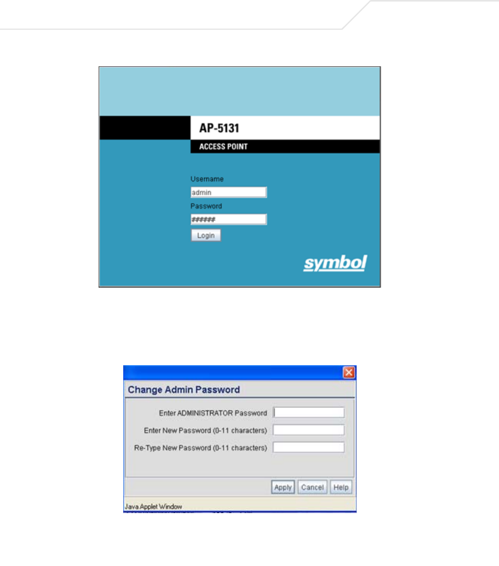
AP-51xx Access Point Product Reference Guide
3-4
2. Log in using admin as the default User ID and symbol as the default Password. Though the
example above is for an AP-5131, there is no difference for an AP-5181.
3. If the default login is successful, the Change Admin Password window displays. Change
the password.
Enter the current password and a new admin password in fields provided, and click Apply.
Once the admin password has been updated, a warning message displays stating the access
point must be set to a country.
Getting Started 3-5
The export function will always export the encrypted Admin User password. The import
function will import the Admin Password only if the access point is set to factory default. If
the access point is not configured to factory default settings, the Admin User password WILL
NOT get imported.
.
3.3.1 Configuring Device Settings
Configure a set of minimum required device settings within the Quick Setup screen. The values
defined within the Quick Setup screen are also configurable in numerous other locations within the
menu tree. When you change the settings in the Quick Setup screen, the values also change within
the screen where these parameters also exist. Additionally, if the values are updated in these other
screens, the values initially set within the Quick Setup screen will be updated.
To define a basic access point configuration:
1. Select System Configuration -> Quick Setup from the menu tree, if the Quick Setup
screen is not already displayed.
2. Enter a System Name for the access point.
The System Name is useful if multiple Symbol devices are being administered.
3. Select the Country for the access point’s country of operation from the drop-down menu
The access point prompts the user for the correct country code on the first login. A warning
message also displays stating that an incorrect country settings may result in illegal radio
operation. Selecting the correct country is central to legally operating the access point. Each
country has its own regulatory restrictions concerning electromagnetic emissions and the
maximum RF signal strength that can be transmitted. To ensure compliance with national
and local laws, be sure to set the Country accurately. CLI and MIB users cannot configure
their access point until a two character country code (for example, United States - us) is set.
Refer to Appendix A, Country Codes on page A-7 for the two character country codes.
NOTE Though the access point can have its basic settings defined using a
number of different screens, Symbol recommends using the access point
Quick Setup screen to set the correct country of operation and define its
minimum required configuration from one convenient location.
NOTE The System Name and Country are also configurable within the System
Settings screen. Refer to Configuring System Settings on page 4-2 (if
necessary) to set a system location and admin email address for the
access point or to view other default settings.
AP-51xx Access Point Product Reference Guide
3-6
4. Optionally enter the IP address of the server used to provide system time to the access point
within the Time Server field.
Once the IP address is entered, the access point’s Network Time Protocol (NTP) functionality
is engaged automatically. Refer to the access point Product Reference Guide for information
on defining alternate time servers and setting a synchronization interval for the access point
to adjust its displayed time. Refer to Configuring Network Time Protocol (NTP) on page 4-31
(if necessary) for information on setting alternate time servers and setting a synchronization
interval for the access point to adjust its displayed time.
5. Click the WAN tab to set a minimum set of parameters for using the WAN interface.
a. Select the Enable WAN Interface checkbox to enable a connection between the
access point and a larger network or outside world through the WAN port. Disable this
option to effectively isolate the access point’s WAN connection. No connections to a
larger network or the Internet will be possible. MUs cannot communicate beyond the
configured subnets.
b. Select the This Interface is a DHCP Client checkbox to enable DHCP for the access
point WAN connection. This is useful, if the larger corporate network or Internet Service
Provider (ISP) uses DHCP. DHCP is a protocol that includes mechanisms for IP address
allocation and delivery of host-specific configuration parameters from a DHCP server to
a host. Some of these parameters are IP address, network mask, and gateway.
c. Specify an IP address for the access point’s WAN connection. An IP address uses a
series of four numbers expressed in dot notation, for example, 190.188.12.1 (no DNS
names supported).
d. Specify a Subnet Mask for the access point’s WAN connection. This number is
available from the ISP for a DSL or cable-modem connection, or from an administrator if
the access point connects to a larger network. A subnet mask uses a series of four
numbers expressed in dot notation. For example, 255.255.255.0 is a valid subnet mask.
NOTE DNS names are not supported as a valid IP address. The user is required
to enter a numerical IP address.
NOTE Symbol recommends that the WAN and LAN ports should not both be
configured as DHCP clients.

Getting Started 3-7
e. Define a Default Gateway address for the access point’s WAN connection. The ISP or
a network administrator provides this address.
f. Specify the address of a Primary DNS Server. The ISP or a network administrator
provides this address.
6. Optionally, use the Enable PPP over Ethernet checkbox to enable Point-to-Point over
Ethernet (PPPoE) for a high-speed connection that supports this protocol. Most DSL
providers are currently using or deploying this protocol. PPPoE is a data-link protocol for
dialup connections. PPPoE will allow the access point to use a broadband modem (DSL,
cable modem, etc.) for access to high-speed data networks.
a. Select the Keep Alive checkbox to enable occasional communications over the WAN
port even when client communications to the WAN are idle. Some ISPs terminate
inactive connections, while others do not. In either case, enabling Keep-Alive maintains
the WAN connection, even when there is no traffic. If the ISP drops the connection after
the idle time, the access point automatically reestablishes the connection to the ISP.
b. Specify a Username entered when connecting to the ISP. When the Internet session
begins, the ISP authenticates the username.
c. Specify a Password entered when connecting to the ISP. When the Internet session
starts, the ISP authenticates the password.
For additional access point WAN port configuration options, see Configuring WAN Settings
on page 5-14.
7. Click the LAN tab to set a minimum set of parameters to use the access point LAN interface.
a. Select the Enable LAN Interface checkbox to forward data traffic over the access point
LAN connection. The LAN connection is enabled by default.
b. Use the This Interface drop-down menu to specify how network address information
is defined over the access point’s LAN connection. Select DHCP Client if the larger
corporate network uses DHCP. DHCP is a protocol that includes mechanisms for IP
address allocation and delivery of host-specific configuration parameters from a DHCP
server to a host. Some of these parameters are IP address, network mask, and gateway.
Select DHCP Server to use the access point as a DHCP server over the LAN connection.
Select the Bootp client option to enable a diskless system to discover its own IP
address.
.
NOTE Symbol recommends that the WAN and LAN ports should not both be
configured as DHCP clients.
AP-51xx Access Point Product Reference Guide
3-8
c. If using the static or DHCP Server option, enter the network-assigned IP Address of the
access point.
d. The Subnet Mask defines the size of the subnet. The first two sets of numbers specify
the network domain, the next set specifies the subset of hosts within a larger network.
These values help divide a network into subnetworks and simplify routing and data
transmission.
e. If using the static or DHCP Server option, enter a Default Gateway to define the
numerical IP address of a router the access point uses on the Ethernet as its default
gateway.
f. If using the static or DHCP Server option, enter the Primary DNS Server numerical IP
address.
g. If using the DHCP Server option, use the Address Assignment Range parameter to
specify a range of IP address reserved for mapping clients to IP addresses. If a manually
(static) mapped IP address is within the IP address range specified, that IP address could
still be assigned to another client. To avoid this, ensure all statically mapped IP
addresses are outside of the IP address range assigned to the DHCP server.
For additional access point LAN port configuration options, see Configuring the LAN
Interface on page 5-1.
8. Enable the radio(s) using the Enable checkbox(es) within the Radio Configuration field. If
using a single radio access point, enable the radio, then select either 2.4 GHz or 5.2 GHz from
the RF Band of Operation field. Only one RF band option at a time is permissible in a
single-radio model. If using a dual-radio model, the user can enable both RF bands. For
additional radio configuration options, see Configuring the 802.11a or 802.11b/g Radio on
page 5-47.
9. Select the WLAN #1 tab (WLANs 1 - 4 are available within the Quick Setup screen) to define
its ESSID and security scheme for basic operation.
NOTE DNS names are not supported as a valid IP address for the access point.
The user is required to enter a numerical IP address.
NOTE A maximum of 16 WLANs are configurable within the Wireless
Configuration screen. The limitation of 16 WLANs exists regardless of
whether the access point is a single or dual-radio model.

Getting Started 3-9
a. Enter the Extended Services Set Identification (ESSID) and name associated with the
WLAN. For additional information on creating and editing up to 16 WLANs per access
point, see Creating/Editing Individual WLANs on page 5-24.
b. Use the Available On checkboxes to define whether the target WLAN is operating over
the 802.11a or 802.11b/g radio. Ensure the radio selected has been enabled (see step 8).
c. Even an access point configured with minimal values must protect its data against theft
and corruption. A security policy should be configured for WLAN1 as part of the basic
configuration outlined in this guide. A security policy can be configured for the WLAN
from within the Quick Setup screen. Policies can be defined over time and saved to be
used as needed as security requirements change. Symbol recommends you familiarize
yourself with the security options available on the access point before defining a
security policy. Refer to Configuring WLAN Security Settings on page 3-9.
10. Click Apply to save any changes to the access point Quick Setup screen. Navigating away
from the screen without clicking Apply results in all changes to the screens being lost.
11. Click Undo Changes (if necessary) to undo any changes made. Undo Changes reverts the
settings displayed on the access point Quick Setup screen to the last saved configuration.
3.3.1.1 Configuring WLAN Security Settings
To configure a basic security policy for a WLAN:
1. From the access point Quick Setup screen, click the Create button to the right of the Security
Policy item.
The New Security Policy screen displays with the Manually Pre-shared key/No
authentication and No Encryption options selected. Naming and saving such a policy (as
is) would provide no security and might only make sense in a guest network wherein no
sensitive data is either transmitted or received. Consequently, at a minimum, a basic
security scheme (in this case WEP 128) is recommended in a network environment wherein
sensitive data is transmitted.
2. Ensure the Name of the security policy entered suits the intended configuration or function
of the policy.
NOTE For information on configuring the other encryption and authentication
options available to the access point, see Configuring Security Options on
page 6-2.
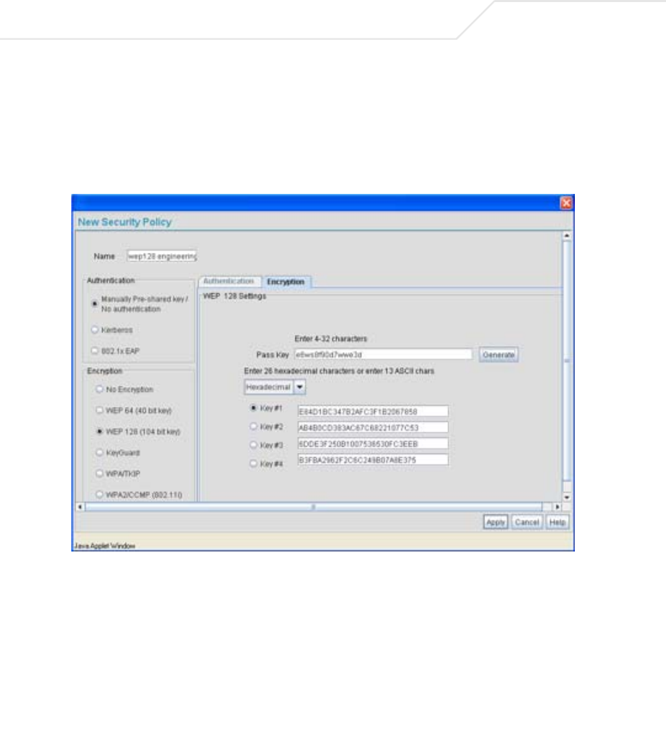
AP-51xx Access Point Product Reference Guide
3-10
Multiple WLANs can share the same security policy, so be careful not to name security
policies after specific WLANs or risk defining a WLAN to single policy. Symbol recommends
naming the policy after the attributes of the authentication or encryption type selected.
3. Select the WEP 128 (104 bit key) checkbox.
The WEP 128 Settings field displays within the New Security Policy screen.
4. Configure the WEP 128 Settings field as required to define the Pass Key used to generate
the WEP keys.
Pass Key Specify a 4 to 32 character pass key and click the Generate
button. The access point, other proprietary routers and Symbol
MUs use the same algorithm to convert an ASCII string to the
same hexadecimal number. Non-Symbol clients and devices
need to enter WEP keys manually as hexadecimal numbers. The
access point and its target client(s) must use the same pass key
to interoperate.
Getting Started 3-11
5. Click the Apply button to save the security policy and return to the access point Quick
Setup screen.
At this point, you can test the access point for MU interoperability.
3.3.2 Testing Connectivity
Verify the access point’s link with an MU by sending Wireless Network Management Protocol
(WNMP) ping packets to the associated MU. Use the Echo Test screen to specify a target MU and
configure the parameters of the test. The WNMP ping test only works with Symbol MUs. Only use a
Symbol MU to test access point connectivity using WNMP.
To ping a specific MU to assess its connection with an access point:
1. Select Status and Statistics -> MU Stats from the menu tree.
2. Select the Echo Test button from within the MU Stats Summary screen.
3. Define the following parameters for the test.
Keys #1-4 Use the Key #1-4 fields to specify key numbers. The key can be
either a hexidecimal or ASCII depending on which option is
selected from the drop-down menu. For WEP 64 (40-bit key), the
keys are 10 hexadecimal characters in length or 5 ASCII
characters. For WEP 128 (104-bit key), the keys are 26
hexadecimal characters in length or 13 ASCII characters. Select
one of these keys for activation by clicking its radio button. The
access point and its target client(s) must use the same key to
interoperate.
NOTE Before testing for connectivity, the target MU needs to be set to the same
ESSID as the access point. Since WEP 128 has been configured for the
access point, the MU also needs to be configured for WEP 128 and use
the same WEP keys. Ensure the MU is associated with the access point
before testing for connectivity.
Station Address The station address is the IP address of the target MU. Refer to
the MU Stats Summary screen for associated MU IP address
information.
Number of pings Defines the number of packets to be transmitted to the MU. The
default is 100.

AP-51xx Access Point Product Reference Guide
3-12
4. Click the Ping button to begin transmitting packets to the specified MU address.
Refer to the Number of Responses value to assess the number of responses from the MU
versus the number of ping packets transmitted by the access point. Use the ratio of packets
sent versus the number of packets received the link quality between the MU and the access
point.
Click the OK button to exit the Echo Test screen and return to the MU Stats Summary screen.
3.3.3 Where to Go from Here?
Once basic connectivity has been verified, the access point can be fully configured to meet the needs
of the network and the users it supports. Refer to the following:
• For detailed information on access point device access, SNMP settings, network time,
importing/exporting device configurations and device firmware updates, see Chapter 4,
System Configuration on page 4-1.
• For detailed information on configuring access point LAN interface (subnet) and WAN
interface see, Chapter 5, Network Management on page 5-1.
• For detailed information on configuring specific encryption and authentication security
schemes for individual access point WLANs, see Chapter 6, Configuring Access Point
Security on page 6-1.
• To view detailed statistics on the access point and its associated MUs, see Chapter 7,
Monitoring Statistics on page 7-1.
Packet Length Specifies the length of each packet transmitted to the MU during
the test. The default length is 100 bytes.

System Configuration
The Symbol access point contains a built-in browser interface for system configuration and remote
management using a standard Web browser such as Microsoft Internet Explorer, Netscape Navigator
or Mozilla Firefox. The browser interface also allows for system monitoring of the access point.
Web management of the access point requires either Microsoft Internet Explorer 5.0 or later or
Netscape Navigator 6.0 or later.
To connect to the AP, the access point IP is required. Enter 192.168.0.1 for the default IP address. The
password is “symbol.”
.
NOTE For optimum compatibility, use Sun Microsystems’ JRE 1.5 or higher
(available from Sun’s Web site), and be sure to disable Microsoft’s Java
Virtual Machine if installed.
NOTE DNS names are not supported as a valid IP address for the access point.
The user is required to enter a numerical IP address.
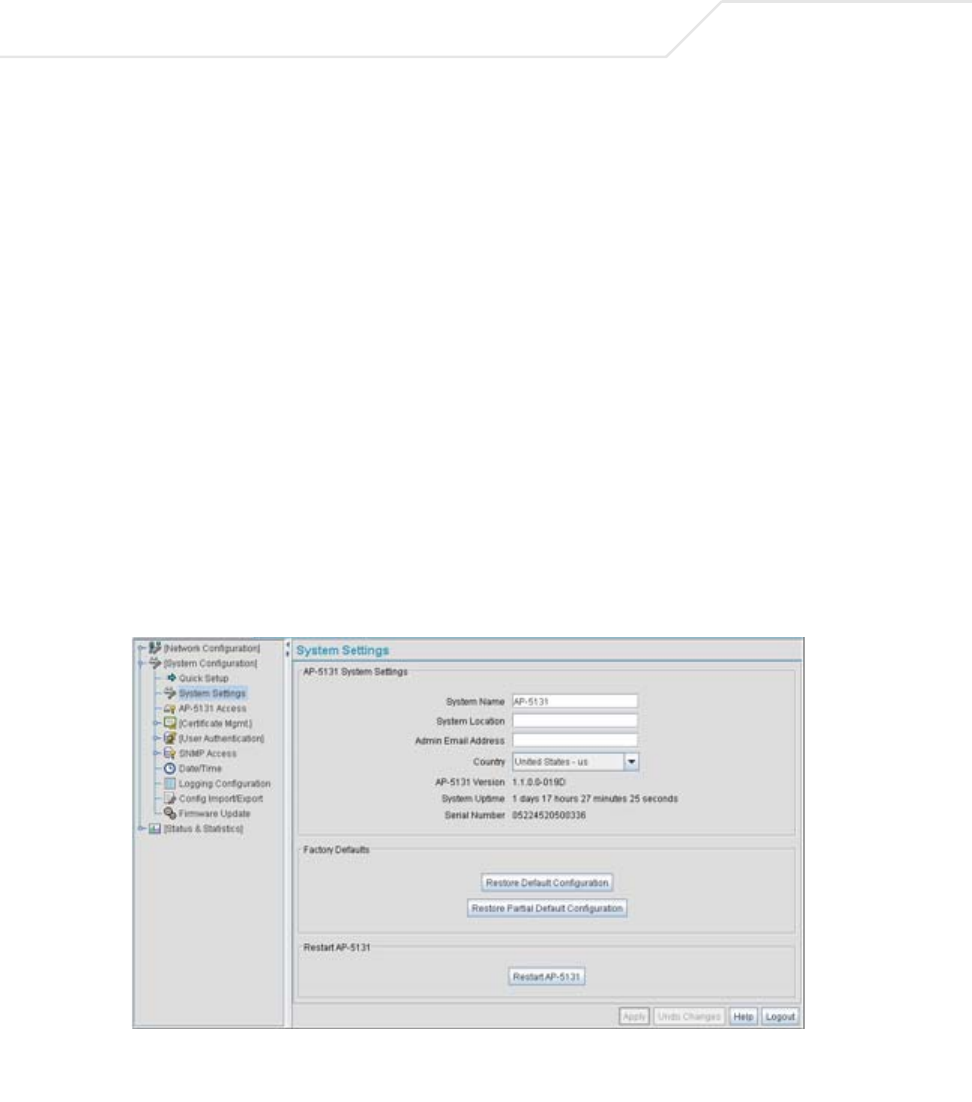
AP-51xx Access Point Product Reference Guide
4-2
System configuration topics include:
•Configuring System Settings
•Configuring Data Access
•Managing Certificate Authority (CA) Certificates
•Configuring SNMP Settings
•Configuring Network Time Protocol (NTP)
•Logging Configuration
•Importing/Exporting Configurations
•Updating Device Firmware
4.1 Configuring System Settings
Use the System Settings screen to specify the name and location of the access point, assign an
email address for the network administrator, restore the AP’s default configuration or restart the AP.
To configure System Settings for the access point:
1. Select System Configuration -> System Settings from the access point menu tree.
2. Configure the access point System Settings field to assign a system name and location,
set the country of operation and view device version information.

System Configuration 4-3
System Name Specify a device name for the access point. Symbol recommends
selecting a name serving as a reminder of the user base the access
point supports (engineering, retail, etc.).
System Location Enter the location of the access point. The System Location
parameter acts as a reminder of where the AP can be found. Use
the System Name field as a specific identifier of device location.
Use the System Name and System Location fields together to
optionally define the AP name by the radio coverage it supports and
specific physical location. For example, “second floor engineering”
Admin Email Address Specify the AP administrator's email address.
Country The access point prompts the user for the correct country code
after the first login. A warning message also displays stating that
an incorrect country setting will lead to an illegal use of the access
point. Use the pull-down menu to select the country of operation.
Selecting the correct country is extremely important. Each country
has its own regulatory restrictions concerning electromagnetic
emissions (channel range) and the maximum RF signal strength
transmitted. To ensure compliance with national and local laws, be
sure to set the Country field correctly.
If using the access point configuration file, CLI or MIB to configure
the access point’s country code, see Country Codes on page A-7.
access point Version The displayed number is the current version of the access point
device firmware. Use this information to determine if the AP is
running the most recent firmware available from Symbol. Use the
Firmware Update screen to keep the AP’s firmware up to date.
For more information, see Updating Device Firmware on page 4-40.
System Uptime Displays the current uptime of the access point defined in the
System Name field. System Uptime is the cumulative time since
the access point was last rebooted or lost power.
Serial Number Displays the access point Media Access Control (MAC) address.
The access point MAC address is hard coded at the factory and
cannot be modified. The LAN and WAN port MAC addresses can be
located within the LAN and WAN Stats screens. For information on
locating the access point MAC addresses, see Viewing WAN
Statistics on page 7-2 and Viewing LAN Statistics on page 7-6.

AP-51xx Access Point Product Reference Guide
4-4
3. Refer to the Factory Defaults field to restore either a full or partial default configuration.
4. Use the Restart access point field to restart the AP (if necessary).
5. Click Apply to save any changes to the System Settings screen. Navigating away from the
screen without clicking the Apply button results in all changes to the screen being lost.
CAUTION Restoring the access point’s configuration back to default settings
changes the administrative password back to “symbol.” If restoring
the configuration back to default settings, be sure you change the
administrative password accordingly.
Restore Default
Configuration
Select the Restore Default Configuration button to reset the
AP’s configuration to factory default settings. If selected, a
message displays warning the user the current configuration will
be lost if the default configuration is restored. Before using this
feature, Symbol recommends using the Config Import/Export
screen to export the current configuration for safekeeping, see
Importing/Exporting Configurations on page 4-36.
Restore Partial
Default Configuration
Select the Restore Partial Default Configuration button to
restore a default configuration with the exception of the current
LAN, WAN, SNMP settings and IP address used to launch the
browser. If selected, a message displays warning the user all
current configuration settings will be lost with the exception of
WAN and SNMP settings. Before using this feature, Symbol
recommends using the Config Import/Export screen to export the
current configuration for safekeeping, see Importing/Exporting
Configurations on page 4-36.
Restart
access point Click the Restart access point button to reboot the AP. Restarting
the access point resets all data collection values to zero. Symbol
does not recommend restarting the AP during significant system
uptime or data collection activities.
CAUTION After a reboot, static route entries disappear from the AP Route Table
if a LAN Interface is set to DHCP Client. The entries can be retrieved
(once the reboot is done) by performing an Apply operation from the
WEB UI or a save operation from the CLI.
!
!
System Configuration 4-5
6. Click Undo Changes (if necessary) to undo any changes made. Undo Changes reverts the
settings displayed on the System Settings screen to the last saved configuration.
7. Click Logout to securely exit the access point Symbol Access Point applet. A prompt
displays confirming the logout before the applet is closed.
4.2 Configuring Data Access
Use the access point Access screen to enable/disable data throughput to the access point’s LAN1,
LAN2 and/or WAN interfaces and display screens for changing administrator passwords.
Use the access point Access screen checkboxes to enable or disable LAN1, LAN2 and/or WAN access
using the protocols and ports listed. If access is disabled, this effectively locks out the administrator
from configuring the access point using that interface. To avoid jeopardizing the network data
managed by the access point, Symbol recommends enabling only those interfaces used in the routine
(daily) management of the network, and disabling all other interfaces until they are required.
To configure access for the access point:
1. Select System Configuration -> access point Access from the access point menu tree.
NOTE The Apply button is not needed for restoring the access point default
configuration or restarting the access point.
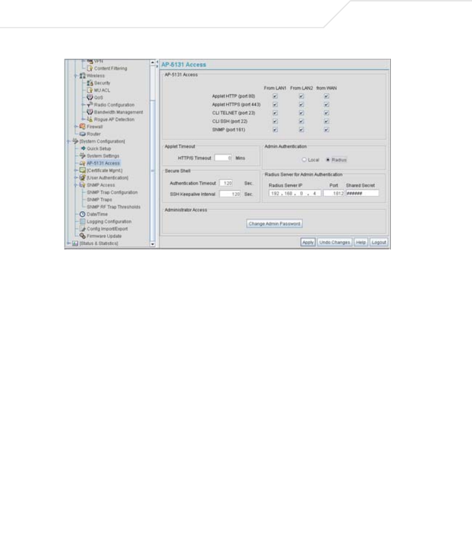
AP-51xx Access Point Product Reference Guide
4-6
2. Use the access point Access field checkboxes to enable/disable the following on the
access point’s LAN1, LAN2 or WAN interfaces:
3. Refer to the Applet Timeout field to set an HTTPS timeout interval.
Applet HTTP (port 80) Select the LAN1, LAN2 and/or WAN checkboxes to enable access
to the access point configuration applet using a Web browser.
Applet HTTPS (port
443)
Select the LAN1, LAN2 and/or WAN checkboxes to enable access
to the access point configuration applet using a Secure Sockets
Layer (SSL) for encrypted HTTP sessions.
CLI TELNET (port 23) Select the LAN1, LAN2 and/or WAN checkboxes to enable access
to the access point CLI via the TELNET terminal emulation TCP/IP
protocol.
CLI SSH (port 22) Select the LAN1, LAN2 and/or WAN checkboxes to enable access
to the access point CLI using the SSH (Secure Shell) protocol.
SNMP (port 161) Select the LAN1, LAN2 and/or WAN checkboxes to enable access
to the access point configuration settings from an SNMP-capable
client.
HTTP/S Timeout Disables access to the access point if no data activity is detected
over Applet HTTPS (port 443) after the user defined interval.
Default is 0 Mins.

System Configuration 4-7
4. Configure the Secure Shell field to set timeout values to reduce network inactivity.
5. Use the Admin Authentication buttons to specify the authentication server connection
method.
6. Use the Radius Server if a Radius server has been selected as the authentication server,
enter the required network address information.
Authentication
Timeout
Defines the maximum time (between 30 - 120 seconds) allowed for
SSH authentication to occur before executing a timeout. The
minimum permissible value is 30 seconds.
SSH Keepalive
Interval
The SSH Keepalive Interval defines a period (in seconds) after
which if no data has been received from a client, SSH sends a
message through the encrypted channel to request a response from
the client. The default is 0, and no messages will be sent to the
client until a non-zero value is set. Defining a Keepalive interval is
important, otherwise programs running on a server may never
notice if the other end of a connection is rebooted.
Local The access point verifies the authentication connection.
Radius Designates that a Radius server is used in the authentication
credential verification. If using this option, the connected PC is
required to have its Radius credentials verified with an external
Radius server. Additionally, the Radius Server’s Active Directory
should have a valid user configured and have a PAP based Remote
Access Policy configured for Radius Admin Authentication to work.
Radius Server IP Specify the numerical (non DNS name) IP address of the Remote
Authentication Dial-In User Service (Radius) server. Radius is a
client/server protocol and software enabling remote-access
servers to communicate with a server used to authenticate users
and authorize access to the requested system or service.
Port Specify the port on which the server is listening. The Radius server
typically listens on ports 1812 (default port).

AP-51xx Access Point Product Reference Guide
4-8
7. Update the Administrator Access field to change the administrative password used to
access the access point configuration settings.
8. Click Apply to save any changes to the access point Access screen. Navigating away from
the screen without clicking the Apply button results in all changes to the screen being lost.
9. Click Undo Changes (if necessary) to undo any changes made. Undo Changes reverts the
settings displayed on the access point Access screen to the last saved configuration.
10. Click Logout to securely exit the access point Symbol Access Point applet. A prompt
displays confirming the logout before the applet is closed.
4.3 Managing Certificate Authority (CA) Certificates
Certificate management includes the following sections:
•Importing a CA Certificate
•Creating Self Certificates for Accessing the VPN
4.3.1 Importing a CA Certificate
A certificate authority (CA) is a network authority that issues and manages security credentials and
public keys for message encryption. The CA signs all digital certificates that it issues with its own
private key. The corresponding public key is contained within the certificate and is called a CA
certificate. A browser must contain this CA certificate in its Trusted Root Library so that it can trust
certificates “signed” by the CA's private key.
Shared Secret Define a shared secret for authentication on the server. The shared
secret is required to be the same as the shared secret defined on
the Radius server. Use shared secrets to verify Radius messages
(with the exception of the Access-Request message) sent by a
Radius-enabled device configured with the same shared secret.
Apply the qualifications of a well-chosen password to the
generation of a shared secret. Generate a random, case-sensitive
string using letters, numbers and symbols. The default is symbol.
Change Admin
Password
Click the Change Admin Password button to display a screen
for updating the AP administrator password. Enter and confirm a
new administrator password as required.
System Configuration 4-9
Depending on the public key infrastructure, the digital certificate includes the owner's public key, the
certificate expiration date, the owner's name and other public key owner information.
The access point can import and maintain a set of CA certificates to use as an authentication option
for Virtual Private Network (VPN) access. To use the certificate for a VPN tunnel, define a tunnel and
select the IKE settings to use either RSA or DES certificates. For additional information on configuring
VPN tunnels, see Configuring VPN Tunnels on page 6-33.
Refer to your access point network administrator to obtain a CA certificate to import into the access
point.
To import a CA certificate:
1. Select System Configuration -> Certificate Mgmt -> CA Certificates from the access
point menu tree.
CAUTION Loaded and signed CA certificates will be lost when changing the
access point’s firmware version using either the GUI or CLI. After a
certificate has been successfully loaded, export it to a secure location
to ensure its availability after a firmware update.
NOTE Verify the access point device time is synchronized with an NTP server
before importing a certificate to avoid issues with conflicting date/time
stamps. For more information, see Configuring Network Time Protocol
(NTP) on page 4-31.
!
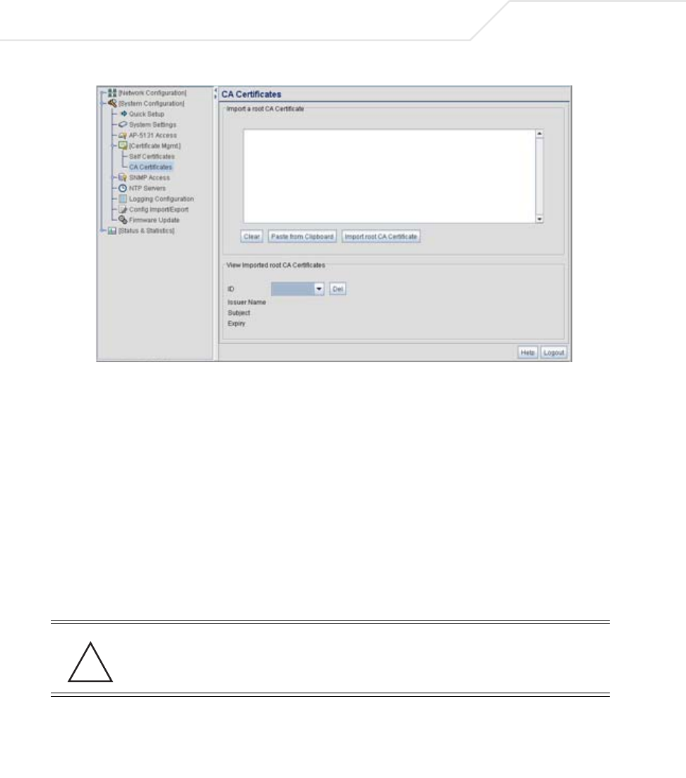
AP-51xx Access Point Product Reference Guide
4-10
2. Copy the content of the CA Certificate message (using a text editor such as notepad) and
then click on Paste from Clipboard.
The content of the certificate displays in the Import a root CA Certificate field.
3. Click the Import root CA Certificate button to import it into the CA Certificate list.
4. Once in the list, select the certificate ID within the View Imported root CA Certificates
field to view the certificate issuer name, subject, and certificate expiration data.
5. To delete a certificate, select the Id from the drop-down menu and click the Del button.
4.3.2 Creating Self Certificates for Accessing the VPN
The access point requires two kinds of certificates for accessing the VPN, CA certificates and self
certificates. Self certificates are certificate requests you create, send to a Certificate Authority (CA)
to be signed, then import the signed certificate into the management system.
To create a self certificate:
1. Select System Configuration -> Certificate Mgmt -> Self Certificates from the access
point menu tree.
CAUTION Self certificates can only be generated using the access point GUI and
CLI interfaces. No functionality exists for creating a self-certificate
using the access point’s SNMP configuration option.
!
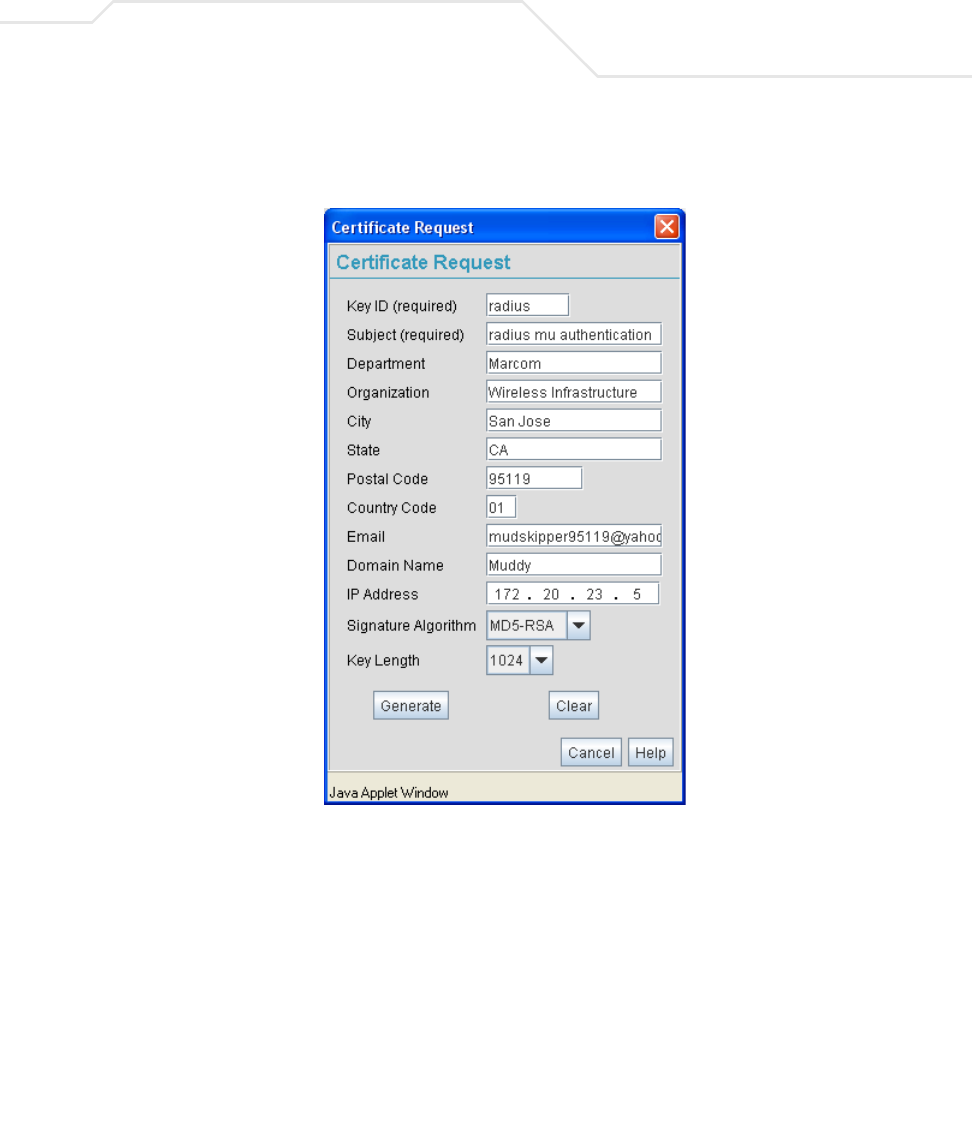
System Configuration 4-11
2. Click on the Add button to create the certificate request.
The Certificate Request screen displays.
3. Complete the request form with the pertinent information. Only 4 values are required, the
others optional:
Key ID Enter a logical name for the certificate to help distinguish between
certificates. The name can be up to 7 characters in length.
Subject The required Subject value contains important information about
the certificate. Contact the CA signing the certificate to determine
the content of the Subject parameter.
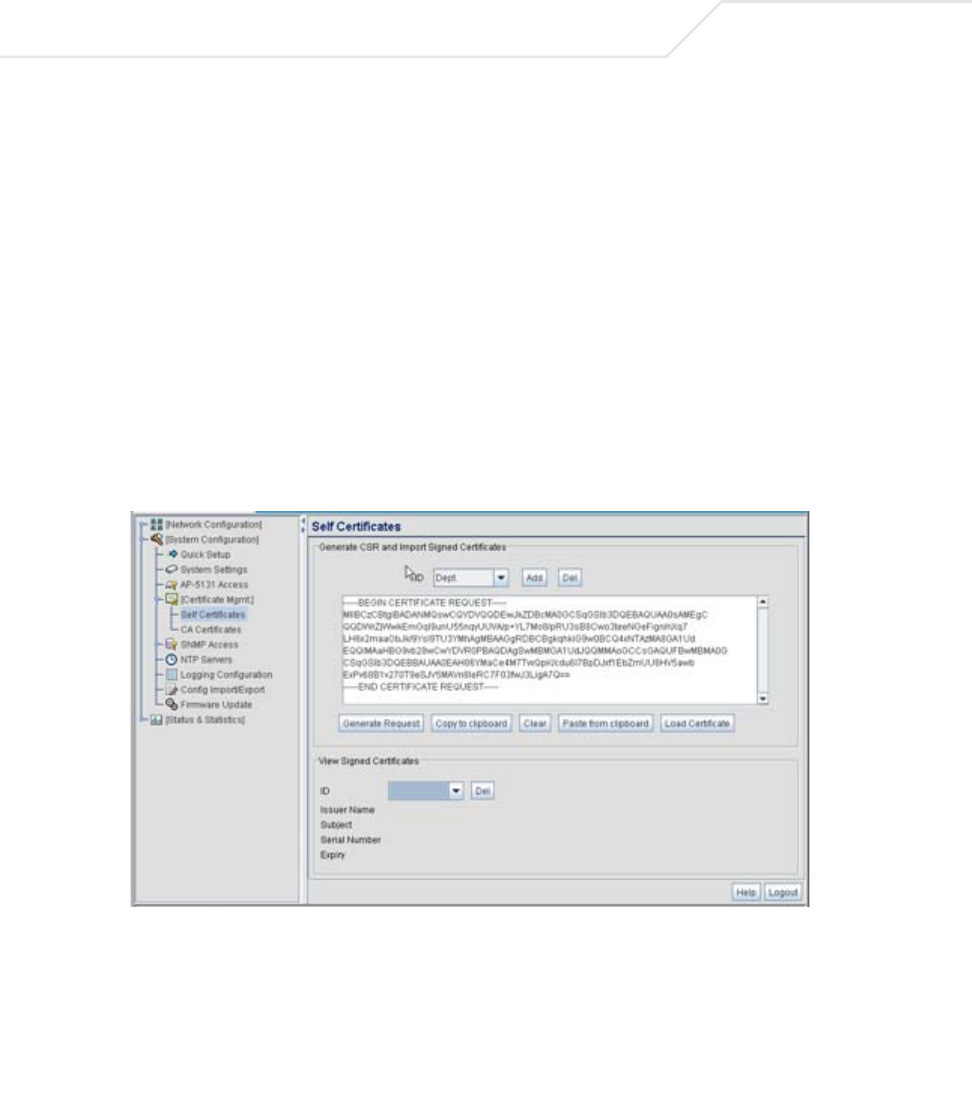
AP-51xx Access Point Product Reference Guide
4-12
4. When the form is completed, click the Generate button.
The Certificate Request screen disappears and the ID of the generated certificate request
displays in the drop-down list of certificates within the Self Certificates screen.
5. Click the Generate Request button.
The generated certificate request displays in Self Certificates screen text box.
6. Click the Copy to Clipboard button.
The content of certificate request is copied to the clipboard.
Create an email to your CA, paste the content of the request into the body of the message
and send it to the CA.
Signature Algorithm Use the drop-down menu to select the signature algorithm used for
the certificate. Options include:
• MD5-RSA - Message Digest 5 algorithm in combination with
RSA encryption.
• SHA1-RSA - Secure Hash Algorithm 1 in combination with
RSA encryption.
Key Length Defines the length of the key. Possible values are 512, 1024, and
2048.
System Configuration 4-13
The CA signs the certificate and will send it back. Once received, copy the content from the
email into the clipboard.
7. Click the Paste from clipboard button.
The content of the email displays in the window.
Click the Load Certificate button to import the certificate and make it available for use as
a VPN authentication option. The certificate ID displays in the Signed list.
8. To use the certificate for a VPN tunnel, first define a tunnel and select the IKE settings to
use either RSA or DES certificates. For additional information on configuring VPN tunnels,
see Configuring VPN Tunnels on page 6-33.
4.3.3 Creating a Certificate for Onboard Radius Authentication
The access point can use its on-board Radius Server to generate certificates to authenticate MUs for
use with the access point. In addition, a Windows 2000 or 2003 Server is used to sign the certificate
before downloading it back to the access point’s on-board Radius server and loading the certificate
for use with the access point.
Both a CA and Self certificate are required for Onboard Radius Authentication. For information on CA
Certificates, see Importing a CA Certificate on page 4-8. Ensure the certificate is in a Base 64
Encoded format or risk loading an invalid certificate.
To create a self certificate for on-board Radius authentication:
1. Select System Configuration -> Certificate Mgmt -> Self Certificates from the access
point menu tree.
2. Click on the Add button to create the certificate request.
The Certificate Request screen displays.
NOTE If the access point is restarted after a certificate request has been
generated but before the signed certificate is imported, the import will not
execute properly. Do not restart the access point during this process.
CAUTION Self certificates can only be generated using the access point GUI and
CLI interfaces. No functionality exists for creating a self-certificate
using the access point’s SNMP configuration option.
!

AP-51xx Access Point Product Reference Guide
4-14
3. Complete the request form with the pertinent information.
Key ID (required) Enter a logical name for the certificate to help distinguish between
certificates. The name can be up to 7 characters in length.
Subject (required) The required Subject value contains important information about
the certificate. Contact the CA signing the certificate to determine
the content of the Subject parameter.
Department Optionally enter a value for your organizations’s department name
if needing to differentiate the certificate from similar certificates
used in other departments within your organization.
Organization Optionally enter the name of your organization for supporting
information for the certificate request.
City Optionally enter the name of the City where the access point (using
the certificate) resides.
State Optionally enter the name of the State where the access point
(using the certificate) resides.
Postal Code Optionally enter the name of the Postal (Zip) Code where the
access point (using the certificate) resides.
Country Code Optionally enter the access point’s Country Code.
Email Enter a organizational email address (avoid using a personal
address if possible) to associate the request with the proper
requesting organization.
Domain Name Ensure the Domain name is the name of the CA Server. This value
must be set correctly to ensure the certificate is properly
generated.
IP Address Enter the IP address of this access point (as you are using the
access point’s onbard Radius server).
Signature Algorithm Use the drop-down menu to select the signature algorithm used for
the certificate. Options include:
• MD5-RSA - Message Digest 5 algorithm in combination with
RSA encryption.
• SHA1-RSA - Secure Hash Algorithm 1 in combination with
RSA encryption.
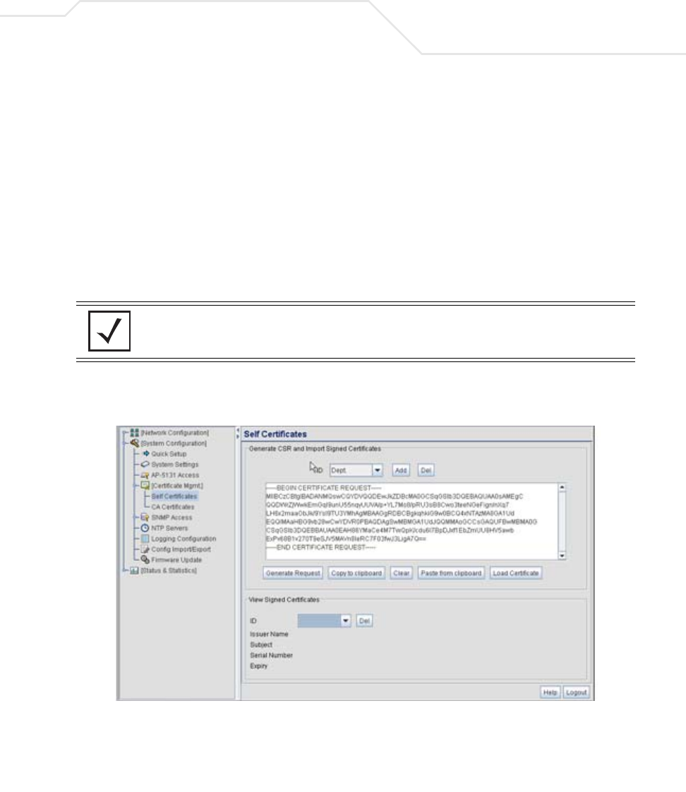
System Configuration 4-15
4. Complete as many of the optional values within the Certificate Request screen as
possible.
5. When the form is completed, click the Generate button from within the Certificate Request
screen.
The Certificate Request screen disappears and the ID of the generated certificate request
displays in the drop-down list of certificates within the Self Certificates screen.
6. Click the Generate Request button from within the Self Certificates screen. The certificate
content displays within the Self Certificate screen.
7. Click the Copy to clipboard button. Save the certificate content to a secure location.
8. Connect to the Windows 2000 or 2003 server used to sign the certificate.
9. Select the Request a certificate option. Click Next to continue.
Key Length Defines the length of the key. Possible values are 512, 1024, and
2048. Symbol recommends setting this value to 1024 to ensure
optimum functionality.
NOTE A Warning screen may display at this phase stating key information could
be lost if you proceed with the certificate request. Click the OK button to
continue, as the certificate has not been signed yet.
AP-51xx Access Point Product Reference Guide
4-16
10. Select the Advanced request checkbox from within the Choose Request Type screen and
click Next to continue.
11. From within the Advanced Certificate Requests screen, select the Submit a certificate
request using a base 64 encoded PKCS #10 file or a renewal request using a
base64 encoded PKCS file option. Click Next to continue.
12. Paste the content of certificate in the Saved Request field (within the Submit a Saved
Request screen).
If you do not have administrative privileges, ensure the Web Server option has been
selected from the Certificate Template drop-down menu. Click Submit.
13. Select the Base 64 encoded checkbox option from within the Certificate Issued screen and
select the Download CA Certificate link.
A File Download screen displays prompting the user to select the download location for
the certificate.
14. Click the Save button and save the certificate to a secure location.
15. Load the certificates on the access point.
16. Open the certificate file and copy its contents into the CA Certificates screen by clicking the
Paste from Clipboard button.
The certificate is now ready to be loaded into the access point’s flash memory.
17. Click the Import root CA Certificate button from within the CA Certificates screen.
18. Verify the contents of the certificate file display correctly within the CA Certificates screen.
19. Open the certificate file and copy its contents into the Self Certificates screen by clicking
the Paste from Clipboard button.
20. Click the Load Certificate button.
21. Verify the contents of the certificate file display correctly within the Self Certificates screen.
The certificate for the onboard Radius authentication of MUs has now been generated and
loaded into the access point’s flash memory.
NOTE An administrator must make sure the Web Server option is available as a
selectable option for those without administrative privileges.
CAUTION Ensure the CA Certificate is loaded before the Self Certificate, or risk
an invalid certificate load.
!
System Configuration 4-17
4.4 Configuring SNMP Settings
Simple Network Management Protocol (SNMP) facilitates the exchange of management information
between network devices. SNMP uses Management Information Bases (MIBs) to manage the device
configuration and monitor Internet devices in potentially remote locations. MIB information accessed
via SNMP is defined by a set of managed objects called object identifiers (OIDs). An object identifier
(OID) is used to uniquely identify each object variable of a MIB. The access point Web download
package contains the following 2 MIB files:
• Symbol-CC-WS2000-MIB-2.0 (common Symbol MIB file)
• Symbol-AP-5131-MIB (AP-5131 specific MIB file)
If using the Symbol-CC-WS2000-MIB-2.0 and/or Symbol-AP-5131-MIB to configure the AP-5131, use
the table below to locate the MIB where the feature can be configured.
NOTE The Symbol-AP-5131-MIB contains the majority of the information
contained within the Symbol-CC-WS2000-MIB-2.0 file. This feature rich
information has been validated with the Symbol WS2000 and proven
reliable. The remaining portion of the Symbol-AP-5131-MIB contains
supplemental information unique to the access point feature set.
Feature MIB Feature MIB
LAN Configuration Symbol-AP-5131-MIB Subnet Configuration Symbol-CC-WS2000-MIB-2.0
VLAN Configuration Symbol-AP-5131-MIB DHCP Server
Configuration
Symbol-CC-WS2000-MIB-2.0
802.1x Port
Authentication
Symbol-AP-5131-MIB Advanced DHCP
Server configuration
Symbol-CC-WS2000-MIB-2.0
Ethernet Type Filter
Configuration
Symbol-AP-5131-MIB WAN IP Configuration Symbol-CC-WS2000-MIB-2.0
Wireless
Configuration
Symbol-AP-5131-MIB PPP Over Ethernet Symbol-CC-WS2000-MIB-2.0
Security Configuration Symbol-AP-5131-MIB NAT Address Mapping Symbol-CC-WS2000-MIB-2.0
MU ACL Configuration Symbol-AP-5131-MIB VPN Tunnel
Configuration
Symbol-CC-WS2000-MIB-2.0
QOS Configuration Symbol-AP-5131-MIB VPN Tunnel status Symbol-CC-WS2000-MIB-2.0

AP-51xx Access Point Product Reference Guide
4-18
SNMP allows a network administrator to manage network performance, find and solve network
problems, and plan for network growth. The access point supports SNMP management functions for
gathering information from its network components, communicating that information to specified
users and configuring the access point. All the fields available within the access point are also
configurable within the MIB.
Radio Configuration Symbol-AP-5131-MIB Content Filtering Symbol-CC-WS2000-MIB-2.0
Bandwidth
Management
Symbol-AP-5131-MIB Rogue AP Detection Symbol-CC-WS2000-MIB-2.0
SNMP Trap Selection Symbol-AP-5131-MIB Firewall Configuration Symbol-CC-WS2000-MIB-2.0
SNMP RF Trap
Thresholds
Symbol-AP-5131-MIB LAN to WAN Access Symbol-CC-WS2000-MIB-2.0
Config Import/Export Symbol-AP-5131-MIB Advanced LAN Access Symbol-CC-WS2000-MIB-2.0
MU Authentication
Stats
Symbol-AP-5131-MIB Router Configuration Symbol-CC-WS2000-MIB-2.0
Feature MIB Feature MIB
WNMP Ping
Configuration
Symbol-AP-5131-MIB System Settings Symbol-CC-WS2000-MIB-2.0
Known AP Stats Symbol-AP-5131-MIB AP 5131 Access Symbol-CC-WS2000-MIB-2.0
Flash LEDs Symbol-AP-5131-MIB Certificate Mgt Symbol-CC-WS2000-MIB-2.0
Automatic Update Symbol-AP-5131-MIB SNMP Access
Configuration
Symbol-CC-WS2000-MIB-2.0
SNMP Trap
Configuration
Symbol-CC-WS2000-MIB-2.0
NTP Server
Configuration
Symbol-CC-WS2000-MIB-2.0
Logging Configuration Symbol-CC-WS2000-MIB-2.0
Firmware Update Symbol-CC-WS2000-MIB-2.0
Wireless Stats Symbol-CC-WS2000-MIB-2.0
Radio Stats Symbol-CC-WS2000-MIB-2.0
MU Stats Symbol-CC-WS2000-MIB-2.0
Automatic Update Symbol-CC-WS2000-MIB-2.0