SystemBase SG-1020WALL Serialgate User Manual Manual 1
SystemBase Co., Ltd. Serialgate Manual 1
UserManual.wiki
>
SystemBase
>
SG-1020WALL User Manual
>
Manual 1
Contents
1.
Manual 1
2.
Manual 2
Manual 1
Navigation menu
Upload a User Manual
Namespaces
Wiki Guide
HTML
PDF
Info
Views
User Manual
Discussion / Help
Navigation
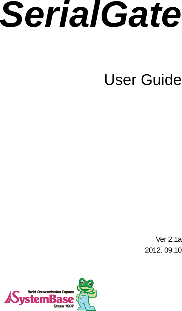
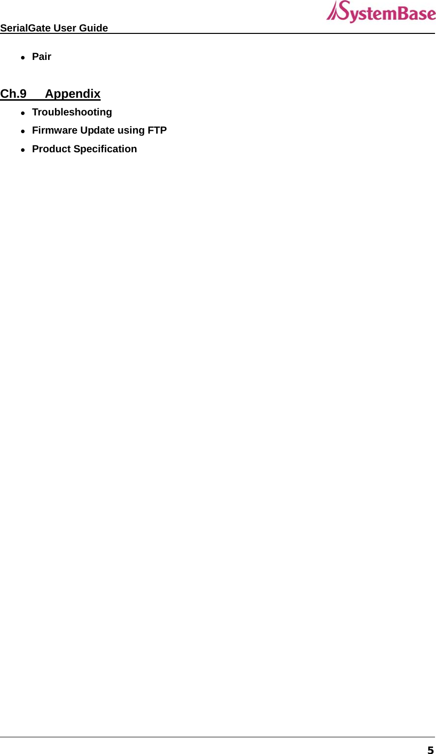
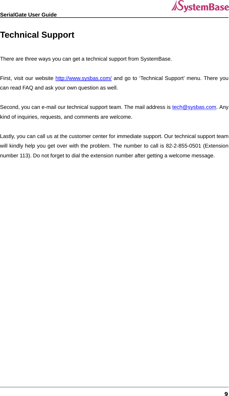

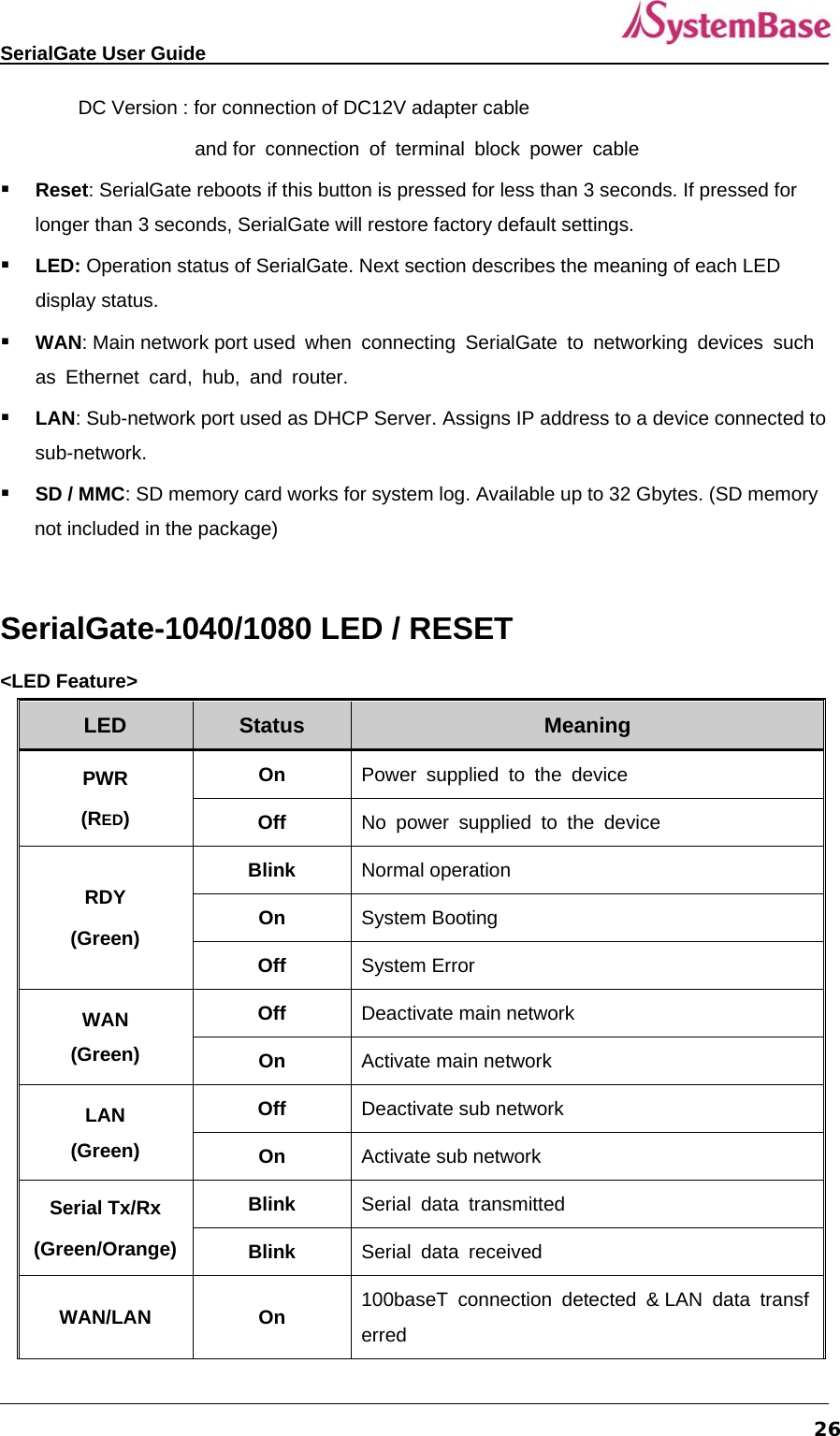
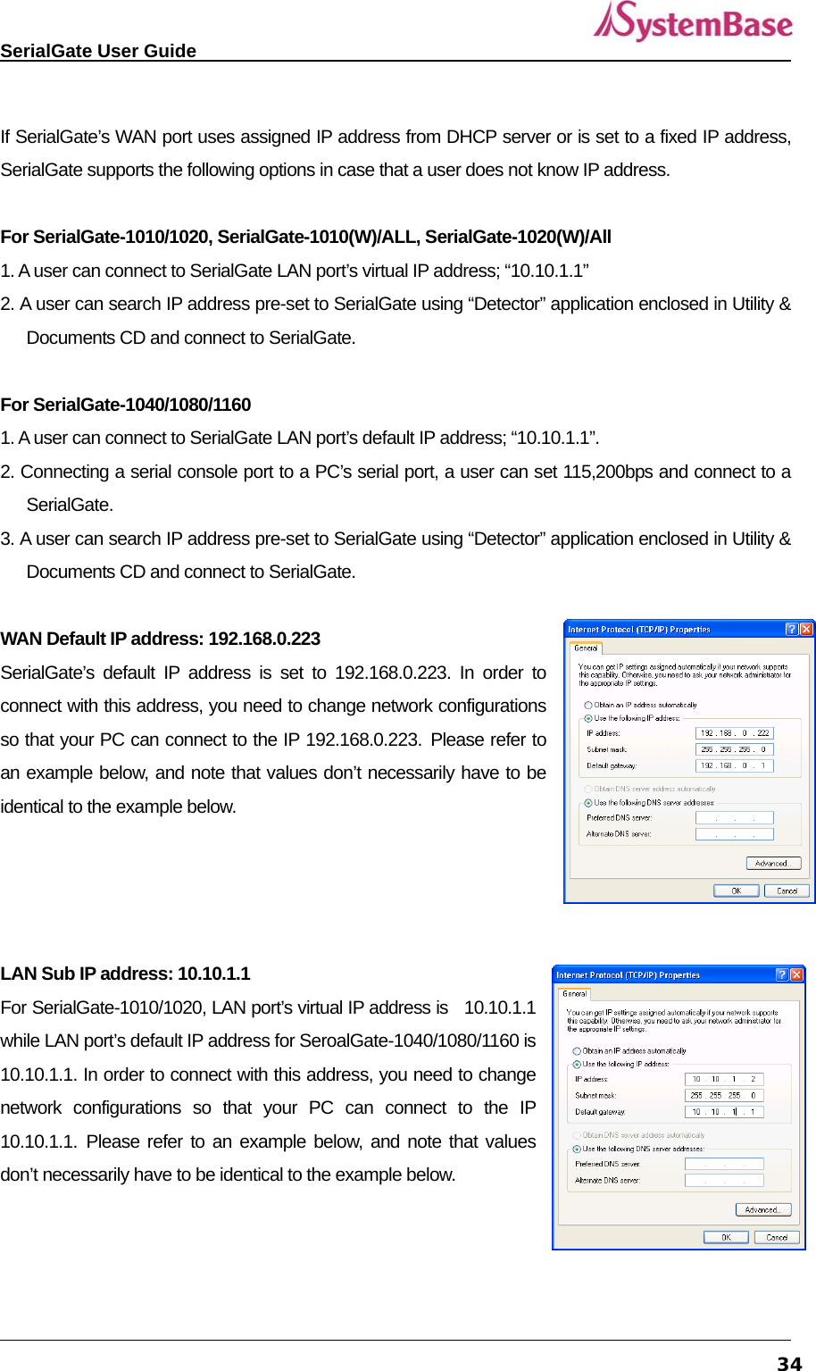
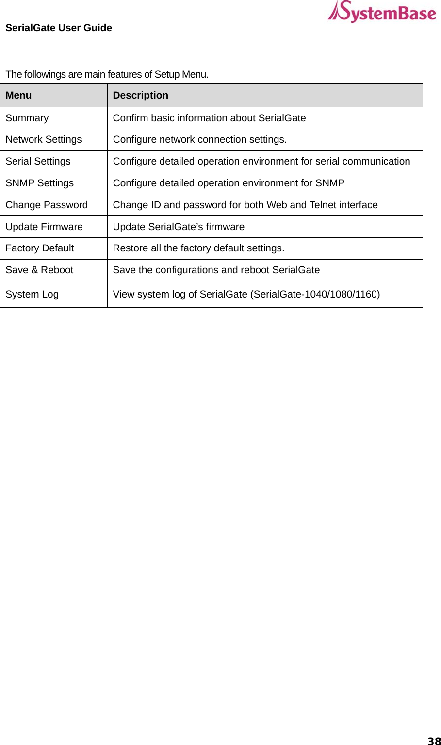
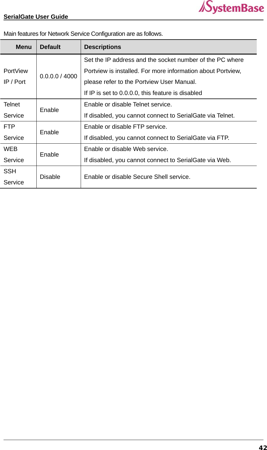
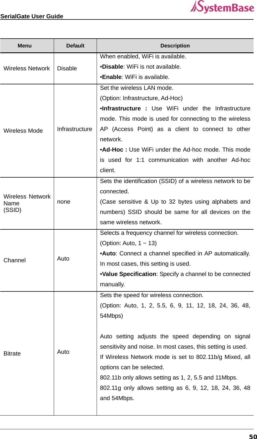
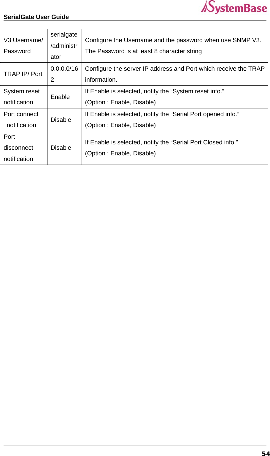

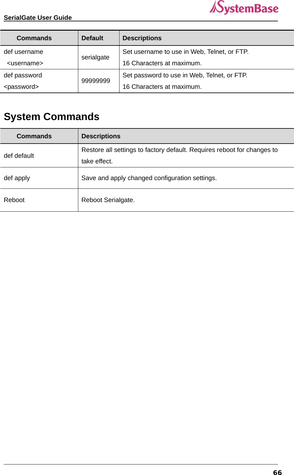
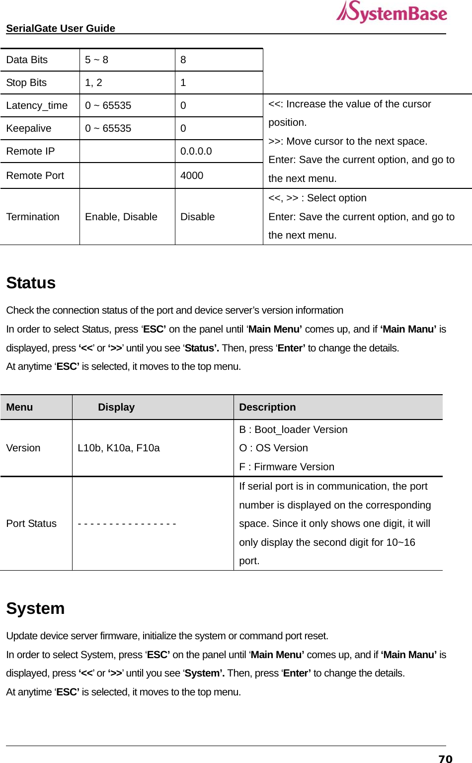
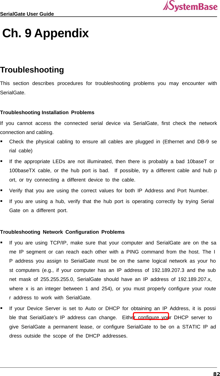
![SerialGate User Guide 60Ch. 6 Configuration via Telnet Connection Open your telnet client program and enter SerialGate’s IP address to connect. You need to enter appropriate username and password to login. Please note that this username and password is used as authentication method for Web as well. This means if username or/and password has been modified from the telnet interface, modified values have to be entered to connect to web, and vice versa. ◆ Factory default username : serialgate ◆ Factory default password : 99999999 [def] commands - you can configure SerialGate’s settings. [def help] commands - you can view current SerialGate’s settings. After changing values, you can see modified values with ‘set view’ commands. But, be careful because these values are not in effect unless you issue a ‘def save’ command. Changes will be discarded if you do not save current settings.](https://usermanual.wiki/SystemBase/SG-1020WALL.Manual-1/User-Guide-1802390-Page-60.png)
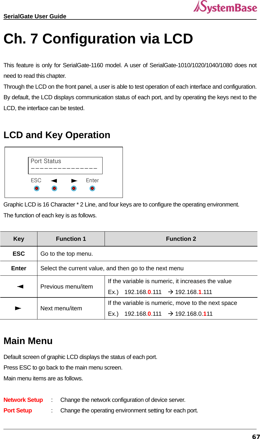
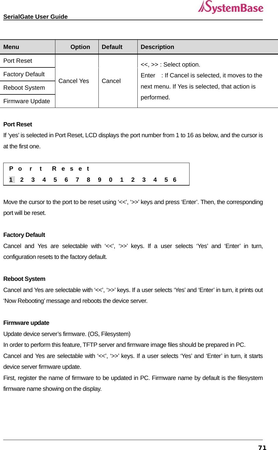
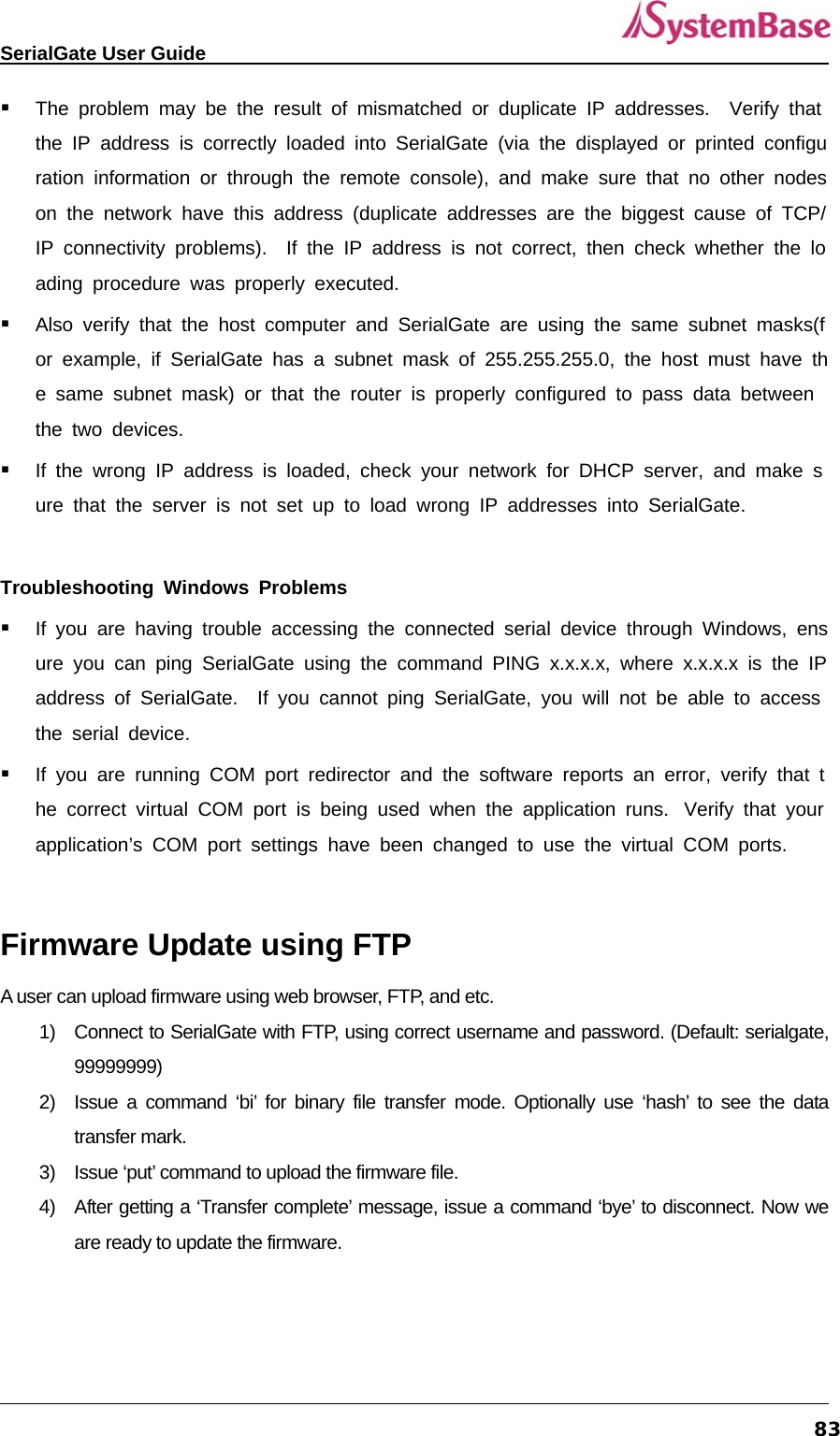
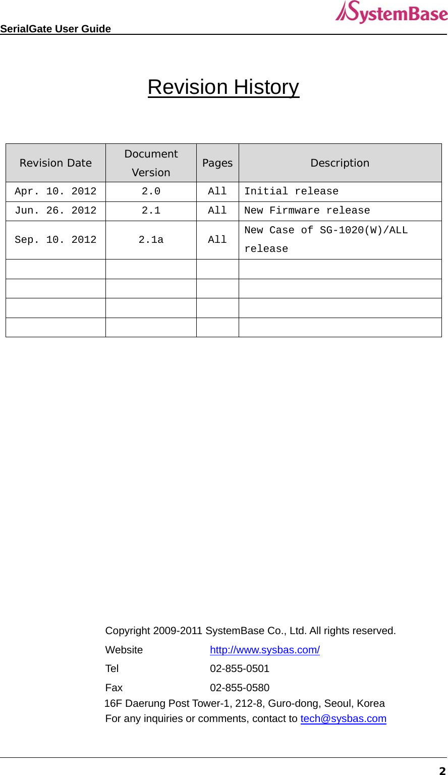
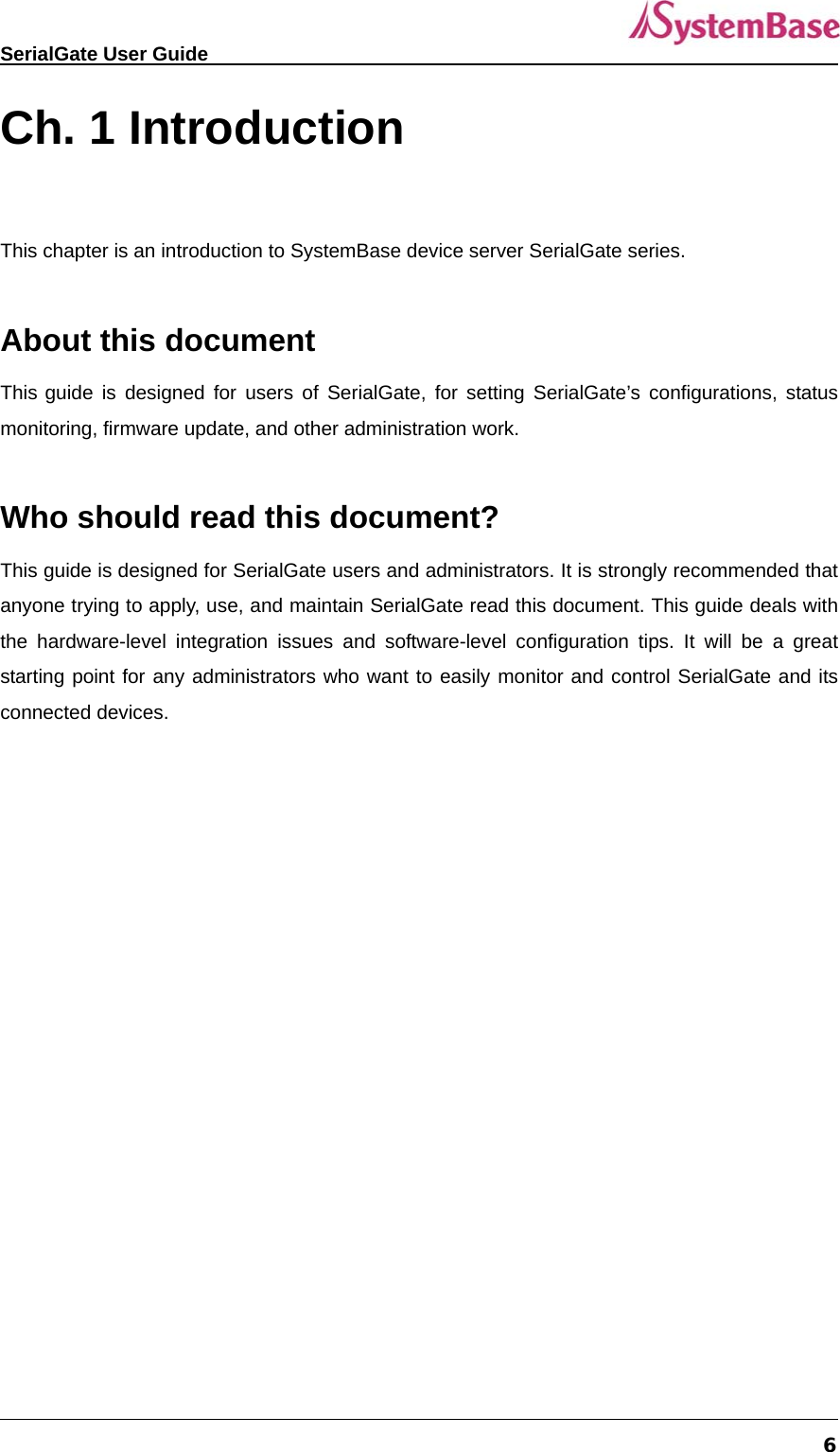
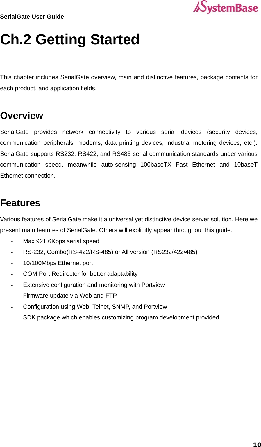
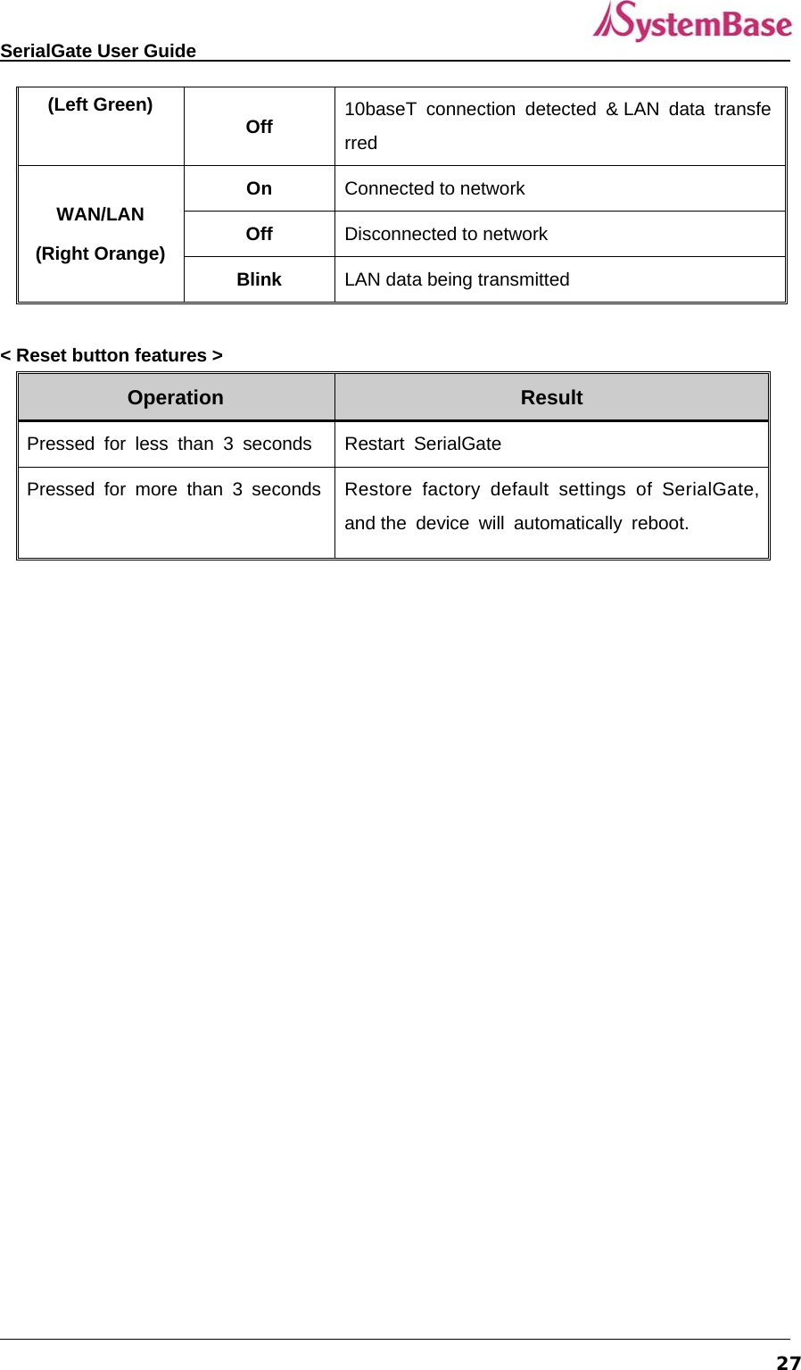
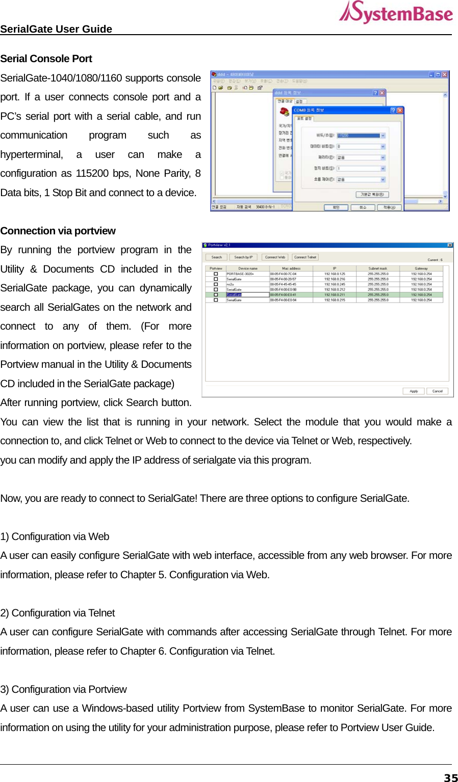
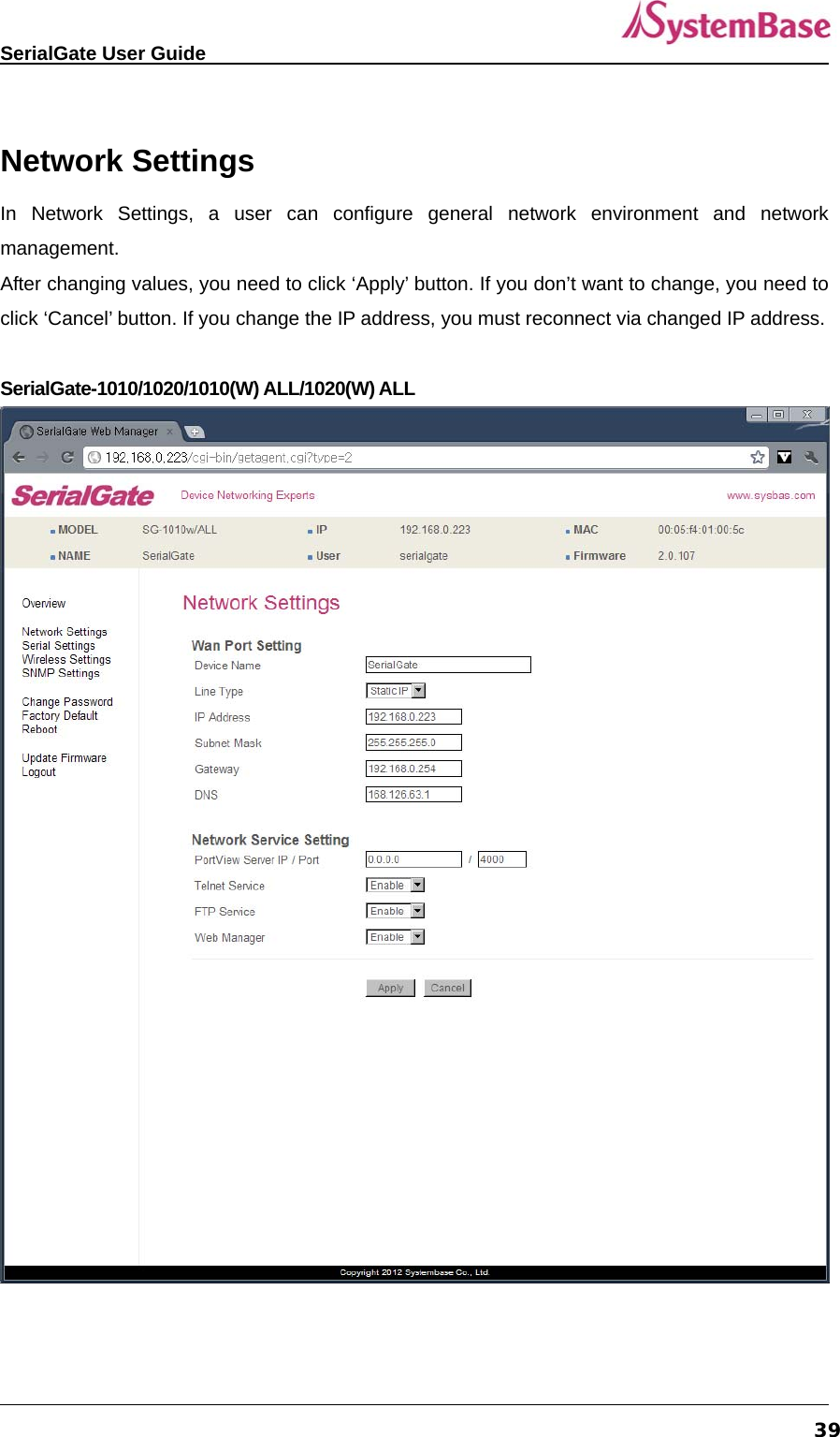
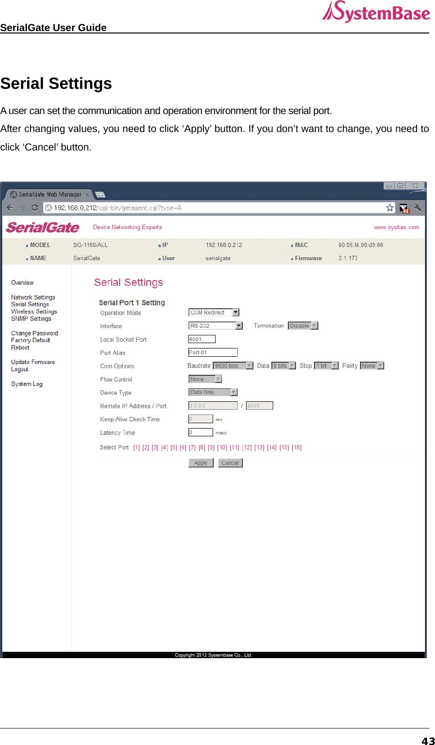
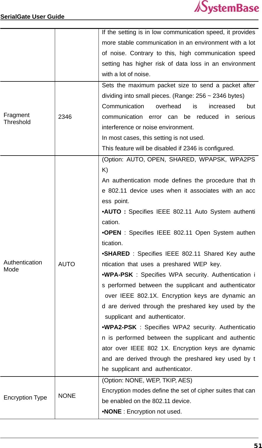
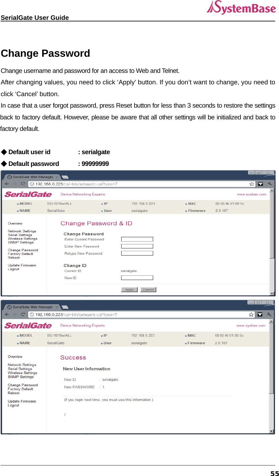
![SerialGate User Guide 61 View Commands Commands related to View are as follows. Command Description def view Show all information about SerialGate def view wan Show WAN network settings def view management Show managing items settings def view serial Show serial port settings def help Show command list and help Network Commands Commands related to configuration of general network environment and network management are as follows. Command Default Description def mac <Mac Address> 00:05:f4:00:20:57 Register SerialGate’s MAC address def line [ip/dhcp] Static IP IP obtaining method for SerialGate’s network connection def ip <IP Address> 192.168.0.223 Display the current IP address If line type is Static IP, manually enter an appropriate IP address. If line type is DHCP, it is not editable. Instead, current IP address is shown. def mask <Subnet mask> 255.255.255.0 Display the current subnet mask address If line type is Static IP, manually enter an appropriate subnet mask address. If line type is DHCP, it is not editable. Instead, current subnet mask address is shown def gateway <Gateway address> 192.168.0.1 Display the current Gateway address If line type is Static IP, manually enter an appropriate Gateway address.](https://usermanual.wiki/SystemBase/SG-1020WALL.Manual-1/User-Guide-1802390-Page-61.png)
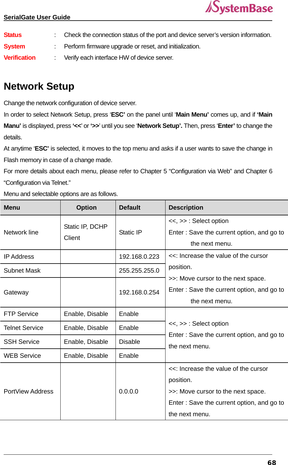
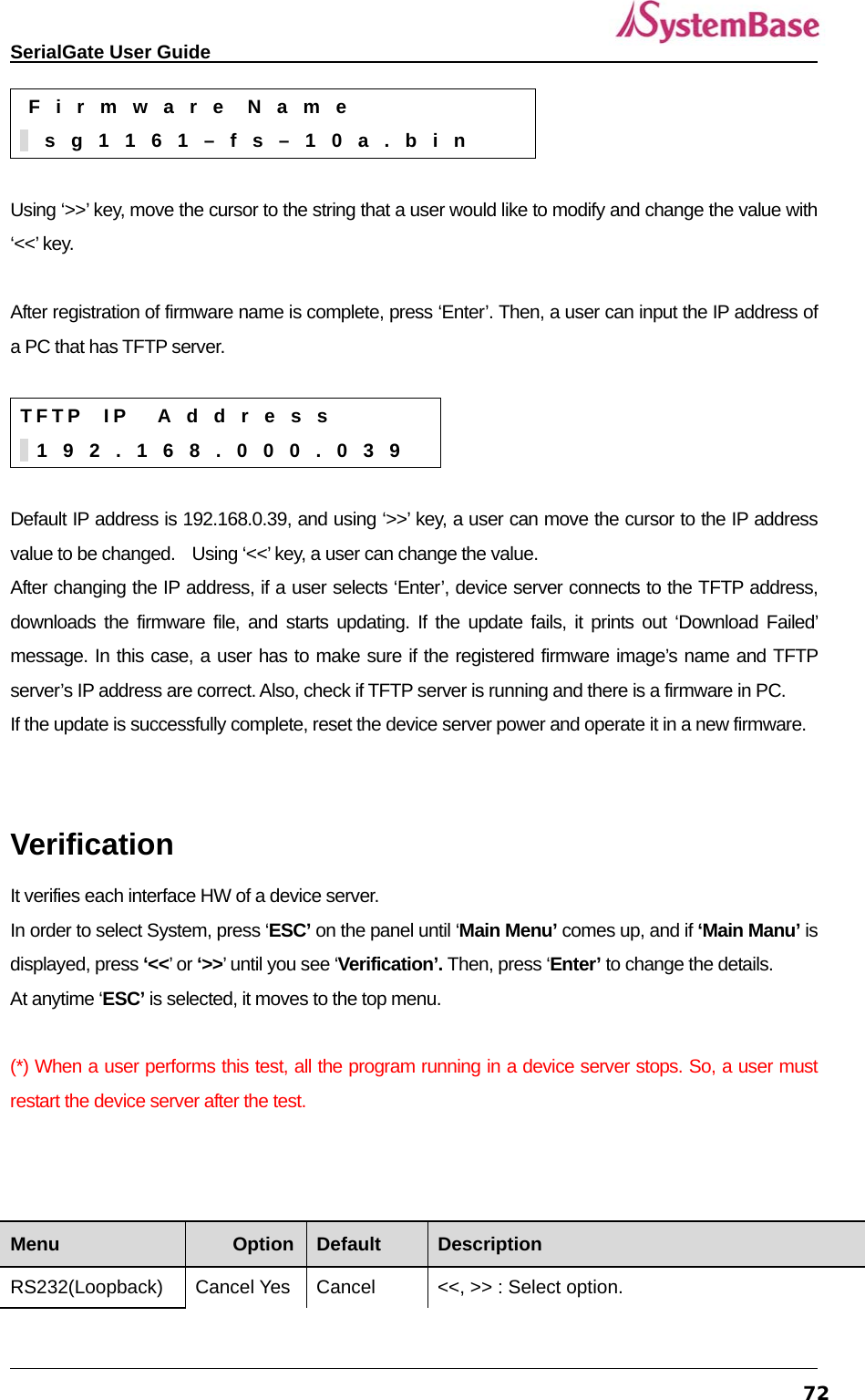
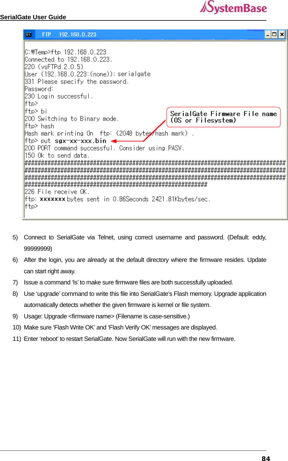
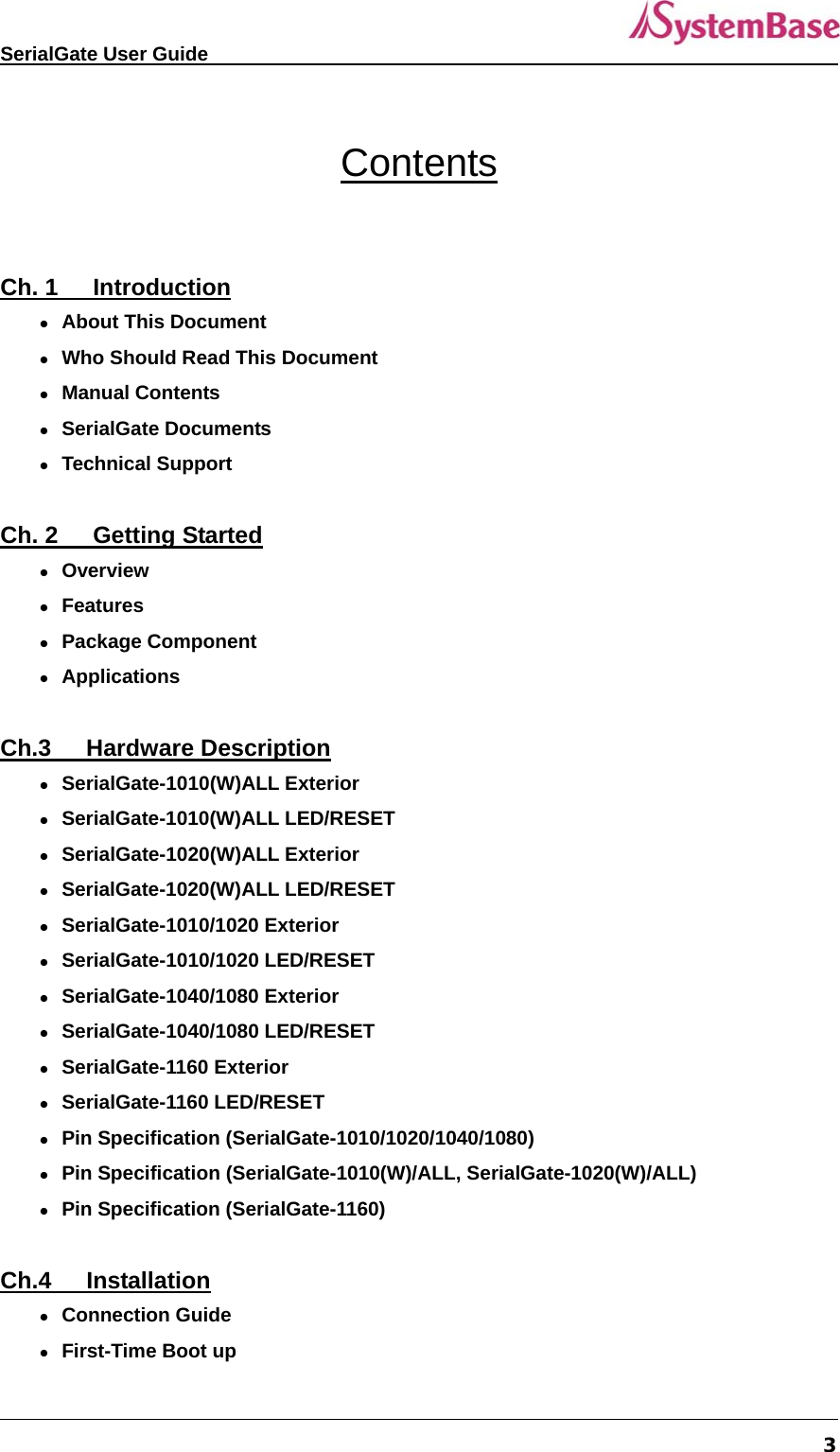
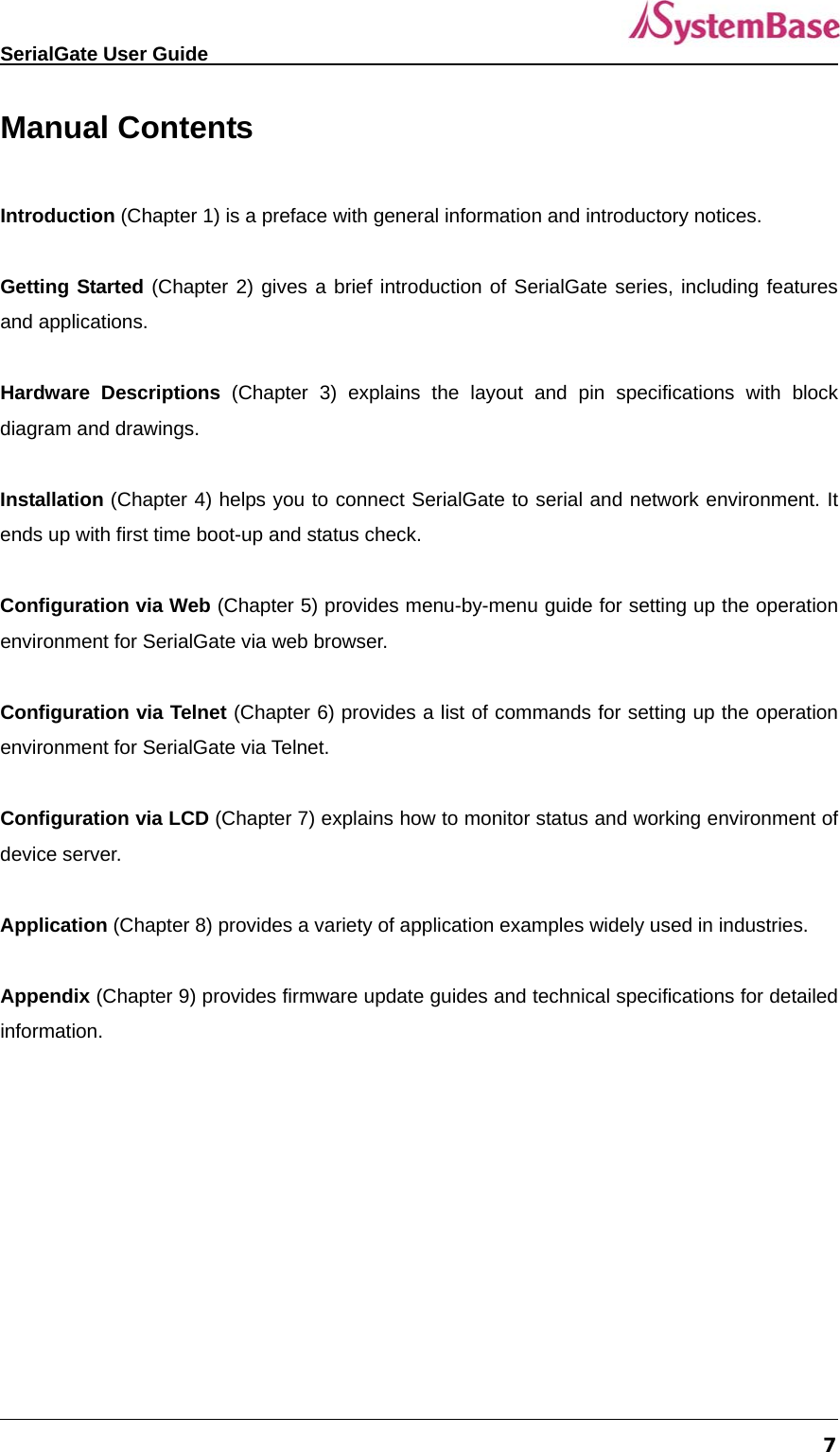
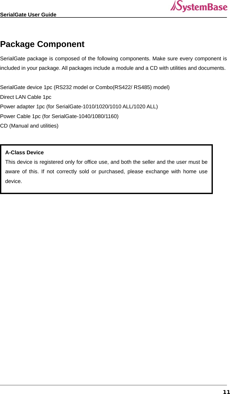
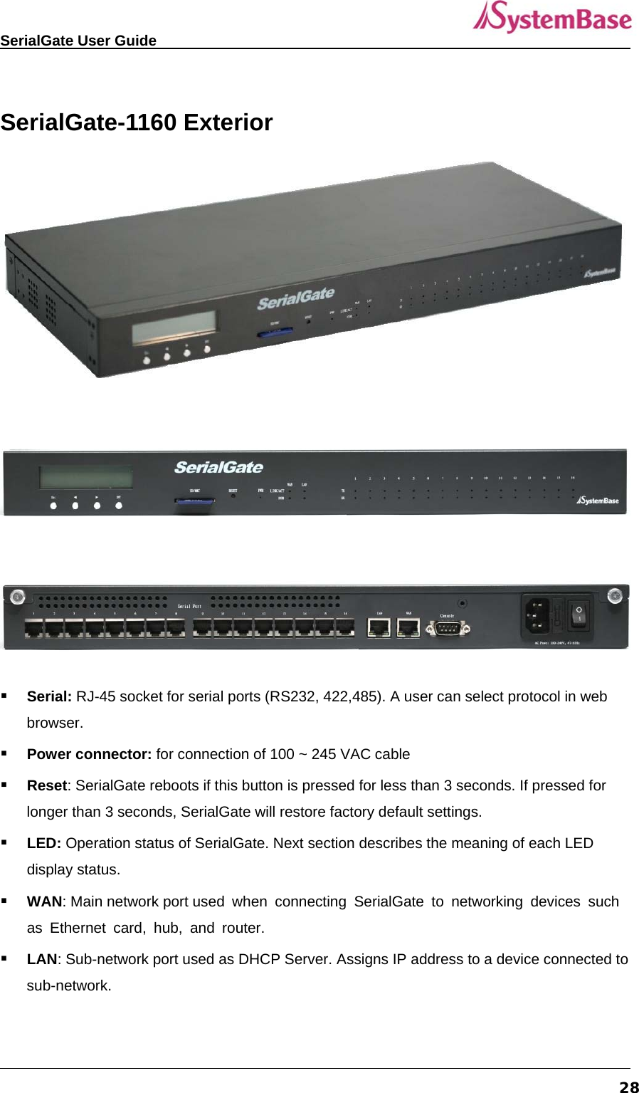
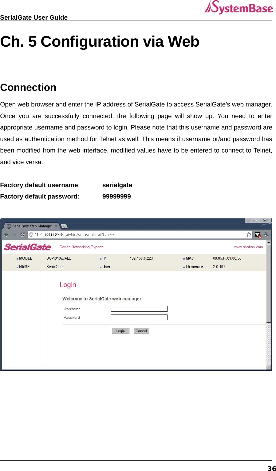
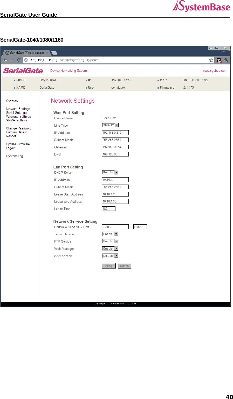
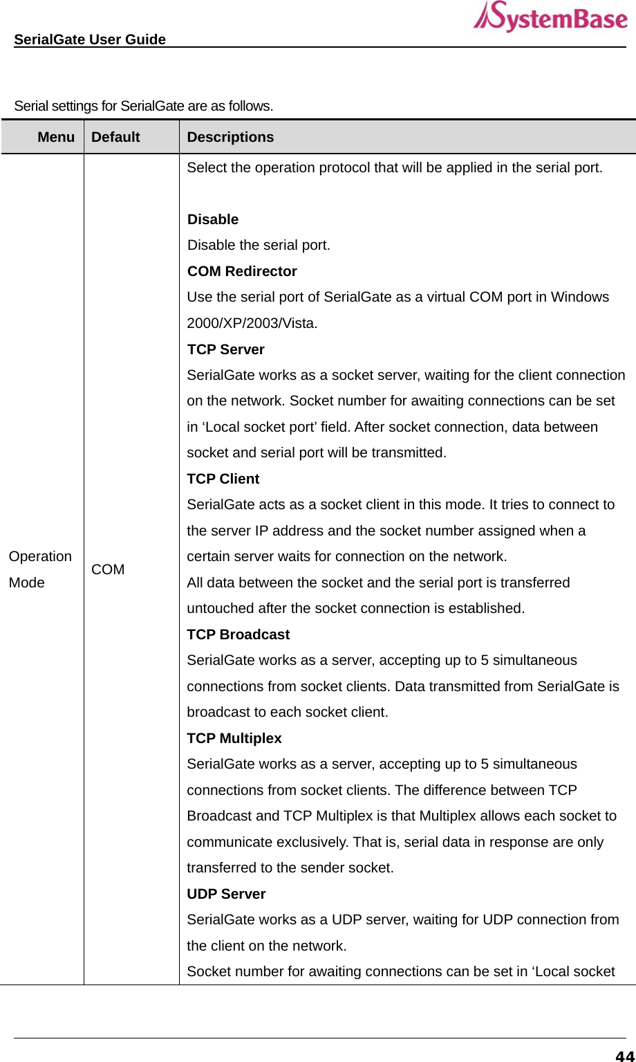
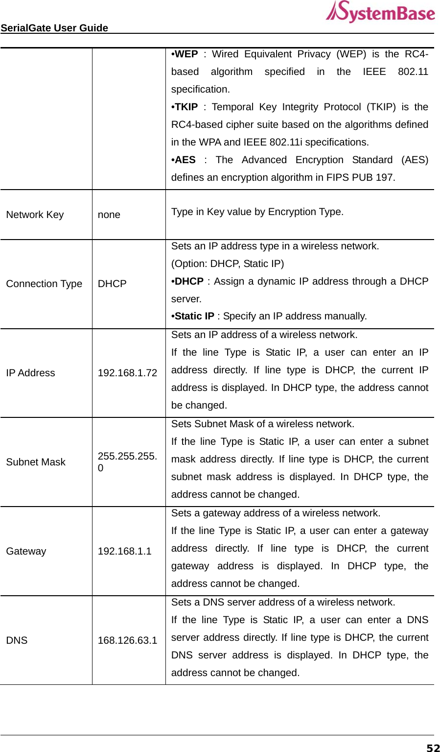
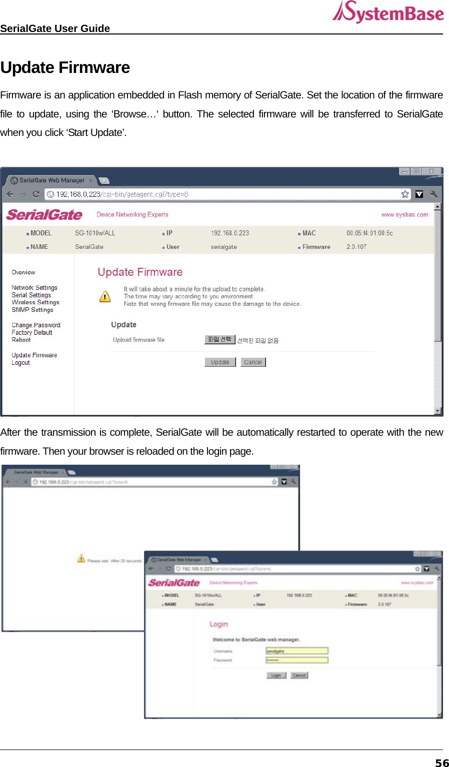
![SerialGate User Guide 62If line type is DHCP, it is not editable. Instead, current Gateway address is shown def dns <IP Address> 168.126.63.1 Set IP address of Domain Name Service def portviewip <IP address> 0.0.0.0 Configures IP of PC which Portview is installed If IP is set to 0.0.0.0, Portview feature is disabled. (Please refer to Portview User Manual in SerialGate Utility & Documents CD for detailed information.) def portviewport <Port number> 4000 Set the socket number of a PC which Portview is installed.def ftp [enable/ disable] Enable Enable or disable FTP service. If disabled, you cannot connect to SerialGate via FTP. def telnet [enable/ disable] Enable Enable or disable Telnet service. If disabled, you cannot connect to SerialGate via Telnet. def web [enable/ disable] Enable Enable or disable Web service. If disabled, you cannot connect to SerialGate via Web. def ssh [enable/ disable] Disable Enable or disable SSH service. If enabled, you can connect to SerialGate via SSH. def ddns [IP Address] 203.32.117.1 If you set DDNS server IP, DDNS service will be enable. But if you set “0.0.0.0”, this service will be disabled. def ddnsuser [username] serialgate Set username to access DDNS server. def ddnspass [password] 99999999 Set password to access DDNS server. def name [SerialGate name] Product Name Set the name of SerialGate. (Max 32 bytes) def snmp [enable/ disable] Disable Enable or disable SNMP(Simple Network Management Protocol) - MIB-II(RFC 1213): System, Interface, IP, ICMP, TCP, UDP - MIB-I (RFC 1317): Serial Interface def v1readwrite [enable, disable] Disable SNMP V1/2 Attributes can read and write by SNMP Agent. In order to read attributes only, change the feature to "ReadOnly.”](https://usermanual.wiki/SystemBase/SG-1020WALL.Manual-1/User-Guide-1802390-Page-62.png)
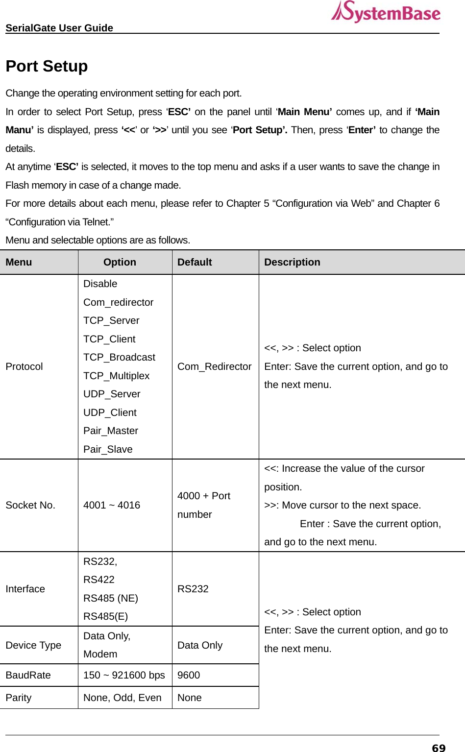
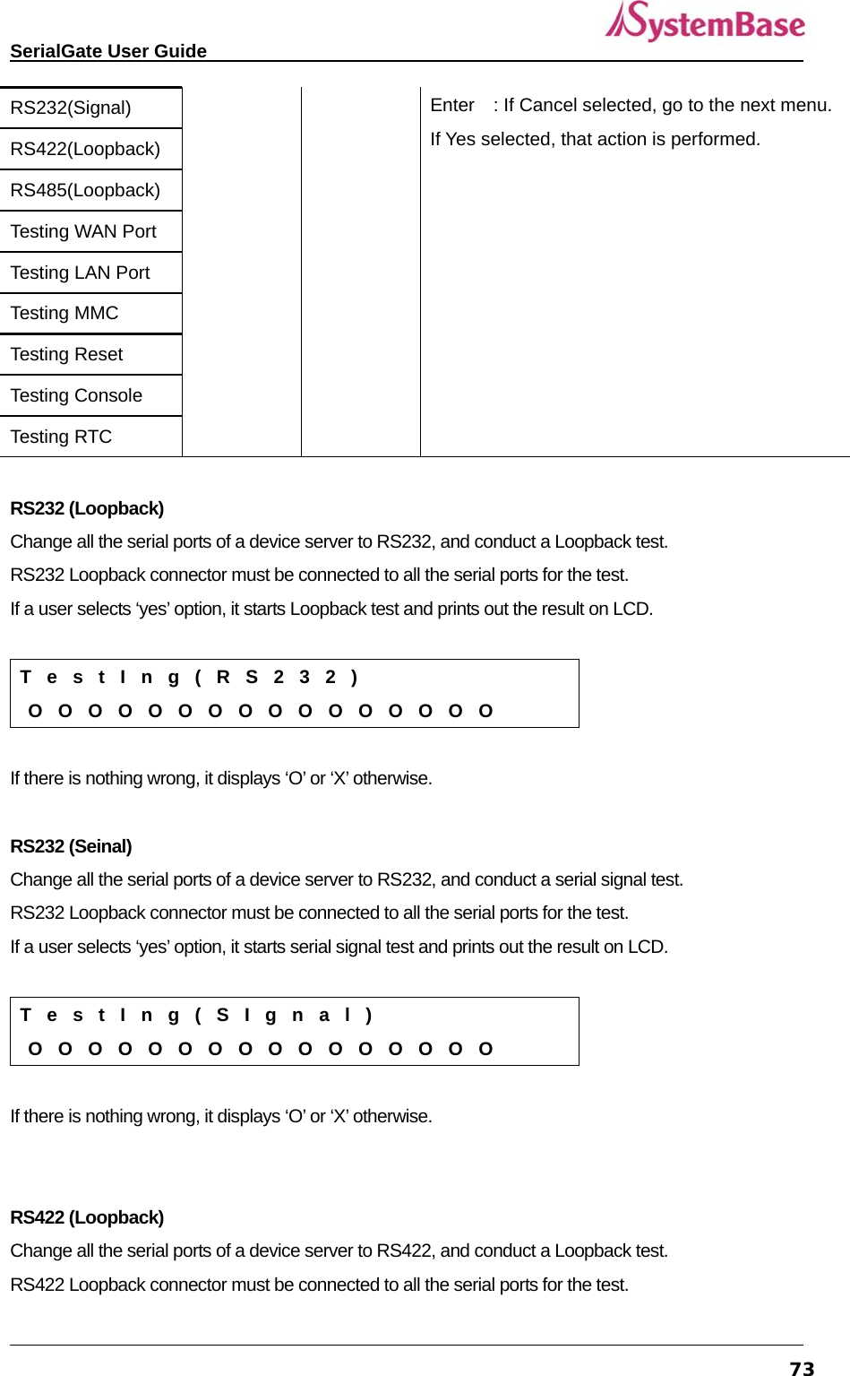
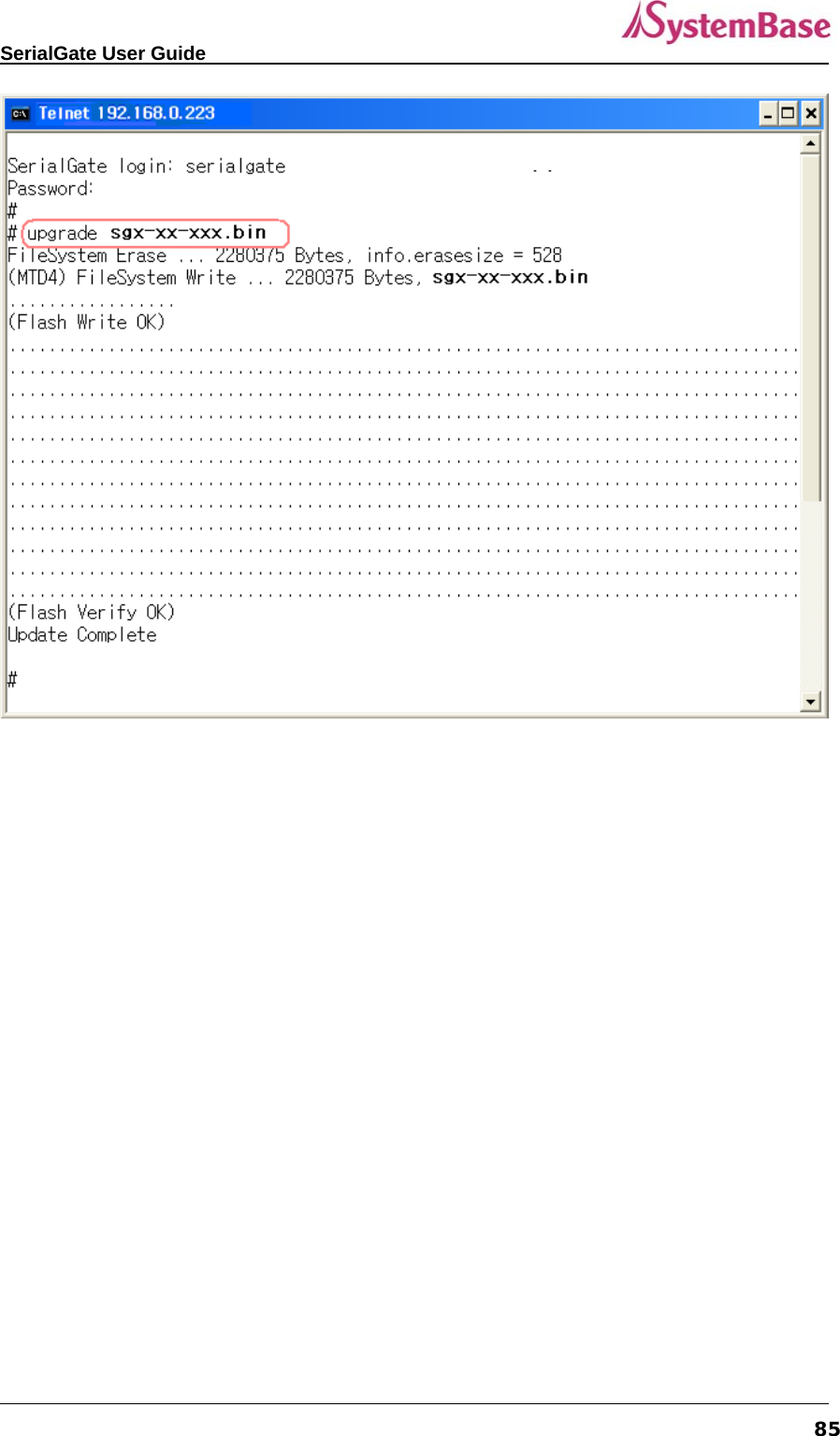
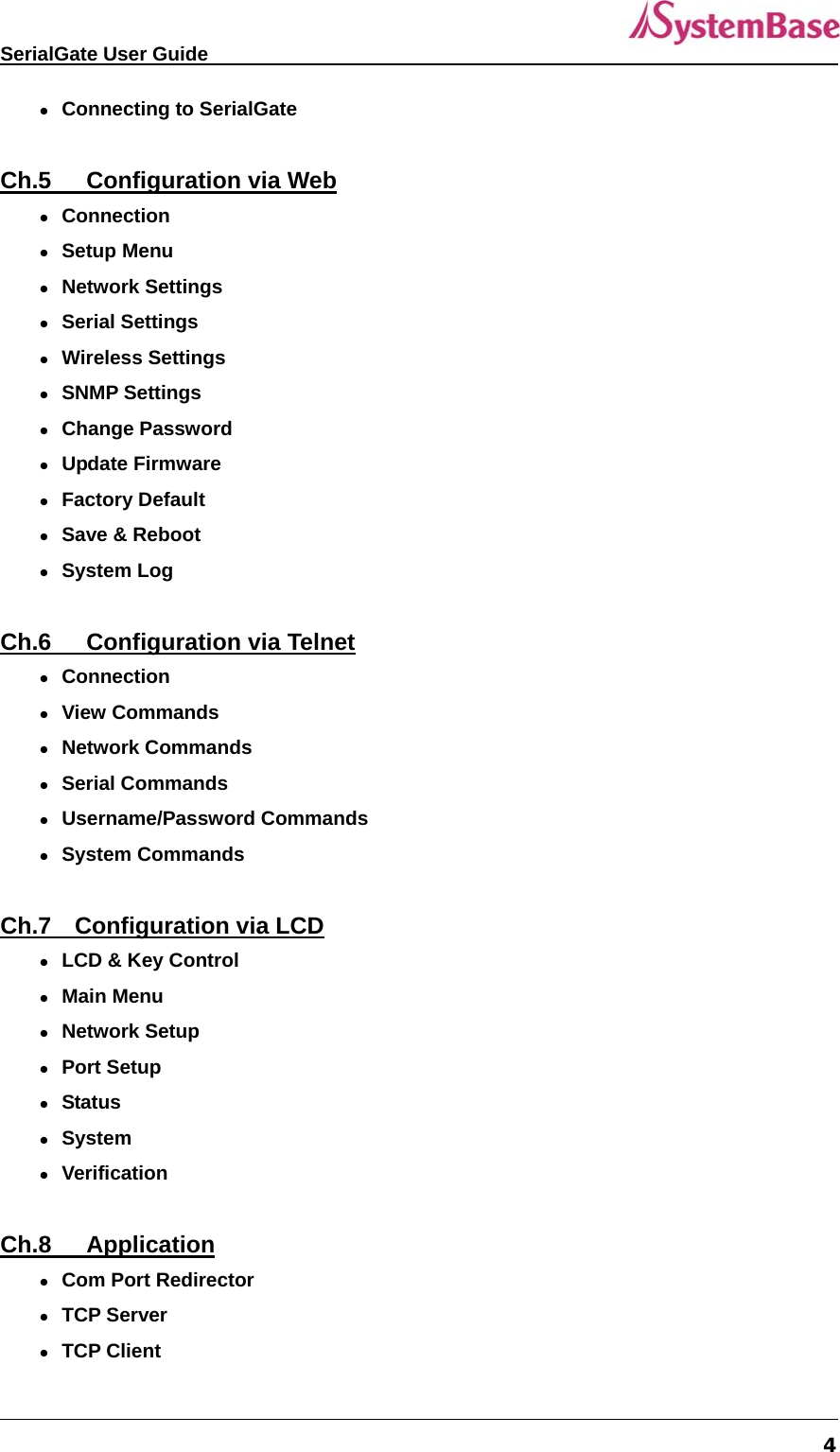
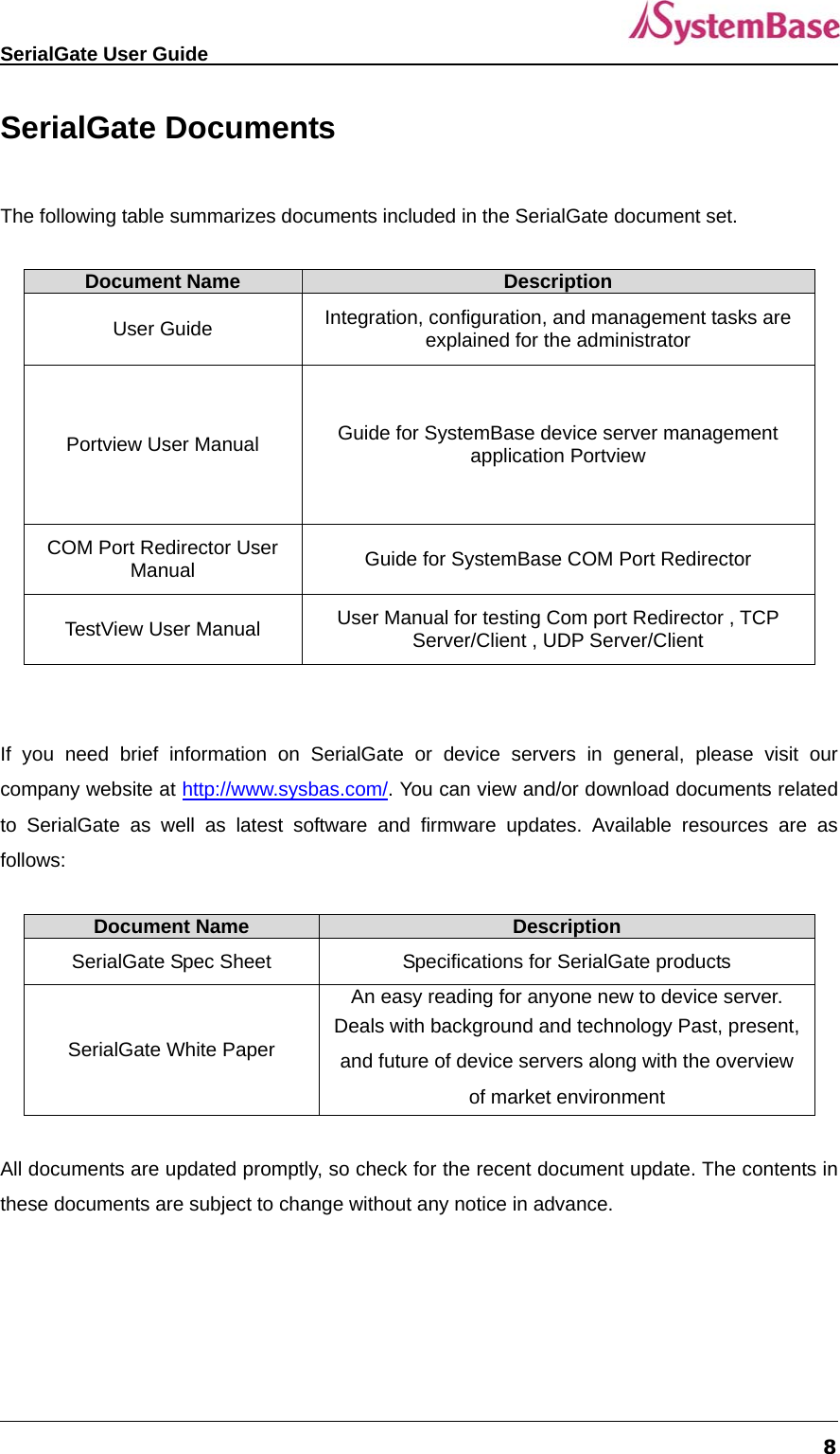
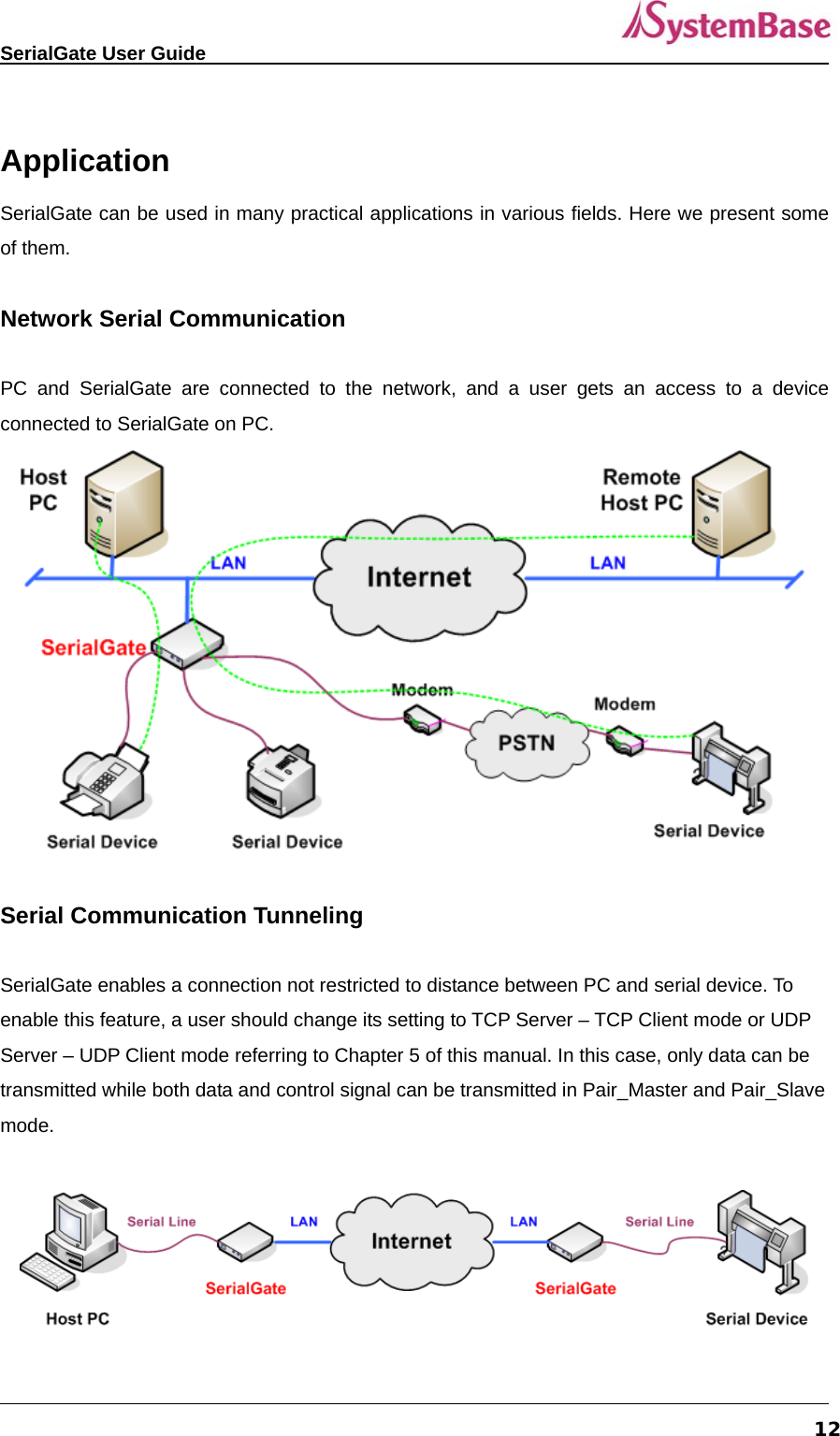
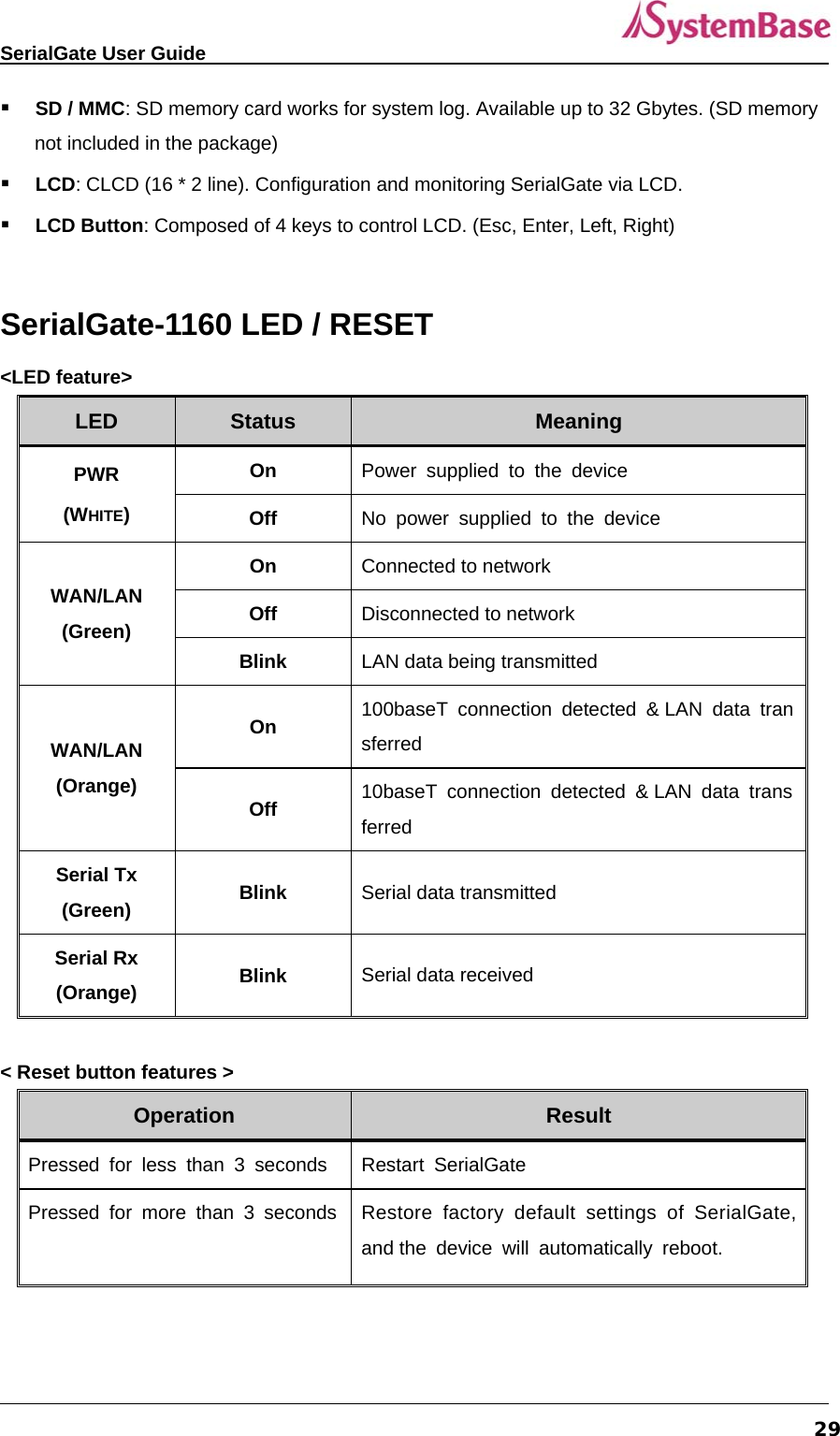
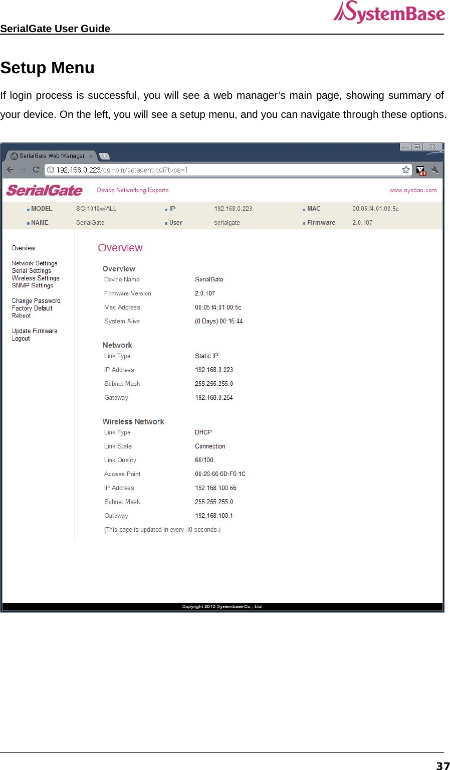
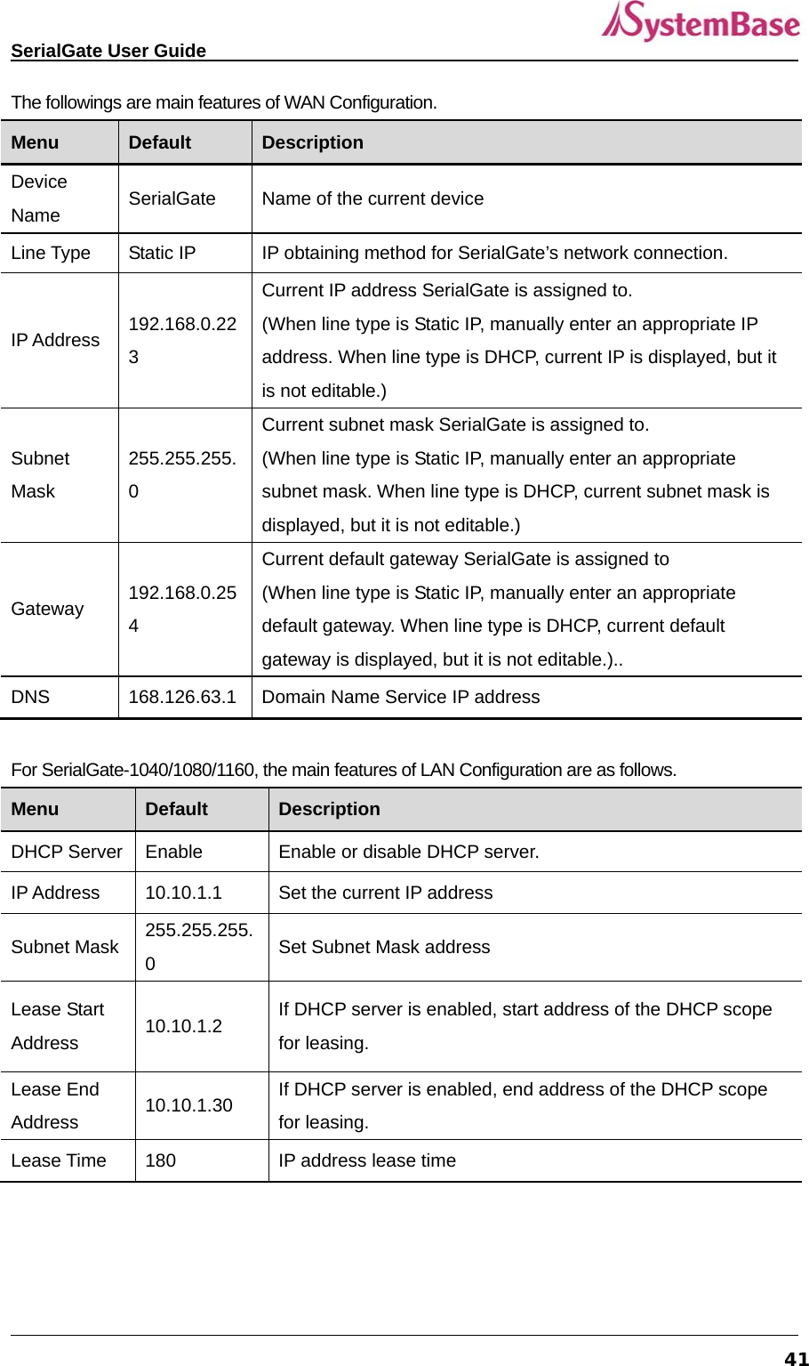
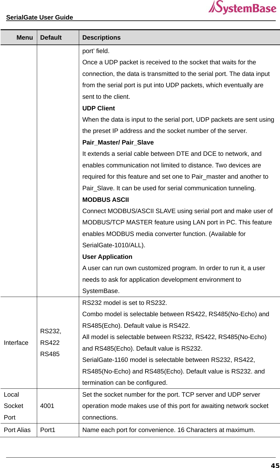
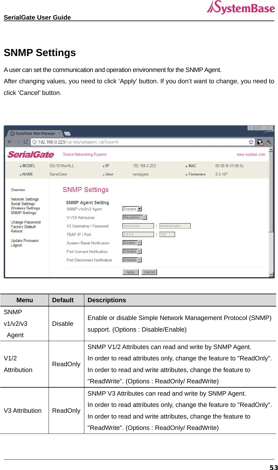
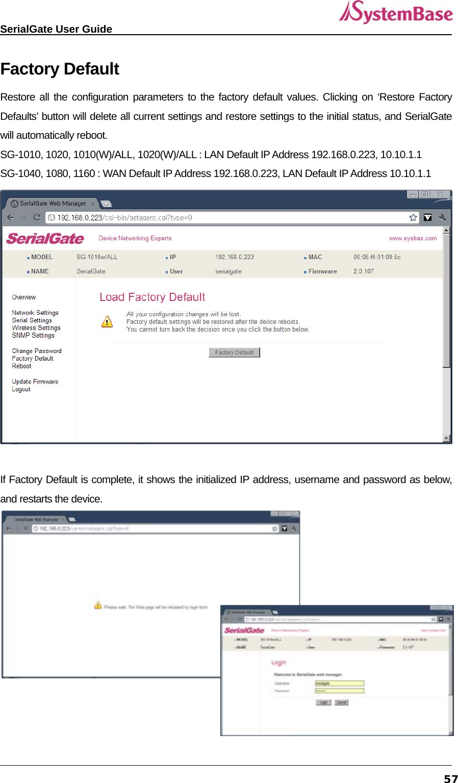
![SerialGate User Guide 63In order to read and write attributes change the feature to "ReadWrite.” (Options : ReadOnly/ ReadWrite) def v3readwrite [enable, disable] Disable SNMP V3 Attributes can read and write by SNMP Agent. In order to read attributes only change the feature to "ReadOnly.” In order to read and write attributes change the feature to "ReadWrite.” (Options : ReadOnly/ ReadWrite) def v3username [string] serialgate Configure the Username to use SNMP V3. def v3password [string] none Configure the password to use SNMP V3. def trapip [address] 0.0.0.0 Configure the server IP address which transmits the TRAP information. def trapoprt [Socket No.] 162 Configure the server Port which transmits the TRAP information. def trap_reset [enable, disable] Enable If Enable is selected, inform the "System reset info". def trap_connect [enable, disable] Disable If Enable is selected, inform the "Serial Port opened info". def trap_disconnect [enable, disable] Disable If Enable is selected, inform the "Serial Port Closed info". Serial Commands You can set the communication and operation environment for serial port. Please refer to Chapter 5 for details of each option. Commands Default Description def port x protocol [disable, com_redirect, tcp_server, Tcp_client, com Select the operation protocol to be used in serial port.](https://usermanual.wiki/SystemBase/SG-1020WALL.Manual-1/User-Guide-1802390-Page-63.png)
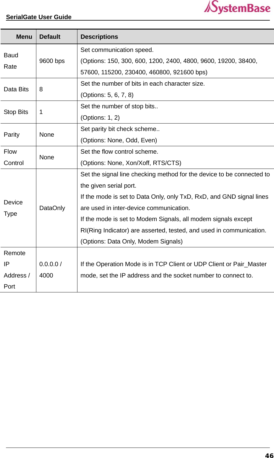
![SerialGate User Guide 64Commands Default Description tcp_broadcast, Tcp_multiplex, udp_server, udp_client, pair_master, pair_slave, modbus, user] def port x interface [rs422, ts485ne, rs485e] RS232, RS422 Configure interface of serial port. It is not available for RS232 model. Combo model can choose from RS422, RS485-No-Echo and RS485-Echo. SerialGate-1160 can choose from RS232, RS422 and RS485. def port x socket <port number> 4001 Set the socket number for the port. Com_redirect, TCP Server, TCP Multiplex, TCP Broadcast, UDP Server, Pair_Slave modes make use of this port for awaiting network socket connections. def port x name <name> Port 1 Name each port for convenience. 16 Characters at maximum def port x speed [150/300/600/1200/2400/4800/9600/19200/38400/57600/115200/230400/460800/921600] 9600bps Set communication speed. def port x data [5 / 6 / 7 / 8] 8 Set the number of bits in each character size. def port x stop [1 / 2] 1 Set the number of stop bits. def port x parity [none/odd/even] none Set parity bit check scheme. def port x flow [none/xon/rts] none Set the flow control scheme.](https://usermanual.wiki/SystemBase/SG-1020WALL.Manual-1/User-Guide-1802390-Page-64.png)
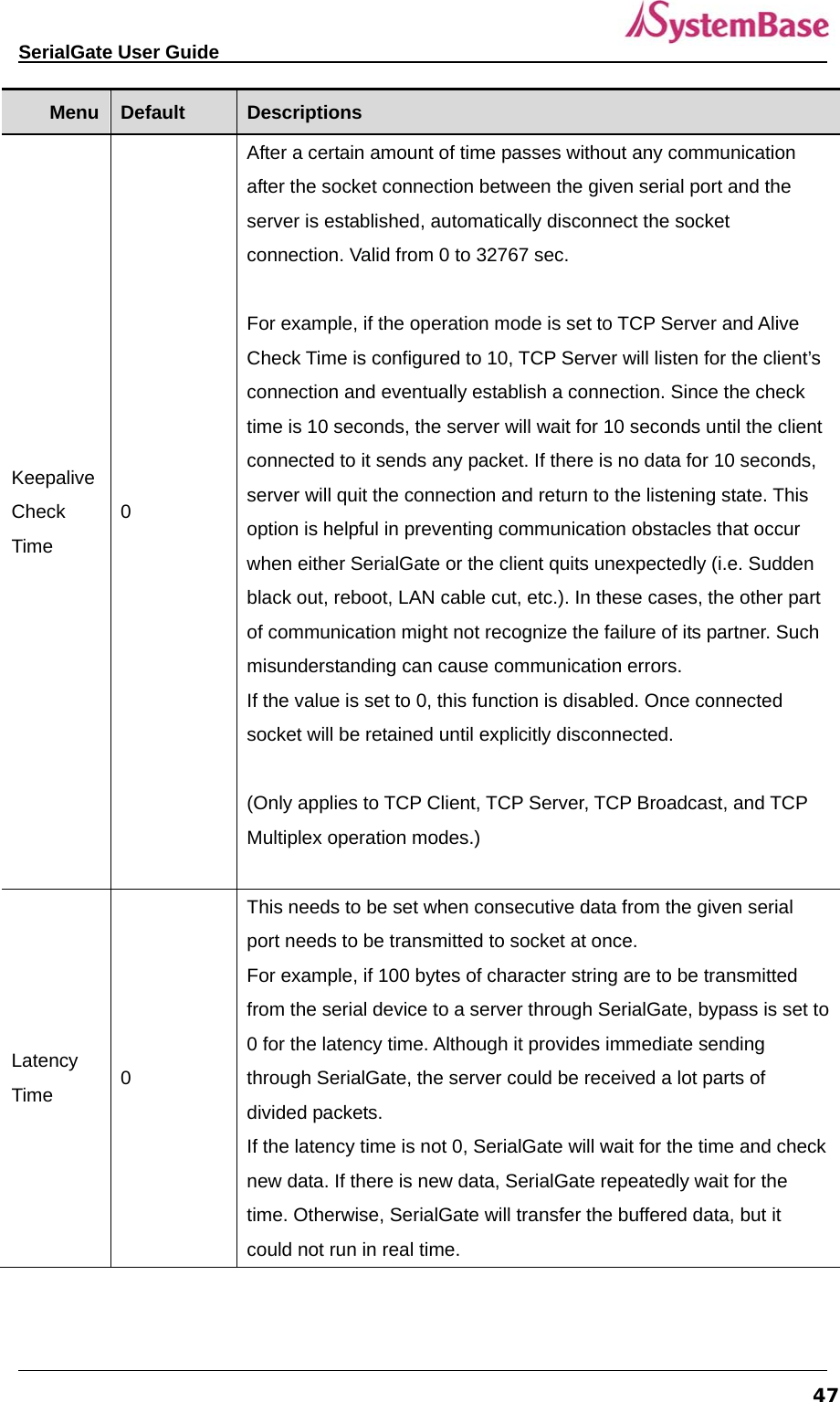
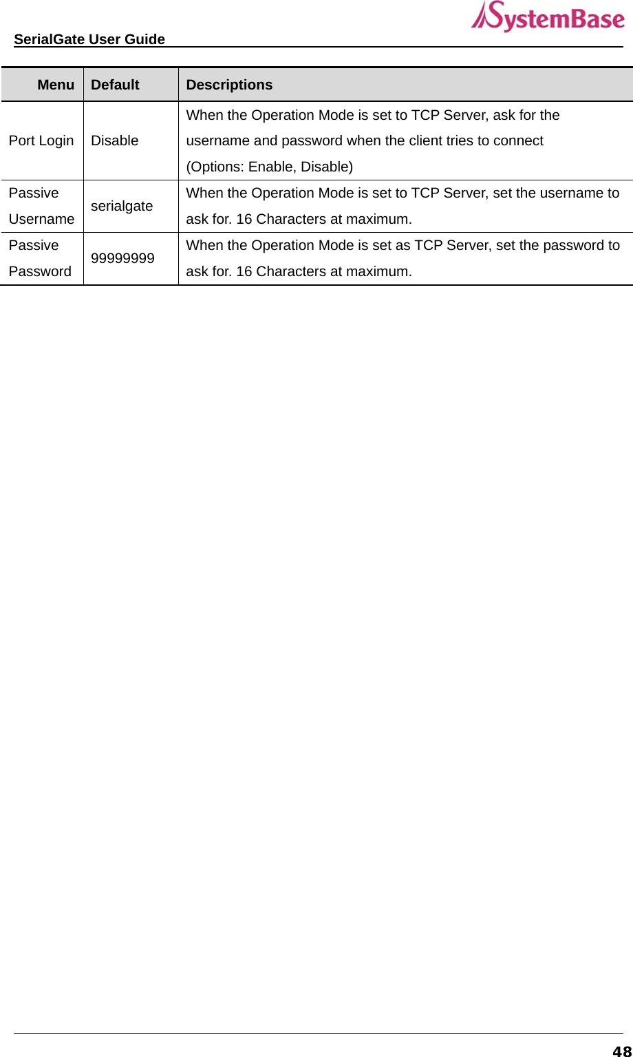
![SerialGate User Guide 65Commands Default Description def port x signal [data/modem] data Set the signal line checking method for the device to be connected to the given serial port. def port x remote <IP address> 0.0.0.0 Set IP address of the server to be connected in TCP Client, UDP Client, Pair_Master mode. def port 1 remoteport <socket number> 4000 Set the socket number to connect to when the Operation Mode is set to TCP Client or UDP Client or Pair_Master mode. def port x keepalive <0 ~ 65535> 0 After a certain amount of time passes without any communication after the socket connection between the given serial port and the server is established, automatically disconnect the socket connection. def port x latency <msec> 0 This needs to be set when consecutive data from the given serial port needs to be transmitted to socket at once. def port x txtrigger [ auto, 1, 2, 4, 8, 16, 32, 64, 96, 128] Set txtrigger of each port. def port x rxtrigger [ auto, 1, 2, 4, 8, 16, 32, 64, 96, 128] Set rxtrigger of each port. def port x fifosize <1 ~ 128> Set fifosize of each port. def port x login <Enable/Disable> Disable When the Operation Mode is set to TCP Server, ask for the username and password when the client tries to connect. def port x loginname<username> None When the Operation Mode is set to TCP Server, set the username to ask for(Max 8 bytes) def port x loginpass <password> None When the Operation Mode is set as TCP Server, set the password to ask for( Max 8 bytes) def port x termination <Enable/Disable> Disable Set termination for each port. Username/Password Commands Configure username and password for Web/Telnet/FTP.](https://usermanual.wiki/SystemBase/SG-1020WALL.Manual-1/User-Guide-1802390-Page-65.png)