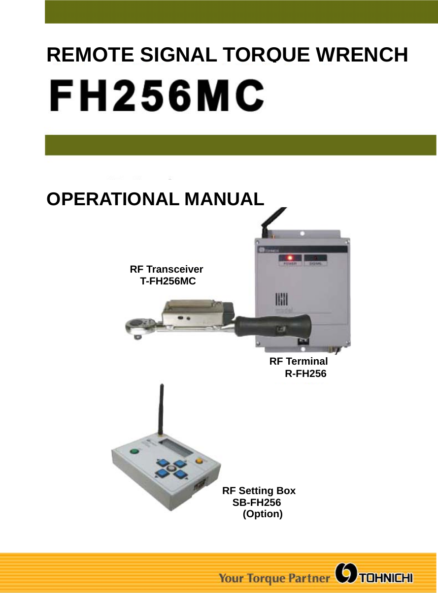
TOHNICHI MFG TFH256MC RF Transceiver User Manual FH256 User Manual FCC IC

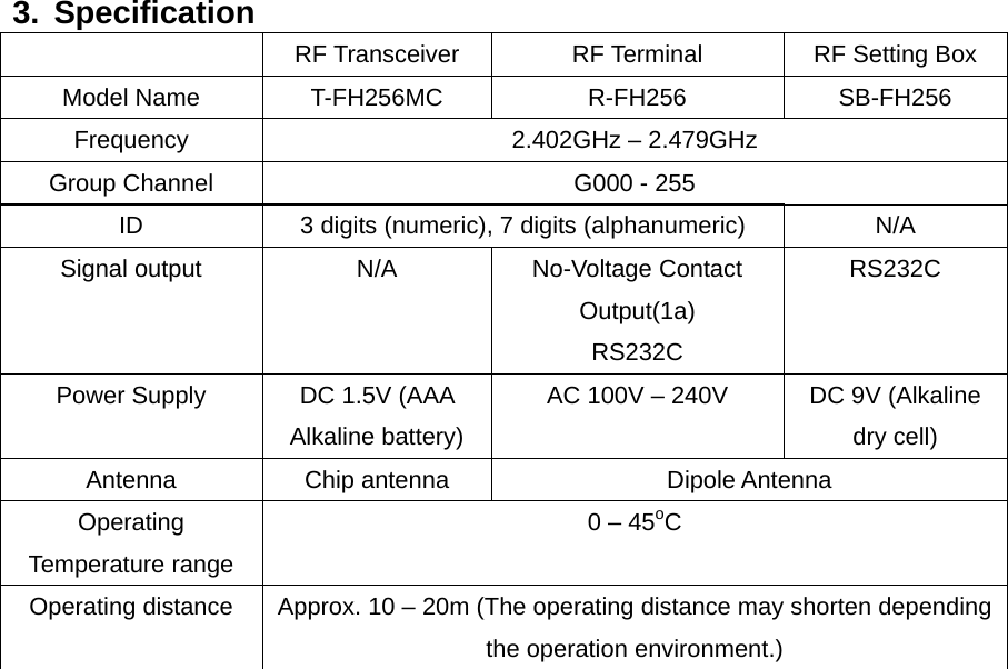
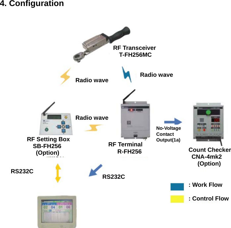
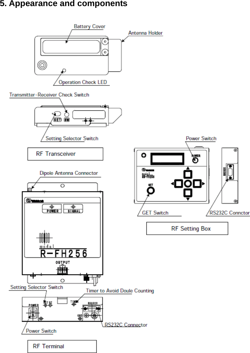
TOHNICHI MFG. CO., LTD RF Transceiver FH256 User Manual FCC IC

Manual

 REMOTE SIGNAL TORQUE WRENCH OPERATIONAL MANUALRF Transceiver   T-FH256MC   RF Terminal      R-FH256 RF Setting Box   SB-FH256     (Option)
Federal Communication Commission Declaration of Conformity (DoC) Statement   Model No: R-FH256, SB-FH256 Trade Name  TOHNICHI Responsible Party  Tohnichi America Corp. Address  677 Academy Drive, Northbrook, Illinois 60062 Telephone No  847-272-8480  This equipment has been tested and found to comply with the limits for a Class B digital device, pursuant to Part 15 of the FCC rules. These limits are designed to provide reasonable protection against harmful interference in a residential installation. This equipment generates, uses, and can radiate radio frequency energy and, if not installed and used in accordance with the instructions, may cause harmful interference to radio communications. However, there is no guarantee that interference will not occur in a particular installation. If this equipment does cause harmful interference to radio or television reception, which can be determined by turning the equipment off and on, the user is encouraged to try to correct the interference by one or more of the following measures:   • Reorient or relocate the receiving antenna.   • Increase the separation between the equipment and receiver.   • Connect the equipment into an outlet on a circuit different from that to which the receiver is connected. • Consult the dealer or an experienced radio/TV technician for help.      This device complies with Part 15 of the FCC Rules. Operation is subject to the following two conditions:  (1) This device may not cause harmful interference, and (2) This device must accept any interference received, including interference that may cause undesired operation.    Caution:  Any changes or modifications not expressly approved by the party responsible for product compliance could void the user's authority to operate the equipment.  To comply with FCC RF exposure compliance requirements, this device must not be co-located or operating in conjunction with any other antenna or transmitter.
Canada Regulatory Compliance Statement This Class B digital apparatus complies with Canadian ICES-003. Cet appareil numériqué de la classe B est conformé à la norme NMB-003 du Canada. For Customers in Canada This device complies with RSS 210 of Industry Canada (IC). Operation is subject to the following two conditions:   (1) this device may not cause interference, and (2) this device must accept any interference, including interference that may cause undesired operation of this device.  L’ utilisation de ce dispositif est autorisée seulement aux conditions suivantes : (1) il ne doit pas produire de brouillage et   (2) l’ utilisateur du dispositif doit étre prêt à accepter tout brouillage radioélectrique reçu, même si ce brouillage est susceptible de compromettre le fonctionnement du dispositif.  Exposure to radio frequency radiation  The installer of this radio equipment must ensure that the antenna is located or pointed such that it does not emit RF field in excess of Health Canada limits for the general population; consult Safety Code 6, obtainable from Health Canada’s website at www.hc-sc.gc.ca/rpb.
1. Outline This Remote Signal Type torque wrench sends the tightening completion signal to the Receiver far from the wrench through radio wave. The receiver can be connected to the Tohnichi CNA-4mk2 Count Checker to provide complete tightening assurance system to eliminate missed tightening.    2. Features ■  Antenna-less and Disconnection-less   It is easy to replace the RF Transceiver. ■  Monitoring torque wrenches by ID   It ensures traceability of Torque wrenches by ID (serial number: 7 alphanumeric  digits). ■  Only one model both RF Transceiver and RF Terminal (Minimum spare)   The group channel and torque wrench ID can be easily set and changed from the   RF Setting Box (Option). ■  Efficient working   The user with the torque wrench can know the communication status by an  answerback method.  ■  Mountable on Limit Switch(LS) Torque Wrench (T-FH256MC)   The T-FH256MC RF Transceiver can be mounted on any LS Torque Wrench with a   spacer for Limit Switch.   ■  Easy replacement of the battery for RF Transceiver only by removing the battery cover. ■  Efficient Setting by wireless technology   The group channel and torque wrench ID can be set and changed by Wireless  technology. ■  Durable Light-weigh aluminum case   The light-weight aluminum case is more durable than silicon case.   ■  World wide 2.4GHz band   It is compliant with FCC, IC and CE.
3. Specification   RF Transceiver  RF Terminal  RF Setting Box Model Name  T-FH256MC  R-FH256  SB-FH256 Frequency  2.402GHz – 2.479GHz Group Channel  G000 - 255 ID  3 digits (numeric), 7 digits (alphanumeric)  N/A Signal output  N/A  No-Voltage Contact Output(1a) RS232C RS232C Power Supply  DC 1.5V (AAA   Alkaline battery) AC 100V – 240V  DC 9V (Alkaline dry cell) Antenna Chip antenna  Dipole Antenna Operating Temperature range 0 – 45oC Operating distance  Approx. 10 – 20m (The operating distance may shorten depending the operation environment.)
4. Configuration    RF Transceiver   T-FH256MC   RF Terminal      R-FH256 RF Setting Box   SB-FH256    (Option)  Count Checker  CNA-4mk2    (Option) Radio wave Radio wave Radio wave RS232C RS232C No-Voltage Contact Output(1a)  : Work Flow  : Control Flow
 5. Appearance and components
6. Operation 6-1 Precaution ①  Handle the torque wrench with care. ②  Read the Operation Manual before operation. ③ In case that the an adjustable screw of Preset/Pre-lock type wrench is changed, the switching mechanism may not work well. Please contact a Tohnichi authorized distributor or Tohnichi office for replacing a Stud of the torque wrench.    6-2 Replacing RF Transceiver ①  Loosen two screws of the transceiver and remove it. ②  Install the transceiver, and tighten the screws. (Tightening torque T=270cN・m) Note: Stud, which comes from wrench, should not be between place spring and the Battery case when installing the Transceiver.    6-3 Setting the Time to Avoid Double Counting   ①  The Timer is set to 1 second when delivered. ②  To change the time setting, return the variable resistance (VR2) on the Receiver board. (Refer to “5. Appearance and components”.) ③  The time can be set between 0.2 sec and 2.2 sec.  6-4 Battery Check ①  Push the Transmitter-Receiver Check Switch.   ② If the Operation Check LED is Green, the battery should be serviceable. If it is red, replace the battery. Refer to “6-5 Replacing Battery for Transmitter”.    6-5 Replacing Battery for RF Transceiver ①  Loosen two screws of the battery cover and remove it. ②  Remove the empty Battery, and insert a new one. ③  Always use an AAA Alkaline Battery. ④ Install the battery cover, and tighten the screws by a torque driver. (Tightening torque T=63cN・m)
6-6 Channel, Group and ID Setting 6-6-1 RF Transceiver Setting ① Set the Setting Selector Switch on the RF Transceiver to “Left” side. The Operation Check LED turns red and is flashing.   ②  Push the GET Switch on the RF Setting Box. The current setting appears on the upper display.  ③  Set up a channel group, a criterion code and ID (3 digits).   ④  Push the SET Switch on the RF Setting Box. ⑤  The Operation Check LED turns green and lights up around 1 second. After that, it turns red and starts to flash.   ⑥  After confirmed the setting, set the Setting Selector Switch to “Right” side.   6-6-2 RF Terminal Setting ① Set the Setting Selector Switch on the RF Terminal to “Left” side. The SIGNAL LED is flashing.  ②  Push the GET Switch on the RF Setting Box. The current setting appears on the upper display.  ③  Set up a channel group, a criterion code and ID (3 digits).   ④  Push the SET Switch on the RF Setting Box. ⑤  The buzzer of the RF Terminal starts if the buzzer ON/OFF switch is set to ON. ⑥  After confirmed the setting, set the Setting Selector Switch to “Right” side.

Navigation menu