TRIMBLE EUROPE 110610 GSM/GPRS/UMTS/HSPA Module User Manual SP90MUG
TRIMBLE EUROPE BV GSM/GPRS/UMTS/HSPA Module SP90MUG
Contents
- 1. Host user manual 1_SP90M_UG_B_Draft2_en-v1a.pdf
- 2. Host user manual 1_SP90M_UG_B_Draft2_en-v1b.pdf
- 3. Host user manual 2_SP90M_UG_B_Draft2_en-v2.pdf
- 4. User guide_SP85_UG_A_en-part2_Part1
- 5. User guide_SP85_UG_A_en-part2_Part2
- 6. User guide_SP85_UG_A_en-part2_Part3
- 7. User guide_SP85_UG_A_en-part2_Part4
Host user manual 1_SP90M_UG_B_Draft2_en-v1a.pdf
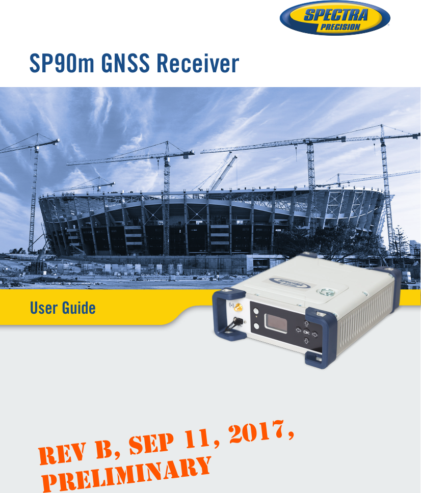
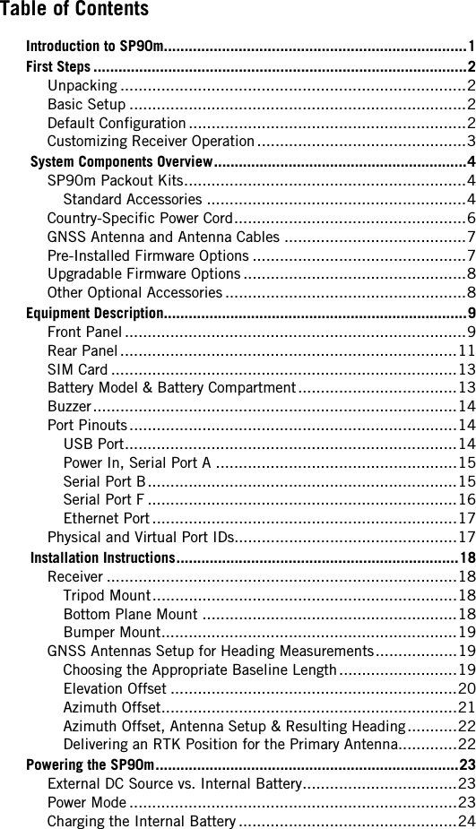
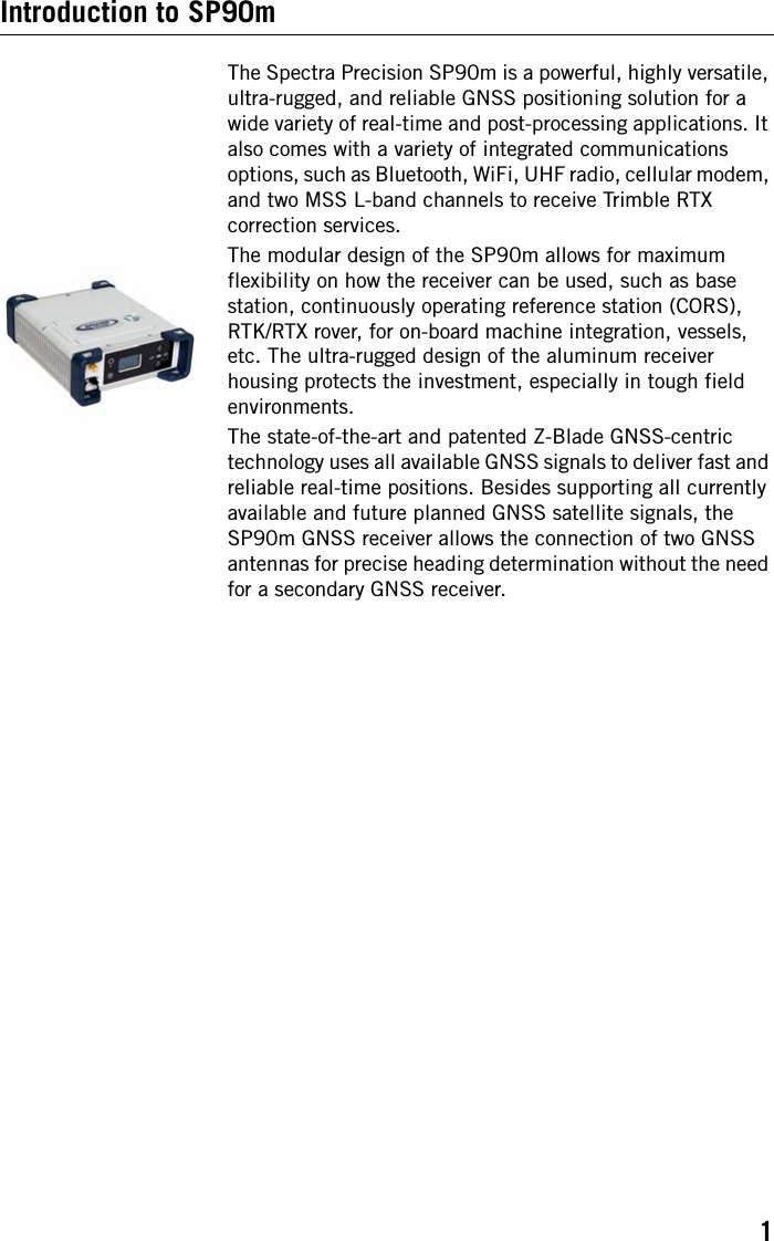
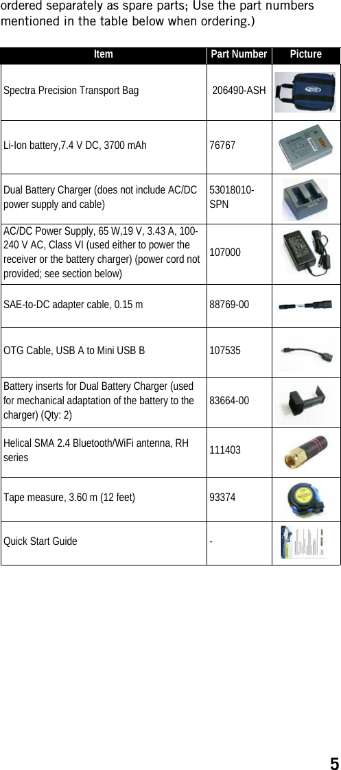
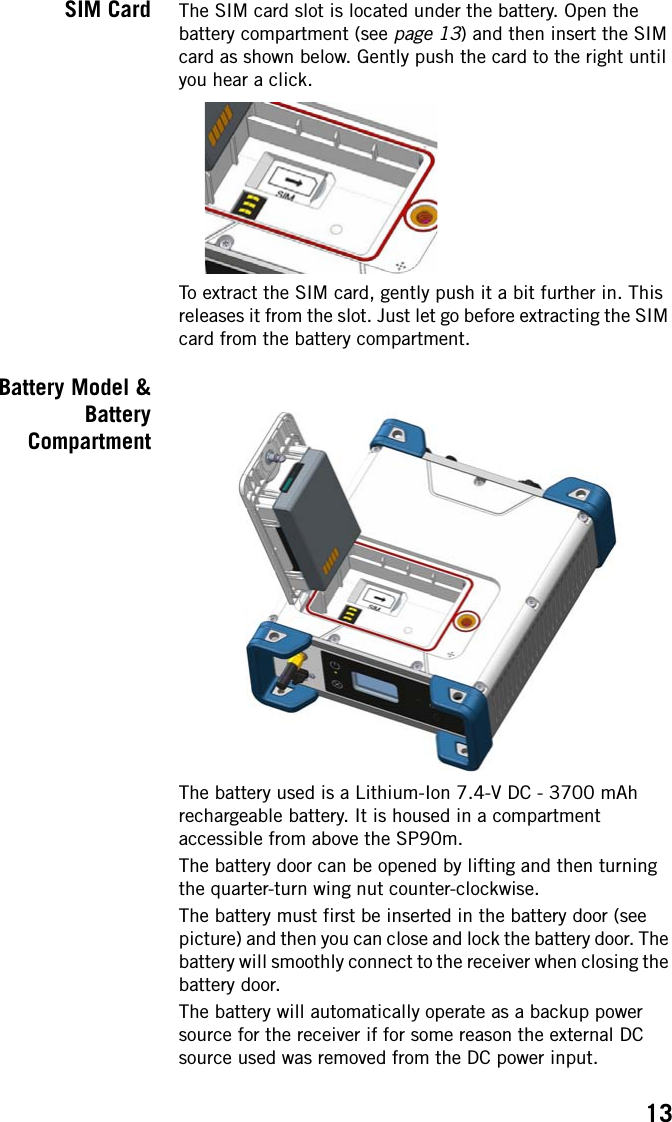
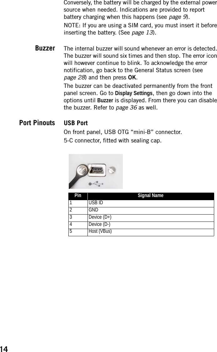
![9Equipment DescriptionFront Panel•[1]: External Bluetooth/WiFi antenna connector. A coaxial female connector (reverse SMA type) allowing you to connect a Bluetooth or WiFi antenna for wireless communication with a field terminal or any other device.•[2]: Power button.To turn on the receiver, press the Power button for about two seconds until the power LED [5] turns solid green, then release the button. The receiver will automatically complete its initialization phase before it starts operating normally.To turn off the receiver, press the same Power button for about two seconds. The Power LED will blink green until the receiver gets turned off.•[3]: Display screen. The display consists of a 128 x 64-pixel, 1.5-inch monochrome blue-gray OLED screen.Used in conjunction with the direction keys, the OK and Escape keys, the display screen allows you to view and edit different pages of information. See Receiver User Interface on page 26 for a detailed description of the information available from this screen.After a few seconds of keypad inactivity, screen luminosity is turned off.•[4]: Keypad including four direction keys and a central OK key. See details on page 26.[1][6] [7] [8][8][2] [5] [3] [4]](https://usermanual.wiki/TRIMBLE-EUROPE/110610.Host-user-manual-1-SP90M-UG-B-Draft2-en-v1a-pdf/User-Guide-3573047-Page-17.png)
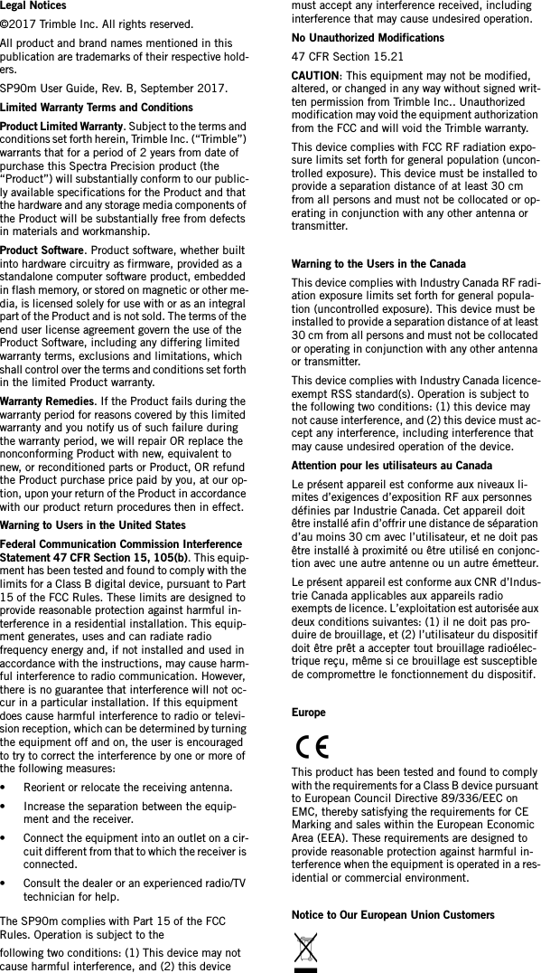
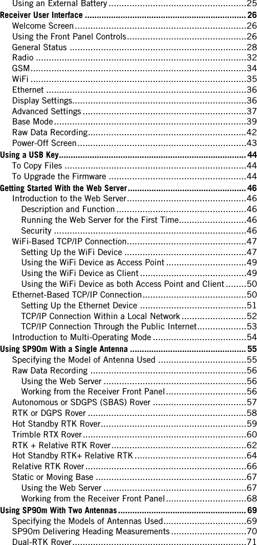
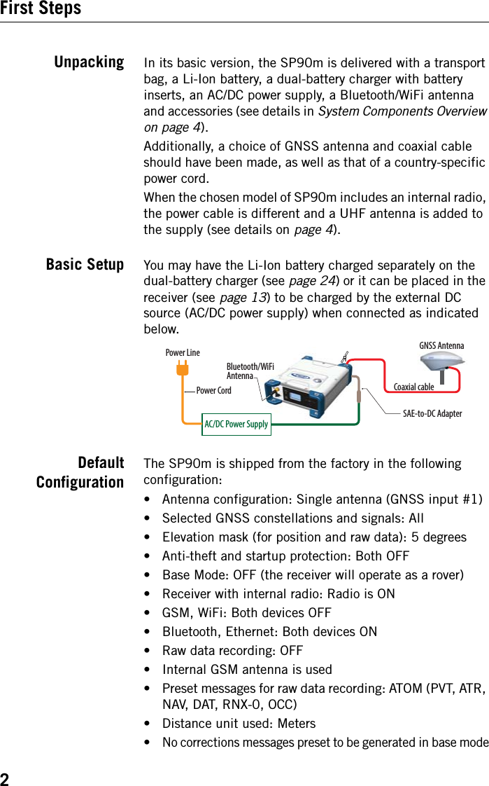
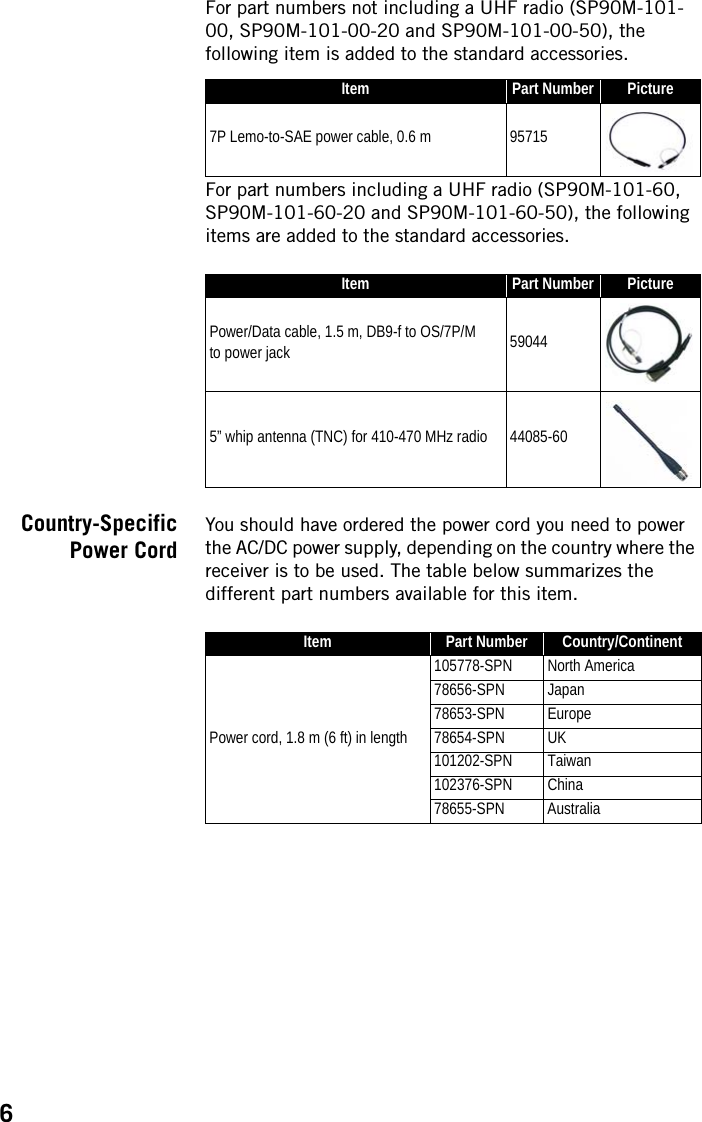
![10•[5]: Power LED. Possible states:•[6]: USB OTG mini connector (port U or M).This is a five-contact connector. Depending on how it is configured, the USB port can be connected to:1. A USB host, such as a USB key (mass storage device), using cable P/N 107535.2. A USB device (port U), allowing USB serial communication using a standard USB cable (not provided).This port is used typically for downloading/deleting files using SP File Manager, (in this case the receiver is seen as a disk) or upgrading firmware/warranty date using SP Loader.The first time you connect the SP90m to a computer through a USB connection, the required driver will automatically be installed on the computer. If however the installed driver does not work, you may replace it with one of the two drivers posted on the Spectra Precision website:State MeaningOffSP90m is off and no external power source is connected to the DC power input (but the inter-nal battery may be present).Solid greenSP90m is on (initializing or steady state), being powered from an external power source. If the internal battery is present, battery charging from the external source will take place if needed (see battery icon on General Status screen).Solid green, but with 0.5-s “off” time every 2 secSP90m is on (initializing or steady state), being powered from the internal battery. No external power source is applied.Blinking greenSP90m is running a 5-second power-off sequence following a long press on the Power button (regardless of the power source used).Solid redSP90m is off and an external power source is connected to the receiver. The internal battery may be missing or present. If it is present, that means the battery is fully charged.Blinking redSP90m is off and an external power source is connected to the receiver. An internal battery is present and being charged from the external power source.](https://usermanual.wiki/TRIMBLE-EUROPE/110610.Host-user-manual-1-SP90M-UG-B-Draft2-en-v1a-pdf/User-Guide-3573047-Page-18.png)
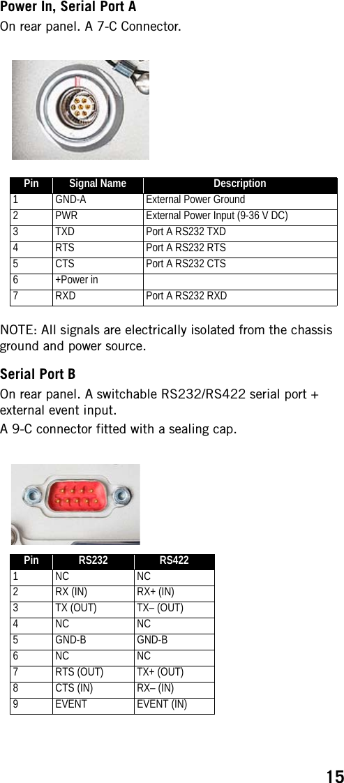
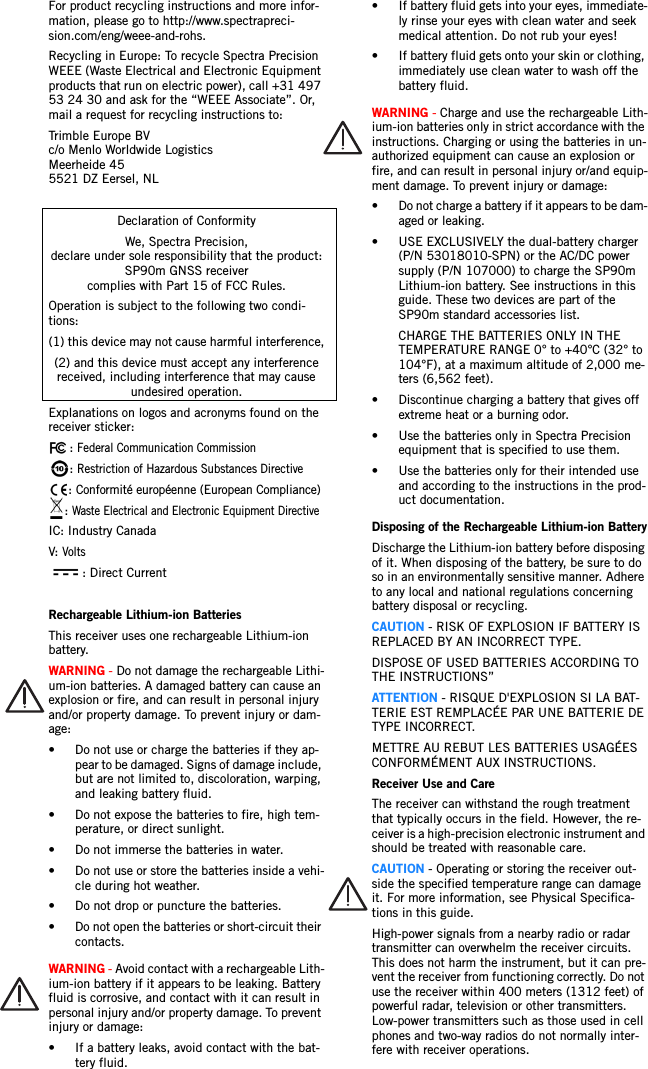
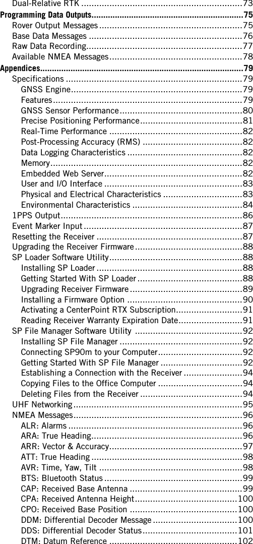
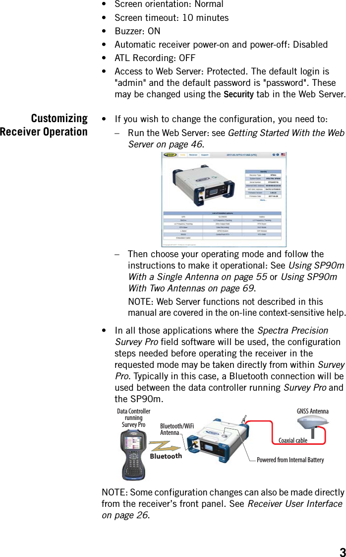
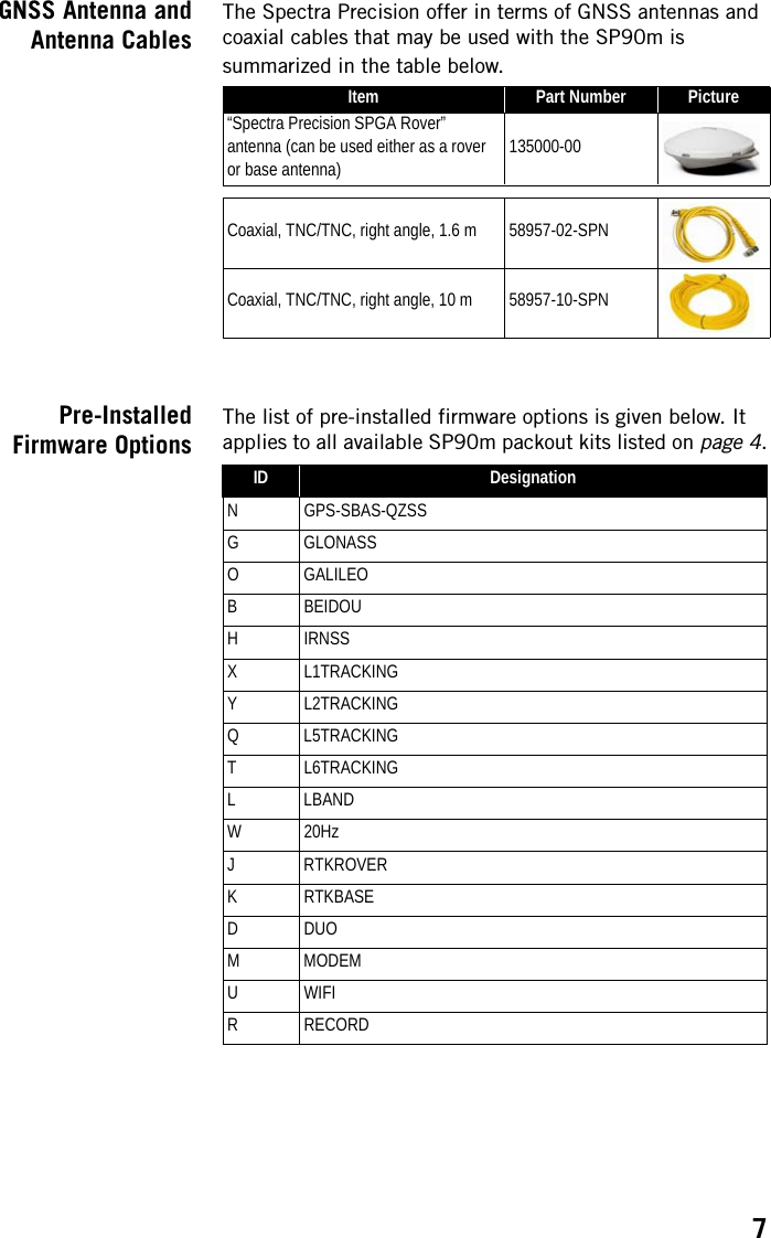
![11http://www.spectraprecision.com/eng/sp90m.html#.WUkG_NxLep0USB driver for 64-bit OS: SpectraPrecisionUSBSerialSetup_x64.exe fileUSB driver for 32-bit OS: SpectraPrecisionUSBSerialSetup_x86.exe fileDouble-click on the downloaded file to install the driver.•[7]: Escape button. See Using the Front Panel Controls on page 26.•[8]: Bumpers (x2).Rear Panel•[8]: Bumpers (x2).•[9]: GNSS input #1. A TNC coaxial female connector allowing you to connect the first GNSS antenna to the receiver via a coaxial cable.•[10]: GNSS input #2. A TNC coaxial female connector allowing you to connect the second GNSS antenna to the receiver via a coaxial cable.•[11]: External GSM antenna (optional). A coaxial female connector (SMA type) allowing you to connect an external cellular antenna.The SP90m having a built-in GSM antenna, no external GSM antenna is usually required. In case of adverse reception conditions however (e.g. SP90m mounted in a rack), an external antenna can advantageously be used for better reception. Run the Web Server (Receiver> Network> Modem> Modem Antenna) to choose which of the internal or external antenna should be used.The SP90m uses a GSM antenna when it sends or receives RTK or differential corrections via its GSM modem.•[12]: UHF radio connector. A TNC coaxial female connector allowing you to connect a radio whip antenna. This connector is available only if the SP90m has been fitted with an internal radio.Warning! Do not confuse this coaxial connector with the GNSS inputs. Connecting a GNSS antenna to the UHF [9][13] [17][16][14] [15][10] [11] [12][8] [8]](https://usermanual.wiki/TRIMBLE-EUROPE/110610.Host-user-manual-1-SP90M-UG-B-Draft2-en-v1a-pdf/User-Guide-3573047-Page-19.png)
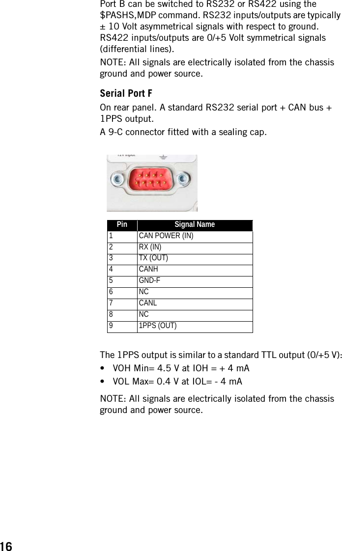
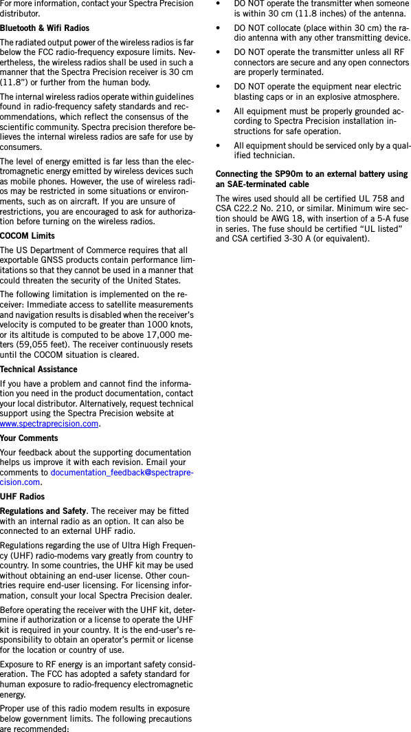
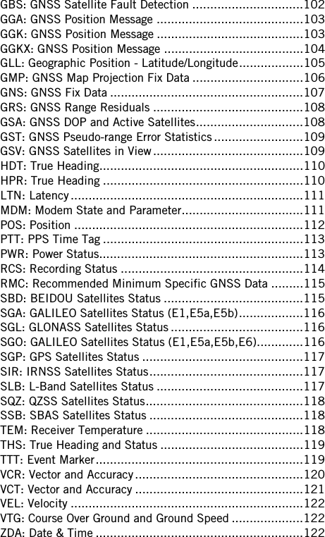
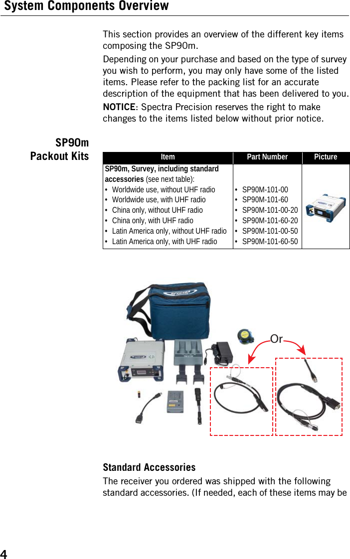
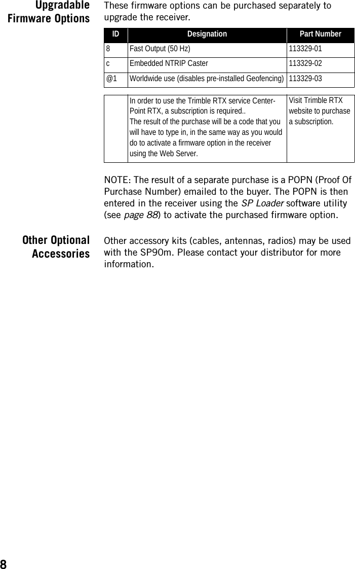
![12connector might damage it if the embedded UHF transmitter is used (however the transmitter will not be transmitting until there are enough GNSS satellites tracked and used).•[13]: DC Power input and serial port A (RS232). A seven-contact, female connector allowing the SP90m to be powered from either the provided AC adapter (connect the cable extension between SP90m and the end of the AC adapter output cable), or an external 9- to 36-V DC power source through cable P/N 730477 (e.g. base setup using an external radio transmitter).•[14]: Ethernet connector. A 7-contact female connector (RJ45) allowing you to connect the SP90m to a local network (LAN). Through this connection, you may remotely control and monitor SP90m operation from any computer connected to the Internet. Data may also flow through this connection, in the same way as through a serial port.•[15]: RS232 serial port F, a SubD, nine-contact, male connector. The PPS signal and the not operational yet CAN bus are also available on this connector.•[16]: Earth terminal. A screw terminal for connecting the receiver chassis to Earth.Electric Isolation: All signals available on the following connectors are optically isolated from the receiver’s internal circuitry and chassis ground, as well as from each other: • Serial ports A, B and F (including DC power output voltage on port A)• Ethernet port•USB port•[17]: Switchable RS232/RS422 serial data port B (default is RS232), a SubD, nine-contact, male connector. The External Event input is also present on this connector.](https://usermanual.wiki/TRIMBLE-EUROPE/110610.Host-user-manual-1-SP90M-UG-B-Draft2-en-v1a-pdf/User-Guide-3573047-Page-20.png)