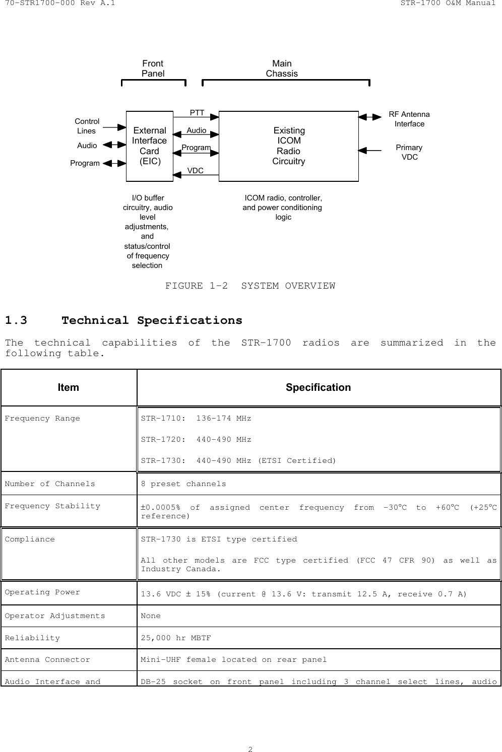
Tactical Electronics IC-F521 VHF TRANSCEIVER User Manual 70 STR1700 00 O M Rev A1

Tactical Electronics Corporation VHF TRANSCEIVER 70 STR1700 00 O M Rev A1

USERS MANUAL

 SRI Summation Research Inc   STR-1700 UHF/VHF Land Mobile Radio Operations and Maintenance Manual DevelopmentResear ch Meeting the 21st Century Challenges - with – Advanced Technology Solutions  Prepared by: Summation Research Inc – Melbourne, FL  Drawing Number: 70-STR1700-00 Revision A.1 October, 2004  This document contains information proprietary and confidential to SRI.  Transmittal, receipt, or possession of this document does not express, license, or imply any rights to use, design, or manufacture from this information.  No reproduction, publication, or disclosure of this information, in whole or in part, shall be made without prior written authorization from an officer of SRI.  SRI • 751 NORTH DRIVE • MELBOURNE, FLORIDA  32934  (321) 254-2580 • FAX (321) 254-2492 Internet : www.summationresearch.com • Email : info@summationresearch.com  © Copyright 2003, SRI Printed in U.S.A.
70-STR1700-000 Rev A.1  STR-1700 O&M Manual   i  SUMMATION RESEARCH, INC.   LIMITED WARRANTY   Summation Research, Inc. (herein called SRI) warrants that the equipment’s of its manufacture as identified and described within this manual shall, at the time of shipment to the original purchaser, be free from defects in material and workmanship.  This warranty applies only to equipment installed, operated, and maintained in accordance with SRI recommendations.  This warranty does not apply where SRI determines that installation, repair, alteration, or accidents have caused any claimed defect, or that excessive deterioration due to environmental contamination has occurred.   SRI’s obligation under this warranty is limited to repairing, or replacing, exclusive of cost of installation and labor charges, any part that SRI determines to be defective, provided that such part is received at SRI’s principal office, freight prepaid.  All equipment's must receive prior approval for return to SRI for warranty repair, and must be sent prepaid.  If they are returned collect, they will not be accepted.   This warranty is subject to any existing conditions of supply that may directly affect SRI’s ability to obtain materials or manufacture replacement parts.   SRI makes no warranty that the equipment shall be merchantable or fit for any particular purpose; nor does SRI make other warranties, express or implied, by operation of law or otherwise, except such as are expressly set forth herein.  SRI shall not be liable to buyer, or to any third persons for any incidental, consequential, special or contingent damages for breach of any warranty.   All specifications within this document are subject to change without prior written notice.  0
70-STR1700-000 Rev A.1  STR-1700 O&M Manual   ii   20 RF Exposure Statement  The radio generates RF electromagnetic energy during transmit mode. This radio is designed for and classified as “Occupational Use Only”, meaning it must be used only during the course of employment by individuals aware of the hazards, and the ways to minimize such hazards. This radio is NOT intended for use by the “General Population” in an uncontrolled environment.  • For compliance with FCC and Industry Canada RF Exposure Requirements, the transmitter antenna installation shall comply with the following two conditions:  1.  The transmitter antenna gain shall not exceed a limit necessary for the application. 2.  The transmitter antenna is required to be located outside of a vehicle and kept at a separation distance of  45 centimeters or more between the transmitter antenna of this device and persons during operation.  To ensure that your exposure to RF electromagnetic energy is within the FCC allowable limits for occupational use, always adhere to the following guidelines: •DO NOT operate the radio without a proper antenna attached, as this may damage the radio and may also cause you to exceed FCC RF exposure limits. A proper antenna is the antenna supplied with this radio by the manufacturer or an antenna specifically required to meet application requirements. •DO NOT transmit for more than 50% of total radio use time(“50% duty cycle”). Transmitting more than 50% of the time can cause FCC RF exposure compliance requirements to be exceeded.   Electromagnetic Interference/Compatibility  During transmissions, the radio generates RF energy that can possibly cause interference with other devices or systems. To avoid such interference, turn off the radio in areas where signs are posted to do so. DO NOT operate the transmitter in areas that are sensitive to electromagnetic radiation such as hospitals, aircraft, and blasting sites.
70-STR1700-000 Rev A.1  STR-1700 O&M Manual   iii   RECORD OF CHANGES   Dates of issue for original and each revision of this document are:    Revision A  October 2004  Initial Production Release   Revision A.1  January 2005  Added FCC RF Exposure Statement          Corrected VHF channel spacing         specification      LIST OF EFFECTIVE PAGES  Number of pages in this publication (excluding schematics, assembly and mechanical diagrams in appendices) is as follows:     i - vi  Table of Contents/List of Figures/List of Tables    1 - 19  Document Main Text   NOTE: On partial document updates, insert latest changed pages and destroy superseded pages.  Revision changes are indicated by horizontal bars on the right hand side of the page for any text modifications, or by double lines around modified cells within tables.
70-STR1700-000 Rev A.1  STR-1700 O&M Manual  TABLE OF CONTENTS    iv  SECTION 1 INTRODUCTION ......................................... 1 1.1 Scope .................................................................1 1.2 Product Description ...................................................1 1.3 Technical Specifications ..............................................2 1.4 Reference Documentation ...............................................4 SECTION 2 RECEIVING, INSPECTION AND INSTALLATION ............... 5 2.1  Unloading and Unpacking ...............................................5 2.2 Receiving Documentation ...............................................5 2.3  Installation and Connection Requirements ..............................5 2.4  Connector Descriptions and Signal Definitions .........................5 2.4.1 Primary Power......................................................5 2.4.2 Antenna............................................................6 2.4.3 Audio/Control......................................................6 SECTION 3 OPERATION ............................................ 9 3.1  Minimum System Requirements ...........................................9 3.2 Software Installation .................................................9 3.3  Conventions and File Structures .......................................9 3.4 Getting Started ......................................................10 3.4.1 Radio Interconnect................................................10 3.4.2 Power-on Sequence.................................................10 3.4.3  Reading the Radio Configuration...................................11 3.5  Altering the Radio Configuration .....................................12 3.5.1  Changing Individual Channel Settings..............................12 3.5.2  Setting/Changing Model Defaults...................................12 3.5.3  Saving/Restoring Channel Parameters...............................13 3.6 Radio Operation ......................................................13 SECTION 4 MAINTENANCE ......................................... 14 4.1 Maintenance Concept ..................................................14 4.2  Preventive Maintenance Requirements ..................................14 4.2.1 Inspection........................................................14 4.2.2 Cleaning..........................................................15 APPENDIX A  MECHANICAL DRAWING ................................. 16
70-STR1700-000 Rev A.1  STR-1700 O&M Manual  TABLE OF CONTENTS (Continued)     v  APPENDIX B  SCHEMATICS ......................................... 17 APPENDIX C  ASSEMBLY DRAWINGS .................................. 18
70-STR1700-000 Rev A.1  STR-1700 O&M Manual  LIST OF FIGURES   vi  FIGURE 1-1  Product Comparison ...............................................1 FIGURE 1-2  System Overview ..................................................2 FIGURE 3-1  Radio to PC Interconnect Configuration ..........................10 FIGURE 3-2  Control Software Initial Screen .................................11
70-STR1700-000 Rev A.1  STR-1700 O&M Manual  LIST OF TABLES   vii  TABLE 2-1 Primary Power Connector Characteristics............................6 TABLE 2-2 Antenna Port Connector Characteristics.............................6 TABLE 2-3 Audio/Control Connector Characteristics............................6 TABLE 2-4 Audio/Control Connector Pin Assignments............................7 TABLE 2-5 Channel Selection Control Settings.................................8
70-STR1700-000 Rev A.1  STR-1700 O&M Manual  1  SECTION 1  INTRODUCTION  The STR-1700 series of UHF/VHF radio product represents a state-of-the-art communications line providing half-duplex audio to radio frequency (RF) transmit and receive functions.  Consisting of multiple models, the series provides FM transceiver functions in the 140 to 162 MHz and 400 to 512 MHz frequency bands.  The design has been tailored towards narrowband data telemetry applications requiring fast transmit/receive response times with compact size and high reliability.  1.1 Scope   This manual describes the Summation Research, Incorporated STR-1700 series of  Land Mobile Radios.  The manual includes specifications, design description, installation, and operation instructions along with routine maintenance requirements for the STR-1700.  1.2  Product Description   The STR-1700 is a modified version of a standard UHF/VHF radio product produced by ICOM.  The VHF versions of the radio incorporate the ICOM IC-F521 transceiver while the UHF version incorporate the IC-F610 or IC-F621.  In order to make the product more applicable for data communications functions, the STR-1700 product line incorporates a custom front panel as depicted in the following picture.      IC-F521/F610/F621  STR-1700  FIGURE 1-1  PRODUCT COMPARISON  The custom front panel replaces the normal operator oriented local status/control interface and audio interface connector with a single DB-25 connector targeted for computer control.  The DB-25 provides both the audio interface and a strapping capability for frequency select.  This feature is incorporated via a custom printed circuit board (PCB) located within the STR-1700 front panel known as an External Interface Card (EIC).  The following figure depicts this implementation.
70-STR1700-000 Rev A.1  STR-1700 O&M Manual  2    ExistingICOMRadioCircuitryExternalInterfaceCard(EIC)AudioVDCRF AntennaInterfacePrimaryVDCFrontPanelMainChassisProgramAudioControlLinesProgramI/O buffercircuitry, audioleveladjustments,andstatus/controlof frequencyselectionICOM radio, controller,and power conditioninglogicPTT FIGURE 1-2  SYSTEM OVERVIEW  1.3  Technical Specifications   The technical capabilities of the STR-1700 radios are summarized in the following table.     Item   Specification Frequency Range  STR-1710:  136-174 MHz  STR-1720:  440-490 MHz  STR-1730:  440-490 MHz (ETSI Certified) Number of Channels  8 preset channels Frequency Stability  ±0.0005% of assigned center frequency from -30°C to +60°C (+25°C reference) Compliance  STR-1730 is ETSI type certified All other models are FCC type certified (FCC 47 CFR 90) as well as Industry Canada.  Operating Power  13.6 VDC ± 15% (current @ 13.6 V: transmit 12.5 A, receive 0.7 A) Operator Adjustments  None Reliability  25,000 hr MBTF Antenna Connector  Mini-UHF female located on rear panel Audio Interface and  DB-25 socket on front panel including 3 channel select lines, audio
70-STR1700-000 Rev A.1  STR-1700 O&M Manual  3   Item   Specification Control Connector  in/out, push-to-talk, and programming interface. Power Connector  AMP High Power DC Channel Spacing  UHF: Selectable to either 25 KHz or 12.5 KHz channel spacing. VHF: Selectable to either 30 KHz or 15 KHz channel spacing. RF Output Power  Selectable between 5 and 30 watts (±2%) into a VSWR of 2:1 or better. (ETSI models limited to 25 watts max.)   Output Impedance  50 ohms, nominal Output Protection  Operating into a 10:1 VSWR of any phase angle will not damage the transceiver. Modulation  FM with a rated deviation of +/- 5 KHz for 25 KHz channel spacing and +/- 2.5 KHz for 12.5 KHz channel spacing. Modulation Sensitivity  An 80 mvolt RMS audio input signal produces 60% of rated deviation. Turn-On Time  Within 20 msec (UHF models) or 40 msec (VHF model) of application of the keying signal, the transceiver reaches 90% of programmed output power and is capable of transmitting an on frequency signal with a SINAD of 30 dB or greater. Spurious and Harmonic Output  -70 dB below rated power Audio Input Impedance  10 K Ohm ±20% Transmit Audio Frequency Response  Flat response over the 300-3000 Hz range.  No pre-emphasis. Minimum Duty Cycle  Capable of 30 seconds transmit keying or 25% continuous duty cycle. Output S/N Ratio  30 dB minimum fully modulated Spurious Leakage  -57 dBm maximum Selectivity  70 dB minimum for 25 KHz channel spacing and 60 dB min. for 12.5 KHz spacing Intermodulation  65 dB mininimum Dynamic Range  With input signals ranging from -100 dBm to 0 dBm, the SINAD at the receiver is 23 dB minimum when receiving a signal modulated with a 1 KHz tone at 60% rated deviation Sensitivity  0.5 uV (12 dB SINAD) minimum Spurious and Image Rejection  70 dB minimum Transmit to Receive Recovery Time  30 msec maximum measured from removal of keying signal to the transmitter Audio Output  A 1 KHz signal at 60% rated deviation produces a 1 V p-p audio output into a 600 ohm resistive load.
70-STR1700-000 Rev A.1  STR-1700 O&M Manual  4   Item   Specification Receive Frequency Response  Flat response over the 300-3000 Hz range.  No deemphasis. Receiver Overload A +28 dBm signal continuously applied to the input will not cause any permanent damage. Dimensions  Approximately 2" high x 6" wide x 7" deep Weight 3.3 pounds Vibration  2 g rms 5 Hz-300 Hz sinusoidal, 3 axes, continuous Shock  10 g half sine, 15 msec; 3 axes Temperature  -30°C to +60°C (operating and storage) Humidity  Any obtainable humidity value versus temperature up 100% 'non-condensing' Altitude  Sea level to 10,000 feet operating and 40,00 feet non-operating    1.4  Reference Documentation   The following documents, or the latest revision of these documents, serve as an addendum to this document.  Users are referred to these documents for maintenance and design information pertaining to the standard ICOM radio circuitry.    Service Manual – UHF Land Mobile Radio – IC-F510/511/521     (Copyright 2002 by Icom Inc.)    Service Manual – VHF Land Mobile Radio – IC-F610/620/621     (Copyright 2002 by Icom Inc.)
70-STR1700-000 Rev A.1  STR-1700 O&M Manual  5   SECTION 2  RECEIVING, INSPECTION AND INSTALLATION  2.1  Unloading and Unpacking     NOTE   If shipping carton is damaged upon receipt, request carrier’s agent be present during unpacking and inspection of the system.   Upon receipt of the equipment, inspect the shipping container for damage.  If the container or the cushioning material is found damaged, they should be kept until the contents of the shipment have been verified for completeness and the equipment has been inspected for mechanical and electrical defects.  If the contents are incomplete or if there is a mechanical or electrical defect, please notify:  SUMMATION RESEARCH, INCORPORATED 751 North Drive Melbourne, Florida 32934  2.2  Receiving Documentation    Each STR-1700 system is shipped with a packing slip.  The packing slip should be carefully checked against the contents of the shipping container.  2.3  Installation and Connection Requirements    The STR-1700 has three (3) connectors.  These are:  1) Primary Power 2) Antenna 3) Audio/control   After carefully reviewing the connector and signal descriptions below, the user should establish all connections, making sure that the primary power input is turned off at the source.  Once all interconnections are in place, primary power may be applied.  2.4  Connector Descriptions and Signal Definitions    This section describes the types of connectors used on the STR-1700 and provides the definition of the signals associated with each.  2.4.1  Primary Power    The Primary Power connector is located on the rear of the STR-1700 and is attached to the unit itself via approximately 6 inches of 12 gage wire.  Characteristics of this connector are as indicated in the following table.
70-STR1700-000 Rev A.1  STR-1700 O&M Manual  6  TABLE 2-1  PRIMARY POWER CONNECTOR CHARACTERISTICS     PARAMETER VALUES Pin Part numbers  MOLEX 19035-0005 MOLEX 19039-0009 Pin Assignments  Pin 1 – +13.6 VDC Pin 2 - Ground Input Voltage Range  13.6 VDC +/- 15% Current Drain  11 Amps maximum Connector to Radio Color Coding  Pin 1 – Red Pin 2 - Black  2.4.2 Antenna  The Antenna connector is located on the rear of the STR-1700 and is mounted directly to the main housing of the radio.  Characteristics of this connector are as indicated in the following table.   TABLE 2-2  ANTENNA PORT CONNECTOR CHARACTERISTICS     PARAMETER VALUES Connector Type  Mini-UHF Female Mating (i.e., User Supplied) Connector Type  Mini-UHF Male Antenna Impedance  50 Ohms Maximum Output Power  35 Watts Output Frequency Range STR-1710:  136-174 MHz  STR-1720:  440-490 MHz  STR-1730:  440-490 MHz (ETSI Certified)   2.4.3 Audio/Control  The Audio/Control connector is located on the front of the STR-1700 and is mounted directly to the front panel mold of the radio.  Characteristics of this connector are as indicated in the following table.  TABLE 2-3  AUDIO/CONTROL CONNECTOR CHARACTERISTICS     PARAMETER VALUES Connector Part Number  DB-25 Female Mating (i.e., User Supplied) Connector Part Number  DB-25 Male  The following table defines the signal contents of all assigned pins on this connector.
70-STR1700-000 Rev A.1  STR-1700 O&M Manual  7  TABLE 2-4  AUDIO/CONTROL CONNECTOR PIN ASSIGNMENTS  PIN  SIGNAL  DESCRIPTION AND CHARACTERISTICS 2  Ground  Ground for the external interface side of the EIC card as well as all externally driven signals or power inputs via the Audio/Control Connector. 4  Receive Audio  Recovered audio signal output from the radio.  Approximately 1 V p-p into a 600 ohm resistive load for 300 to 3000 Hz outputs. 7 Transmit Enable (i.e., Push-to-Talk) Places the radio into transmit mode when low (i.e., grounded) or receive mode when high or floating.  Input will support 20 mA current or 28 volt stand-off. 8 Serial Programming Interface Half-duplex serial line utilized to program frequencies, bandwidths and output power selections into the STR-1700.  This interface should only be utilized with the SRI provided programming interface cabling/software. 9  Radio +5 VDC  VCC from the main radio unit.  THIS OUTPUT IS PROVIDED AS A MONITOR POINT ONLY!!!  May be utilized to validate that the STR-1700 is in a power on state. 10 Serial Programming Interface Half-duplex serial line utilized to program frequencies, bandwidths and output power selections into the STR-1700.  This interface should only be utilized with the SRI provided programming interface cabling/software. 11  Ground  See “Ground” description above. 12  Power On/Off Control Toggle control for radio on/off control.  Reference the notes that follow this table for further description. 13 Radio Ground  Ground for the internal interface side of the EIC card as well as all internal radio logic of the STR-1700.  Note – do not connect this signal to an external ground.  Signal is provided only to be used in conjunction with Power On/Off Control as described below. 14 Channel Select 2 Control signal which when combined with “Channel Select 0” and “Channel Select 1” forms a 3-bit binary channel selection control.  Input will support 20 mA current or 28 volt stand-off.  See table that follows for channel selection definitions. 17 Transmit Audio Audio signal input to the radio when transmit operation is active.  Signal exhibits a 10 K Ohm input impedance.  An 80 mvolt RMS input produces approximately 60% rated deviation for input frequencies from 300 to 3000 Hz. 18  Ground  See “Ground” description above. 19  Channel Select 0  See “Channel Select 2” description above. 20  +13.6 VDC  +13.6 VDC power input to the EIC.  This power is utilized for external interface logic only and is wholly isolated from the primary input power to the STR-1700. 21  Ground  See “Ground” description above. 22  +13.6 VDC  See “+13.6 VDC” description above. 23  Channel Select 1  See “Channel Select 2” description above.  Pins not listed within this table are all defined as no connects.  When the “Power On/Off Control” signal is momentarily connected to “Radio Ground” and then released, it causes the power on/off state of the STR-1700 to toggle. This can be utilized in conjunction with the “Radio +5 VDC” signal to insure the STR-1700 is powered on for operation.  Note that STR-1700 units will maintain the power on/off state across removal of the primary power to the radio.  As such, users need not utilize this control signal but may simply always leave the STR-1700 in a powered on state.  When delivered from the factory, STR-1700 units are left in a power on state.
70-STR1700-000 Rev A.1  STR-1700 O&M Manual  8  For the channel select lines described above, the following table defines the control functions of these inputs.  TABLE 2-5  CHANNEL SELECTION CONTROL SETTINGS   FRONT PANEL 25 PIN D SIGNAL STATES   Channel Select 2   Channel Select 1  Channel Select 0   DEFINITION High  High  High  Select Chan 1 High  High  Low  Select Chan 2 High  Low  High  Select Chan 3 High  Low  Low  Select Chan 4 Low  High  High  Select Chan 5 Low   High  Low  Select Chan 6 Low  Low  High  Select Chan 7 Low  Low  Low  Select Chan 8
70-STR1700-000 Rev A.1  STR-1700 O&M Manual  9  SECTION 3  OPERATION  Operation of the STR-1700 is accomplished by utilizing a special software program to configure the radio for the proper configuration and then connecting the system into the target platform for audio data transmission and reception.    The following sections describe the STR-1700 operations from the perspective of configuring the unit for the proper radio channel characteristics prior to final system installation.   3.1  Minimum System Requirements   This package requires a PC executing under the Windows operating system.  The version of Windows may be Windows 95, Windows 98, or Windows 2000.  At a minimum, the system should include:  • 16 Mb RAM (32 Mb recommended) • Color monitor (minimum of 600x800 pixel resolution) • 2 Mb available hard-drive disk space • Serial port (COM1: through COM4:) • 3 1/2 “ floppy disk drive  3.2 Software Installation  The control software for the STR-1700 is provided on a set of 3 1/2” floppy disks.  The first disk of the set will contain the program “setup.exe”.  Executing this program activates a standard windows software installation process with full instructions as to required user actions.  The installation will create the program “STR1700.exe” in the specified install directory.    3.3  Conventions and File Structures   The STR-1700 control software supports standard Windows type operation, including menu based selection processes.  Throughout the remaining portions of this document, a reference such as “select aaaa : bbbb” indicates a Windows type menu selection process where aaaa is the text name which appears at the top of the active program screen and bbbb is the submenu item displayed once the aaaa menu is selected.  Further submenu items are preceded by the same : and then the text name of the lower submenu item.  In addition to the STR1700.exe program, the install directory will also contain the file “prefs.cfg” after the first execution of the program.  This file is utilized to record user settings (e.g., communications port selection) such that these configurable items can be carried forward across executions of the program.  The STR-1700 control program utilizes Labview, a software package from National Instruments.  The install directory also contains other support files associated with the run-time version capability required of Labview for the control program.
70-STR1700-000 Rev A.1  STR-1700 O&M Manual  10   3.4  Getting Started   3.4.1  Radio Interconnect   Before taking any actions from the control program with an STR-1700 radio, the radio must be connected to a primary power source and to the PC via a special programming interface cable and adapter.  The following figure depicts the required interconnects.  13.6 VDCPowerSupplySTR-1600RadioPrimaryPowerConnectorDB25Audio/ControlConnectorProgrammingInterfaceAdaptorWindows BasedPCProgrammingInterfaceCableDB9Comm PortConnector FIGURE 3-1  RADIO TO PC INTERCONNECT CONFIGURATION  The 13.6 VDC power supply need only support the radio operation in a quiescent mode (i.e., < 0.7 A).  The power up sequence of the radio versus the PC is not critical.  The interconnect from the radio to the PC is via an interface cable and adapter provided with the software (SRI P/N 50-STR1700-200).  The cable consists of a DB9 female connection on one end and an RG45 male connector on the other end.  The DB9 end should be plugged into any standard serial communications port on the PC.  DB9 to DB25 adapters may be utilized as required.    The interface adapter accepts the RG45 connection on one side and interfaces with the STR-1700 female DB-25 front panel connector on the other.  The adapter also includes an LED and a momentary push button switch on the sides of the plastic housing.   3.4.2  Power-on Sequence   Once the above configuration has been established, the primary power supply and PC should be powered on and initialized.  When the primary power is activated to the STR-1700, the LED on the side of the programming interface adapter should illuminate.  This indicates that the radio has successfully powered up in an “ON” condition.  If the LED fails to illuminate within two (2) seconds, the user should attempt to establish an “ON” condition by momentarily activating the push button on the side of the programming interface adapter and then releasing it.  If a
70-STR1700-000 Rev A.1  STR-1700 O&M Manual  11  radio has been inadvertently left in an “OFF” condition, this will toggle the state, which should then illuminate the LED.  If this action fails to correct the problem, the user should validate the primary power connection to the radio and then attempt the “ON”/”OFF” toggle switch again.  3.4.3  Reading the Radio Configuration   Assuming the above process is successful, the user can proceed to activate the STR1700.exe program.  This will result in the following sample screen on the PC’s monitor.    FIGURE 3-2  CONTROL SOFTWARE INITIAL SCREEN  If this is the first time the program is being utilized or if the operator has changed the PC’s serial communications port being utilized, the first action taken by the user should be to establish the correct port selection.  This can be accomplished by selecting Comm Port : COM1:, Comm Port : COM2:, Comm Port : COM3:, or Comm Port : COM4:.  The port selection will immediately be changed and the new configuration will be recorded to disk for future executions of the program  After this action, the user may select Radio : Read Radio.  This will cause the software to interrogate the interconnected STR-1700 and then update the displayed fields.  The Serial Number field should reflect the five (5) digit serial number from the product label on the STR-1700.  The model number will indicate the specific model of the radio and the low and high frequency values will indicate the valid operational frequency range of this particular model.  The right hand side of the screen indicates the current settings for the eight (8) preset channel selections of the radio.  This includes the channel frequency, bandwidth (i.e., wideband at 25 KHz or narrowband at 12.5 KHz) and output power level (i.e., 5 Watts or 30 Watts).
70-STR1700-000 Rev A.1  STR-1700 O&M Manual  12   3.5  Altering the Radio Configuration   3.5.1  Changing Individual Channel Settings   Once a radio has been read as described above, the channel configuration fields on the right hand side of the screen may be edited.  The frequency field may be changed via standard text edit methods, or it may be incremented or decremented via the arrows located at the side of each setting.  The bandwidth and power selections are toggle controls which flip states each time the user selects the button.  After establishing the changes to all channel settings, the user should select Radio : Write Radio. The system will again interrogate the radio as to it’s current settings, modify the channel configurations according to the edited fields, and then write the new configuration back to the radio.    By interrogating the radio again prior to modifying it’s settings, the software insures the correct configuration update even if a new radio has been connected to the PC since the last read radio action.  As such, a user may establish a channel configuration and then write the data to multiple radios simply by connecting a new radio to the PC and invoking Radio : Write Radio.  The fields on the left hand side of the screen will be updated each time this action is taken.  The software does not preclude the operator from establishing invalid configuration settings, but it does prevent these settings from being written to the radio.  As such, an operator may edit a channel frequency field to values outside of the indicated range for the current model, but it will notify the user of the error and abort writing the configuration after the Radio : Write Radio action is taken.  Similarly, channel frequencies not centered on 25 KHz steps for wideband or 12.5 KHz steps for narrowband will be cause an abort of the configuration update. 3.5.2  Setting/Changing Model Defaults   The STR-1700 control software supports user default settings for each of the various model types.  An operator may establish settings for the eight (8) channels pertaining to frequency, bandwidth, and output power levels and then store these as the default settings for that model type.  This information is stored on disk and, as such, the settings will carry across executions of the control program.  To establish a particular model default, the user must connect a radio of that model type to the PC.  Selecting Radio : Read Radio will update the display to the information appropriate for that model of radio.  The user then may change the frequency, bandwidth, and power level settings that should be utilized for the defaults.  After carefully checking the configuration, the operator should select  File : Save Current Settings as Default for this Model.  After interrogating the user as to the validity of this action, the system will replace the previous default settings with the new configuration.  Each model type only supports a single default configuration.  After having established the desired defaults, any radio can be updated to the defaults simply by connecting it to the PC and then taking the single action of selecting Radio : Write from Default Settings for this Model.  This action will cause the software to interrogate the radio, determine the model type, and then write the appropriate default settings for the channel
70-STR1700-000 Rev A.1  STR-1700 O&M Manual  13  configurations.  At the same time, the display will be updated to reflect the new information for the radio. 3.5.3  Saving/Restoring Channel Parameters   In addition to saving default settings for each model type, the control software also supports saving and restoring channel parameters pertaining to frequency, bandwidth, and output power levels to user specified disk files.  To save a channel parameter configuration to a disk, the user must connect a radio with the desired parameters to the PC.  Selecting Radio : Radio Settings : Save Current to Disk will read the radio and then interrogate the operator as to the desired file name under which the configuration should be stored.  By default, the file name is Sxxxxx.usr, where xxxxx is replaced with the 5-digit serial number of the radio connected to the PC.  However, the operator may specify any desired, valid file name.  After having saved a configuration to file, any radio of the same model type may be restored to the settings by selecting Radio : Radio Settings : Restore Current from Disk. This action will read the radio connected to the PC, interrogate the operator as to the desired file to read the channel parameters from, change the radio’s channel parameters to the previously stored settings, and then write the data back to the radio.  3.6  Radio Operation   Having established the proper channel configuration for the radio, the STR-1700 is now ready for target platform installation.  The following operational considerations should be noted:  1) Radios which are powered up with an active push-to-talk condition will not operate until the push-to-talk is removed and stay’s in a non-active condition for a period of 2 seconds. 2) On initial power up or on any change of the frequency select lines into the radio, the target frequency setting may take up to 1 second to obtain. 3) If push-to-talk is active at any time during the 1 second tuning period outlined in note 2 above, the tuning action will not complete until push-to-talk is removed and stay’s in a non-active condition for a period of 2 seconds.
70-STR1700-000 Rev A.1  STR-1700 O&M Manual  14  SECTION 4  MAINTENANCE   In order to ensure that the STR-1700 system is always ready for operation, it should be checked periodically so that potential defects may be discovered and corrected before they develop into any serious damage or system failure.  A minimal preventive maintenance program will significantly increase the systems life span.  This section describes the necessary preventive maintenance checks and tests the user can perform to easily identify most defects and problems.  Any other defects or problems discovered during the normal operation of the system should be noted for future corrective measures.   CAUTION   Stop the operation of the system immediately if a problem is noted during normal operation that can otherwise damage the system.   This section also describes the corrective maintenance checks that can be performed on the STR-1700 system.    4.1  Maintenance Concept    The maintenance concept for the STR-1700 system is limited to the removal and replacement of the entire unit.    4.2  Preventive Maintenance Requirements    The following is a recommended timetable for performing preventive maintenance checks on the STR-1700.   CAUTION   Primary power to the radio must be turned OFF when performing preventive maintenance on the equipment.  4.2.1  Inspection    The STR-1700 system should be inspected periodically for defects or physical damage developed during operation.  Inspect all the interface cables to and from the system for cracks, breaks and proper seating with their mating connectors on the card.  Inspect all cables for frayed, broken or damaged wires.  In addition, inspect all STR-1700 connections for accumulation of dirt, grease, or any foreign material that can cause a non-connection.  If a cable is found damaged or non-repairable, it should be replaced before operating the system again.  Inspection should be performed at least once every month.  The frequency of inspection should be increased for units exposed to dusty or heavy particulate environments.
70-STR1700-000 Rev A.1  STR-1700 O&M Manual  15   4.2.2  Cleaning    Clean the outside surfaces and areas around the connectors periodically.  Clean the surfaces with a clean, soft, lint-free cloth.  Clean the areas around the connectors with a soft bristle brush.  To remove grease, fungus, or corrosion, use a cloth dampened with an appropriate electronics cleaning fluid.  Cleaning should be done at least once every month.  The frequency of cleaning should be increased for units exposed to dusty or heavy particulate environments.
70-STR1700-000 Rev A.1  STR-1700 O&M Manual  16  APPENDIX A  Mechanical Drawing    The following page contains the mechanical outline of the STR-1700.
70-STR1700-000 Rev A.1  STR-1700 O&M Manual  17  APPENDIX B  SCHEMATICS    The following page provides the circuit schematics for the EIC portion of the STR-1700 radio.
70-STR1700-000 Rev A.1  STR-1700 O&M Manual  18   APPENDIX C  ASSEMBLY DRAWINGS    The following pages contain the component placement drawings associated with the EIC portion of the STR-1700 radio.

Navigation menu