TandD 10010 Mobile Base Station User Manual RTR 500GSM US1 indd
TandD Corporation Mobile Base Station RTR 500GSM US1 indd
UserManual.wiki
>
TandD
>
10010 User Manual
manual
Navigation menu
Upload a User Manual
Namespaces
Wiki Guide
HTML
PDF
Info
Views
User Manual
Discussion / Help
Navigation

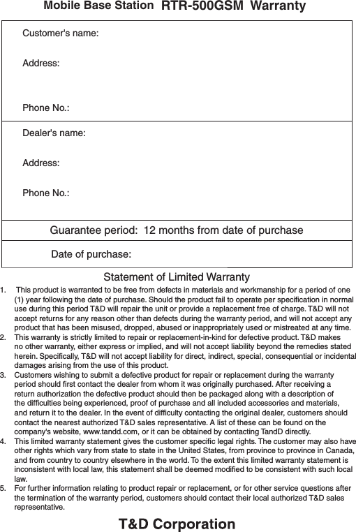
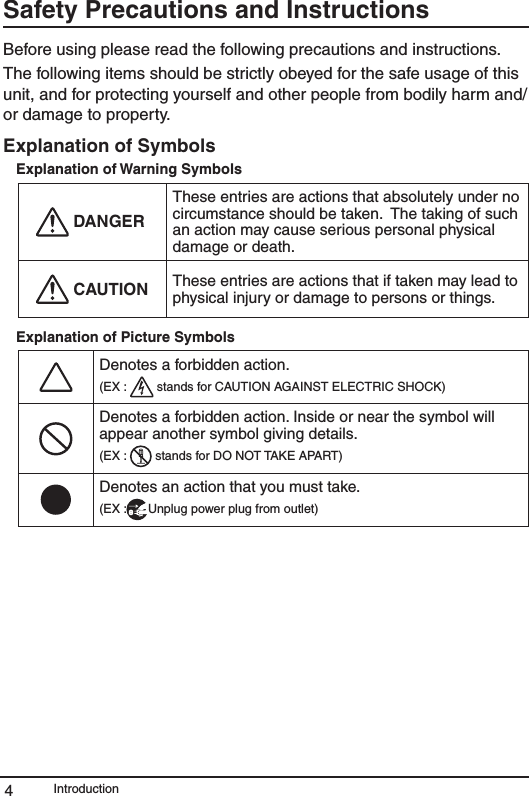
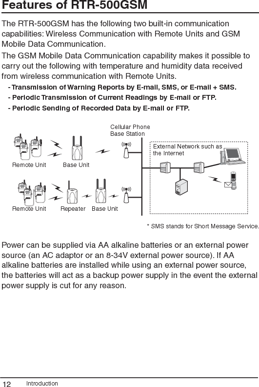
![Introduction10Basic Procedures The following outline shows the basic procedures for getting ready, making settings and using the product. - Details about making settings can be found in [Help and Support] which is located in the drop down menu found by clicking on the program's name under [All Programs] in the [Start] Menu. Getting Ready1. Get the Base Unit (RTR-500GSM) ready to use - Please purchase a SIM card separately. 2. Install the software "RTR-500GSM for Windows"3. Install the USB device driver and confirm its usage.4. Make Initial Settings for the RTR-500GSM- From the RTR-500GSM Settings Utility in the supplied software5. Get Remote Units ready to use - For details, see the User’s Manual that accompanies the Remote Unit. 6. Get the Repeaters ready to use (only if necessary) - For details, see the User’s Manual that accompanies the Repeater Unit. Getting Ready (using supplied software)1. Make Base Unit operational settings 2. Register Remote Units and Repeaters and make necessary settings. 3. Make settings for the transmission of Current Readings, Warning Reports, and for the Auto-downloading of Data4. Carry out transmission tests](https://usermanual.wiki/TandD/10010/User-Guide-1161421-Page-14.png)
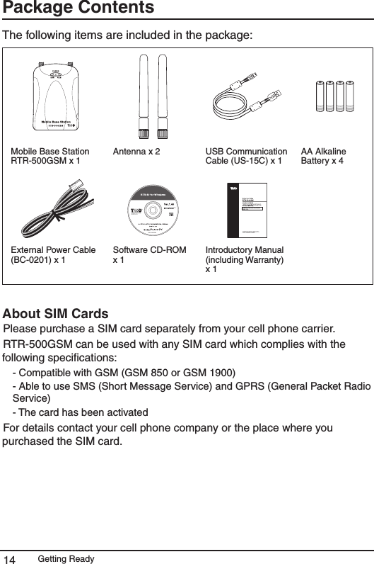
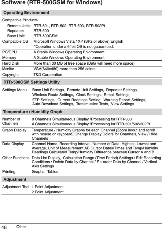
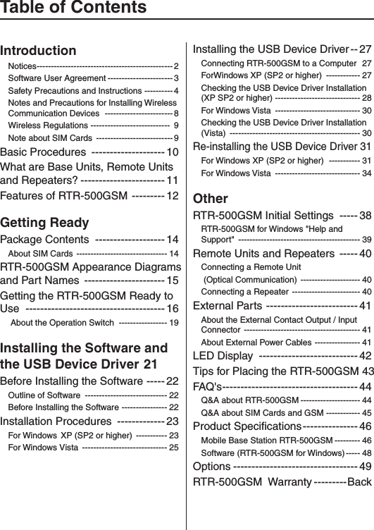
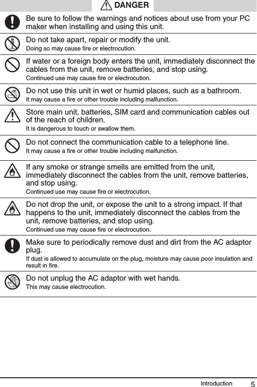
![Installing the Software and the USB Device Driver22Before Installing the SoftwareBefore connecting an RTR-500GSM to your computer, make sure to install the supplied software into the computer. If you have connected an RTR-500GSM to your computer before installing the supplied software, make sure to click the [Cancel] button in the Wizard window when it pops up on the computer display.Slide the Operation Switch on the RTR-500GSM to the <STBY> position.Outline of Software "RTR-500GSM for Windows" is made up of three applications. RTR-500GSM Settings UtilityThis application is designed to register Remote Units and Repeaters and make necessary operational settings for the Base Unit RTR-500GSM and Remote Units. Temperature and Humidity GraphThis application is designed to enable viewing in graph form the temperature and humidity data files. Adjustment This application allows for adjustments to correct inaccuracies found in measured values when compared to a standard or reference measurement. After adjustment settings have been made the data logger will record only the adjusted value. Before Installing the SoftwareIs Windows working properly?- If Windows is not activated properly, it may be impossible to install and run "RTR-500 GSM for Windows".- "RTR-500 GSM for Windows" is compatible with Microsoft Windows XP Service Pack 2 or higher and Vista. For details about the operating environment, see page 48. Quit all applications.- If you are running other applications, make sure to quit them before installation. If you have any permanently active software, such as a virus check or scan program in your computer, make sure to also quit it.For Windows XP and Vista, in order to install RTR-500GSM for Windows, it is necessary to have Administrator rights (Computer Administrator) for the computer in which you wish to install it.](https://usermanual.wiki/TandD/10010/User-Guide-1161421-Page-26.png)
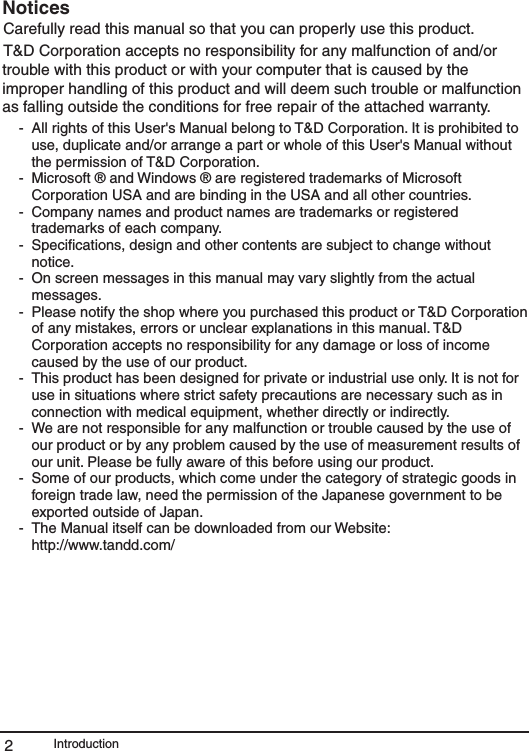
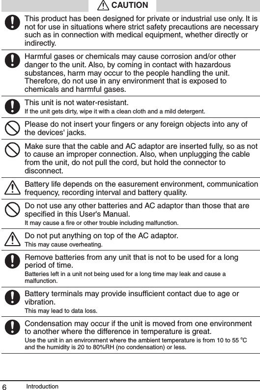
![Installing the Software and the USB Device Driver 23Installation Procedures For Windows® XP (SP2 or higher) 1. Open Windows. 2. Place the supplied software (CD) into the CD-ROM drive. The "Install Program" window will appear soon. * If the "Install Program" window does not automatically open, please open it by double clicking on the CD drive icon in [My Computer]. 3. Select [Install RTR-500GSM for Windows] and click the [Execute] button to start the installation. Click the [Execute] Button4. If a window appears such as the one below during installation, click the [Continue Anyway] button.](https://usermanual.wiki/TandD/10010/User-Guide-1161421-Page-27.png)
![Installing the Software and the USB Device Driver245. After the installation has been completed, please install the USB Device Driver. - See page 27 for details.After installation has been completed, "RTR-500 GSM for Windows" will be registered in the Window's [Start] Menu.](https://usermanual.wiki/TandD/10010/User-Guide-1161421-Page-28.png)
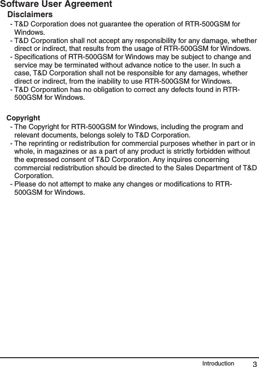
![Installing the Software and the USB Device Driver 25For Windows® Vista 1. Open Windows. 2. Place the supplied software (CD) into the CD-ROM drive. * If the [Auto Play] window appears, under [Install or run program], click on [Run Start.exe]. Click the "Run Start.exe"3. The "Install Program" window will appear. * If that window does not automatically open, please open it by double clicking on the CD drive icon in [Computer]. 4. After clicking the [Execute] button, the [User Account Control] window will appear. Click the [Execute] Button](https://usermanual.wiki/TandD/10010/User-Guide-1161421-Page-29.png)
![Installing the Software and the USB Device Driver265. If a window appears such as the one below during installation, click the [Install] button. 6. After installation has been completed, please check whether the USB device driver has been properly installed. - See page 30 for details.After installation has been completed, "RTR-500 GSM for Windows" will be registered in the Window's [Start] Menu.](https://usermanual.wiki/TandD/10010/User-Guide-1161421-Page-30.png)
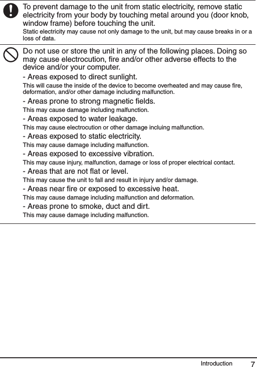
![Installing the Software and the USB Device Driver 27Installing the USB Device DriverHave you already installed the supplied software? Before connecting an RTR-500GSM to your computer via USB, make sure to install the supplied software into the computer. Connecting an RTR-500GSM to a Computer Connect the RTR-500GSM with the supplied USB communication cable to the computer. - Make sure that the USB cable is inserted fully, so as not to cause an improper connection.- Please login using a User Account with Administrator (Computer Administrator) rights. For Windows® XP (SP2 or higher)1. By connecting the RTR-500GSM to the computer, the [Found New Hardware] Wizard will automatically open. - If that window does not automatically open, installation may have been completed or failed. Please check whether the USB device driver has been properly installed by following the directions on page 28. 2. Check "No, not this time" and then click the [Next] button. Check the"No, not this time".](https://usermanual.wiki/TandD/10010/User-Guide-1161421-Page-31.png)
![Installing the Software and the USB Device Driver283. By checking "Install the software automatically (Recommended)" and clicking [Next], the software will automatically be installed. �Check the"Install the software automatically (Recommended)"4. If a window appears such as the one below during installation, click the [Continue Anyway] button. 5. After installation has been completed, please check whether the USB device driver has been properly installed. Checking the USB Device Driver Installation (XP SP2 or higher) 1. Open the System Properties Window by opening [Control Panel] and double clicking on [System].](https://usermanual.wiki/TandD/10010/User-Guide-1161421-Page-32.png)
![Installing the Software and the USB Device Driver 292. In the [System Properties] window, click the [Hardware] tab, and then click the [Device Manager] button in the Device Manager area. [Hardware] Tab[Device Manager] Button3. If under "Port (COM & LPT)" appears "TandD General UsbUart Port" the USB device driver has been properly installed. If successfulIf failed (ex.) - "TandD General UsbUart Port" will not appear if the RTR-500GSM has not been connected to the computer. - If "? Other Device" – "?! TandD USB-UART Controller" appears, it means the USB device driver was not properly installed. Please reinstall by following the directions on page 31.](https://usermanual.wiki/TandD/10010/User-Guide-1161421-Page-33.png)
![Installing the Software and the USB Device Driver30For Windows Vista For Windows Vista, by installing the supplied software, the USB device driver will also be automatically installed. Please check whether the USB device driver has been properly installed. Checking the USB Device Driver Installation (Vista) 1. Connect the RTR-500GSM with the supplied USB communication cable to the computer. 2. Open the Device Manager Window by opening [Control Panel] and clicking on [System and Maintenance] – [System] - [Device Manager]. 3. If under "Port (COM & LPT)" appears "TandD General UsbUart Port" the USB device driver has been properly installed. If successfulIf failed (ex.) - "TandD General UsbUart Port" will not appear if the RTR-500GSM has not been connected to the computer. - If "? Other Device" – "?! TandD USB-UART Controller" appears, it means the USB device driver was not properly installed. Please reinstall by following the directions on page 34.](https://usermanual.wiki/TandD/10010/User-Guide-1161421-Page-34.png)
![Installing the Software and the USB Device Driver 31Re-installing the USB Device DriverFor Windows XP (SP2 or higher) 1. In the Device Manager window, right click on the unknown device "TandD USB-UART Controller". From the pop-up menu click on "Properties". 2. In the "TandD USB-UART Controller Properties" window, click the [General] tab, and then click on the [Reinstall Driver] button to display the [Found New Hardware] Wizard. [General] Tab[ReInstall Driver] Button](https://usermanual.wiki/TandD/10010/User-Guide-1161421-Page-35.png)
![Installing the Software and the USB Device Driver323. Check "No, not this time" and then click the [Next] button. Check the"No, not this time".4. Check "Install from a list or specific location (Advanced)" and then click the [Next] button. Check the "Install from a list or specific location (Advanced)"](https://usermanual.wiki/TandD/10010/User-Guide-1161421-Page-36.png)
![Installing the Software and the USB Device Driver 335. Check "Include this location in the search" and then click the [Browse] button to specify the location of the device driver. Click [Next] to start the installation. Check the "Include this location in the search:"[Browse] Button to specify the location of the device driver- In the "RTR-500GSM for Windows" folder, select "Driver RTR-500". EX: C:\Program Files\RTR-500GSM for Windows\Driver RTR-500 6. If a window appears such as the one below during installation, click the [Continue Anyway] button. 7. After the installation has been completed, please check whether the USB device driver has been properly installed.](https://usermanual.wiki/TandD/10010/User-Guide-1161421-Page-37.png)
![Installing the Software and the USB Device Driver34For Windows Vista 1. In the Device Manager window, right click on the unknown device "TandD USB-UART Controller". From the pop-up menu click on "Properties". 2. In the "TandD USB-UART Controller Properties" window, click the [General] tab, and then click on the [Reinstall Driver] button to display the [Update Driver Software TandD USB UART Controller]. [Reinstall Driver] Button[General] Tab](https://usermanual.wiki/TandD/10010/User-Guide-1161421-Page-38.png)
![Installing the Software and the USB Device Driver 353. Click the "Browse my computer for driver software". Click the "Browse my computer for driver software"4. Click the [Browse] button to specify the location of the device driver. Click [Next] to start the installation. Check here[Browse] button to specify the location of the device driver. - In the "RTR-500GSM for Windows" folder, select "Driver RTR-500". EX: C:\Program Files\RTR-500GSM for Windows\Driver RTR-500](https://usermanual.wiki/TandD/10010/User-Guide-1161421-Page-39.png)
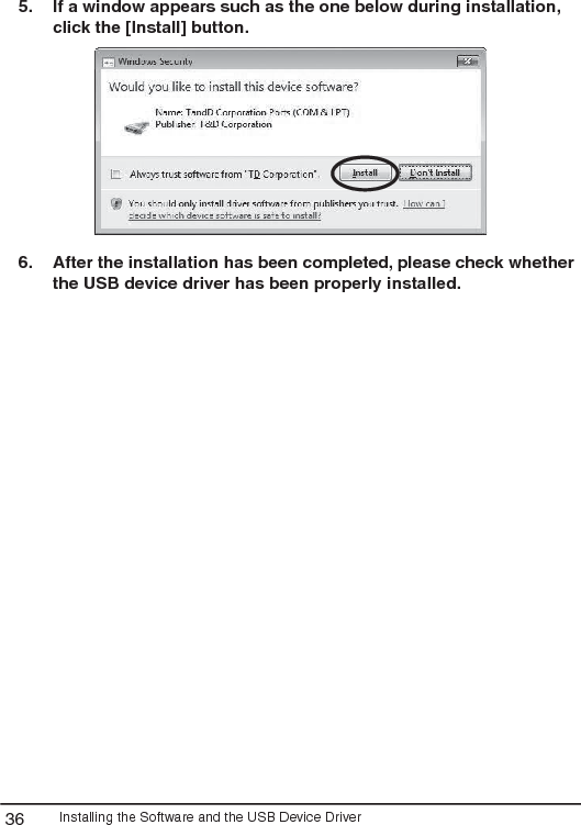
![Installing the Software and the USB Device Driver365. If a window appears such as the one below during installation, click the [Install] button. 6. After the installation has been completed, please check whether the USB device driver has been properly installed.](https://usermanual.wiki/TandD/10010/User-Guide-1161421-Page-40.png)
![Other38RTR-500GSM Initial Settings Check the following before making initial settings Have the SIM card and batteries been installed correctly? Has the RTR-500GSM been connected with a USB cable to your computer? Is the Operation Switch on the RTR-500GSM set to <STBY>? Is the LED <Power> lamp (green) ON? 1. From the list of programs in the Windows Start Menu, click on [RTR-500GSM for Windows] - [RTR-500GSM Settings Utility] to open. 2. The [RTR-500GSM Initial Settings Wizard] window will automatically appear. Follow the instructions as they appear on the screen to make settings. - For details about making settings using the "Initial Settings Wizard", see the explanation in the RTR-500GSM Settings Utility Help. [Help] Button If the Wizard window does not automatically open: From the "View" Menu in the RTR-500GSM Settings Utility, select "Initial Settings Wizard" to open the window. [View] Menu](https://usermanual.wiki/TandD/10010/User-Guide-1161421-Page-42.png)
![Other 39RTR-500GSM for Windows "Help and Support" Details about how to use each application and its functions can be found in the Software "Help". Select "Help and Support" under "RTR-500GSM for Windows", or open the [Help] menu that is in each RTR-500GSM for Windows application. [Help] MenuAlso, by clicking on the [Help] button in each settings window, an explanation for that window will appear. [Contents] Tab[Search] Tab[Contents] TabBy clicking on one of the topics listed, you can find detailed information for that subject.[Search] TabEnter the key word you wish to search for and click the [Start Search] button and the topic in which the key word is included will be displayed. Then select the topic and click the [Display] button to have the explanation displayed.](https://usermanual.wiki/TandD/10010/User-Guide-1161421-Page-43.png)
![Other 43Tips for Placing the RTR-500GSM We strongly suggest setting the RTR-500GSM unit up in a high, unobstructed position to enhance the radio signal strength. When positioning the units try to keep the antennas away from objects or walls. Please carry out a *Signal Strength Test to check the radio signal strength before using the product and adjust the antenna direction accordingly. For more details please see "Notes and Precautions for Installing Wireless Communication Devices" on page 8. * Signal Strength Tests are tests carried out for checking the wireless signal strength between Base, Remote, and Repeater Units after the units have been deployed and settings had been completed. Use the [Wireless Route Settings] menu in the RTR-500GSM Settings Utility to carry out this test.](https://usermanual.wiki/TandD/10010/User-Guide-1161421-Page-47.png)

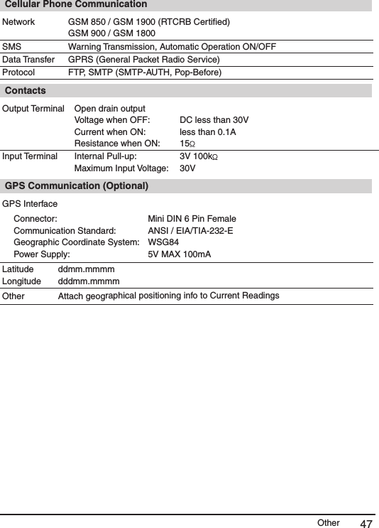
![Other46Product SpecificationsMobile Base Station RTR-500GSM UNITCompatible DevicesRemote Units:Repeater:RTR-501 / RTR-502 / RTR-503 / RTR-502PtRTR-500Functions Auto-download of Recorded Data, Warning Monitoring, Automatic Sending of Current ReadingsPower Source AA alkaline batteries x 4 , 8-34V external power source AC Adaptor AD-0605 (5V) Voltage Consumption At most 2A (5V, with GSM in operation)Communication Interface USB (with PC) / Optical Communication (with Remote Unit)LED Display POWER: GreenERR: OrangeALM: RedBattery Life 10 days of continued use if monitoring is carried out every 10 minutes (when not using GPS). * Battery life varies depending upon the frequency of communication, the measuring environment, and the quality of the battery being used. Dimensions H96mm x W66mm x D39mm , Antenna length 109mm* Excluding protrusionsWeight Approx. 220g (including batteries) Operating Environment Temperature:Humidity:10 ~ 55 oC ( -10 to 55 oC when external power connected)20 ~ 80%RH (Without dew condensation) Wireless CommunicationRf Power 7mWCommunication Method FCC Part15 Section247 / IC RSS-210 [ Frequency Range: 902 to 928MHz ]Communication Range About 150m (500 ft : if direct and unobstructed) Communication Speed When downloading 1 Remote Unit of full data (16,000 readings): about 2 minutes * The same amount of time will be necessary for each added Repeater.](https://usermanual.wiki/TandD/10010/User-Guide-1161421-Page-50.png)