TandD RTR50 Wireless Communication Port User Manual
TandD Corporation Wireless Communication Port
UserManual.wiki
>
TandD
>
RTR50 User Manual
>
Users Manual
Contents
1.
Users Manual
2.
Users Manual Supplement
Users Manual
Navigation menu
Upload a User Manual
Namespaces
Wiki Guide
HTML
PDF
Info
Views
User Manual
Discussion / Help
Navigation

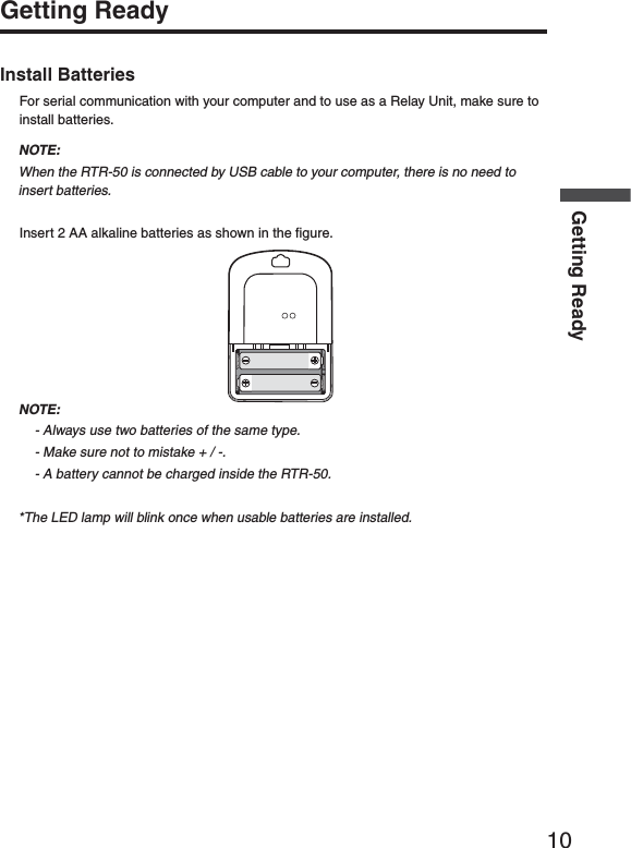
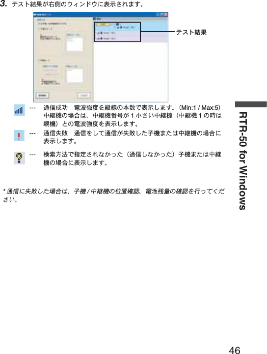
![iiiTable of ContentsSoftware User Agreement ------------------- iiEscape Clauses ----------------------------------iiCopyright ------------------------------------------- iiSafety Precautions and Instructions ------ vTo ensure safety be sure to obey all of the following warnings. -------------------------------v1. IntroductionWhat is Wireless COMMUNICATION PORT RTR-50? -----------------------------------------3Application Examples ---------------------------3What is RTR-50 for Windows®? ------------4Outline ----------------------------------------------4Basic Functions ----------------------------------4Package Contents -----------------------------6Part Names and Functions ------------------7Appearance Diagram ---------------------------72.Getting ReadyGeneral Procedure ----------------------------9Getting Ready --------------------------------10Install Batteries --------------------------------- 10Install RTR-50 for Windows® --------------11Connect the RTR-50 with a USB communication cable to your computer 12Installing the USB Device Driver --------- 13Confi rming the USB Device Driver Connection to the Computer -------------- 18Windows® XP / 2000 --------------------------18Windows® Me/98SE ---------------------------19If USB Device Driver Installation Fails -- 20How to Re-install -------------------------------20Connecting the RTR-50 with a serial communication cable to your computer 21Setting up the Communication Port ----- 223.How to useȨRTR-50 for WindowsȩBasic Functions ------------------------------25Open ȨRTR-50 for Windowsȩ ------------25Explanation of Display ------------------------25Main Unit Info ----------------------------------- 27Remote Unit / Relay Unit Registration -- 28Basic Procedure for Registration ----------- 28Registering a Remote Unit ------------------ 31Deletion and Initialization of Remote Units ------------------------------------ 33Get Remote Unit Recording Settings (Wireless Communication) ------------------- 35Get Remote Unit Info (Optical Communication) --------------------- 37Registering a Relay Unit ---------------------38Connect a Remote Unit via Relay Unit(s) 39Deletion and Initialization of Relay Units -41ಎࠑܥેఠ৾ංȪྫȫ ----------------43ܥ /ಎࠑܥૂ༭৾ංȪೄ୪ȫ -------- 44ྫΞΑΠ ---------------------------------45ݟ̞ષ̬୭ --------------------------------- 47[મळ୭ ]δΗϋ ----------------------------- 49ܱٳই୭ --------------------------------- 50ྫ͈ાࣣ ---------------------------------50͈ાࣣ ------------------------------------51κΣΗςϋΈ /࠙༭۬ণ୭ ------------- 55[κΣΗςϋΈ୭ ] --------------------------55[κΣΗςϋΈۼڞ୭ ]δΗϋ ----------- 55[࠙༭୭ ] ------------------------------------ 56[࠙༭ιȜσ୭ ]δΗϋ -------------------- 56[࠙༭υΈນা ]δΗϋ ----------------------- 56[κΣΗςϋΈȆ࠙༭۬ণٳই ]δΗϋ -- 57κΣΗςϋΈΈρέْ࿂ ---------------------57κΣΗςϋΈΈρέ୭ ---------------------58ιȜσ୭ ---------------------------------------61ু൲ਓਬ୭ --------------------------------- 63[ু൲ਓਬ୭ ] --------------------------------- 63[ু൲ਓਬٳই ]δΗϋ ----------------------- 63[ΟȜΗ༗ంέσΘ ]δΗϋ -------------- 64[ু൲ਓਬυΈນা ]δΗϋ ----------------- 64](https://usermanual.wiki/TandD/RTR50.Users-Manual/User-Guide-760179-Page-4.png)

![7Part Names and FunctionsAppearance Diagram-ONITOR,%$[Front]!#!DAPTORCONNECTIONJACK3ERIAL-INI㧕53"-INI"㧕[Left Side / Right Side][Rear]"ATTERY#OVER/PTICAL#OMMUNICATION0ORT](https://usermanual.wiki/TandD/RTR50.Users-Manual/User-Guide-760179-Page-16.png)

![11Install RTR-50 for Windows®- Is Windows® operating properly ȉIf Windows® is not operating properly, RTR-50 for Windows® may not be installed correctly or it may not operate properly.- Please quit all other applications.If you are running other applications, make sure to quit them before installation.If you have any permanently active software, such as a virus check or scan program in your computer, make sure to also quit it.1. Open Windows®.2. Insert the attached CD-ROM in the CR-ROM drive.In a few seconds, the [Install Program] window will appear.*If that window does not automatically open, please, please open it by double clicking the CD-ROM icon in [My Computer] on your desktop.3. Select [RTR-50 for Windows®] and click the [Execute] button to start the installation.4. Continue the installation by following the directions as they appear. After installation has been completed, "RTR-50 for Windows®" will be registered in Windows' [Start] Menu.When connecting the RTR-50 to your computer for direct communication to download or make setting changes, etcȤ, please use the USB communication cable (provided) or the optional serial communication cable (TR-07C).](https://usermanual.wiki/TandD/RTR50.Users-Manual/User-Guide-760179-Page-20.png)
![13Installing the USB Device DriverYou will need to install this driver in order to use the device with a USB cable and Windows.The USB device driver must be installed for communication via USB between your computer and an RTR-50.After installing the USB device driver, your computer will be able to detect and recognize RTR-50 devices that have been connected with a USB cable.For Windows® XP1. Turn on your computer and open Windows. After Windows has been completely started up, connect the supplied USB cable to a USB port on the RTR-50 and your computer.53"#ABLE53"MINI"0LUG 53"MINI!0LUGTo RTR-50 To PCRTR-502. Insert the attached CD-ROM in the CR-ROM drive.If the Installation Window opens, close it.3. By connecting an RTR-50 unit to the USB cable already connected to your computer, the [Found New Hardware Wizard ] will automatically open.4. By checking [Install the software automatically (Recommended)] and clicking [Next], the software will automatically be installed.[Next]button5. After completing installation, click the [Finish] buttonConfi rm the Connections (see p.18).If the Driver is not automatically detectedPlease search by specifying the place as Ȩ[Device Driver \ RTR-50] in the CD-ROM driveȩ and install manually from there.](https://usermanual.wiki/TandD/RTR50.Users-Manual/User-Guide-760179-Page-22.png)
![14Getting ReadyFor Windows® 20001. Turn on your computer and open Windows. After Windows has been completely started up, connect the supplied USB cable to a USB port on the RTR-50 and your computer.53"#ABLE53"MINI"0LUG 53"MINI!0LUGTo RTR-50 To PCRTR-502. Insert the attached CD-ROM in the CR-ROM drive.If the Installation Window opens, close it.3. By connecting an RTR-50 unit to the USB cable already connected to your computer, the [Found New Hardware Wizard ] will automatically open.4. By clicking the [Next] button, a window will open where you can choose how you wish to fi nd the driver fi le.[Next]button5. Check [Search for a suitable driver for my device (Recommended )] and click the [Next] button.6. Check [CD-ROM drive] and then click the [Next] button.7. Click [Next] to start the installation.8. After completing installation, click the [Finish] buttonConfi rm the Connections (see p.18).If the Driver is not automatically detectedPlease search by specifying the place as Ȩ[Device Driver\ RTR-50] in the CD-ROM driveȩ and install manually from there.](https://usermanual.wiki/TandD/RTR50.Users-Manual/User-Guide-760179-Page-23.png)
![15For Windows® Me1. Turn on your computer and open Windows. After Windows has been completely started up, connect the supplied USB cable to a USB port on the RTR-50 and your computer.53"#ABLE53"MINI"0LUG 53"MINI!0LUGTo RTR-50 To PCRTR-502. Insert the attached CD-ROM in the CR-ROM drive.If the Installation Window opens, close it.3. By connecting an RTR-50 unit to the USB cable already connected to your computer, the [Add New Hardware Wizard ] will automatically open.4. By clicking the [Next] button, a window will open where you can choose how you wish to fi nd the driver fi le.5. Check [Automatic search for a better driver (Recommended )] and click the [Next] button.Check[Next]buttonIf the Driver is not automatically detectedPlease search by specifying the place as Ȩ[Device Driver\ RTR-50] in the CD-ROM drive and install manually from there.](https://usermanual.wiki/TandD/RTR50.Users-Manual/User-Guide-760179-Page-24.png)
![16Getting ReadyFor Windows® 98SE1. Turn on your computer and open Windows. After Windows has been completely started up, connect the supplied USB cable to a USB port on the RTR-50 and your computer.53"#ABLE53"MINI"0LUG 53"MINI!0LUGTo RTR-50 To PCRTR-502. Insert the attached CD-ROM in the CR-ROM drive.If the Installation Window opens, close it.3. By connecting an RTR-50 unit to the USB cable already connected to your computer, the [Add New Hardware Wizard ] will automatically open.4. By clicking the [Next] button, a window will open where you can choose how you wish to fi nd the driver fi le.5. Check [Search for the best driver for your device (Recommended )] and click the [Next] button.check[Next]button](https://usermanual.wiki/TandD/RTR50.Users-Manual/User-Guide-760179-Page-25.png)
![176. Place a check next to [Specify a location] and click the [Browse] button. Select Ȩ[Device Driver\RTR-50] in the CD-ROM driveȩ and click [Next].Select Ȩ[Device Driver\RTR-50] in the CD-ROM driveȩ[Next]button[Browse]button7. After completing installation, click the [Finish] buttonConfi rm the Connections (see p.19).[Finish]button](https://usermanual.wiki/TandD/RTR50.Users-Manual/User-Guide-760179-Page-26.png)
![18Getting ReadyConfi rming the USB Device Driver Connection to the ComputerWindows® XP / 20001. Open the [Control Panel] and double click on [System]; the [System Properties] will be displayed.2. Click the [Hardware] Tab, and click the [Device Manager] button in the [Device Manager] Area.[Hardware] tabDevice Manager3. In the Device Manager Window, check to see if [USB Recorder 2] is listed under [USB Recorder 2 COM].USB Recorder2NOTE:If the following tree items appear, see the ȨIf USB Device Driver Installation Failsȩ (p.20).](https://usermanual.wiki/TandD/RTR50.Users-Manual/User-Guide-760179-Page-27.png)
![19Windows® Me/98SE1. Open the [Control Panel] and double click on [System], the [System Properties] will be displayed.2. In the Device Manager Window, check to see if [USB Recorder 2] is listed under [USB Recorder 2 COM].[Device Manager] tabUSB Recorder2NOTE:If the following tree items appear, see the ȨIf USB Device Driver Installation Failsȩ (p.21).](https://usermanual.wiki/TandD/RTR50.Users-Manual/User-Guide-760179-Page-28.png)
![20Getting ReadyIf USB Device Driver Installation FailsIf, during USB device driver installation, some trouble occurs that results in a failure to install properly, the following display will appear in the Device Manager.If this occurs, the USB device driver must be re-installed.Please follow the directions below to carry out the operation.How to Re-install1. In the Device Manager Window, right click on [USB Device] under [Other Devices] and then click on [Properties] to display the [USB Device Properties] Window.2. In the [USB Device Properties] Window, click on the [Re-install Driver] button to display the Installation Window.Follow the directions to install.[Re-install Driver] button](https://usermanual.wiki/TandD/RTR50.Users-Manual/User-Guide-760179-Page-29.png)
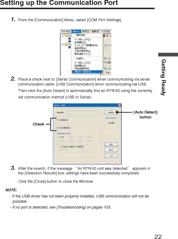
![22Getting ReadySetting up the Communication Port1. From the [Communication] Menu, select [COM Port Settings].2. Place a check next to: [Serial Communication] when communicating via serial communication cable, [USB Communication] when communicating via USB. Then click the [Auto Detect] to automatically fi nd an RTR-50 using the currently set communication method (USB or Serial).[Auto Detect]buttonCheck3. After the search, if the message ȨAn RTR-50 unit was detectedȩ appears in the [Detection Results] box, settings have been successfully completed. Click the [Close] button to close the Window.NOTE:- If the USB driver has not been properly installed, USB communication will not be possible. - If no port is detected, see [Troubleshooting] on pages 103.](https://usermanual.wiki/TandD/RTR50.Users-Manual/User-Guide-760179-Page-31.png)
![25Basic FunctionsOpen ȨRTR-50 for WindowsȩFrom the list of programs in the Windowȧs Start Menu, click on [RTR-50 for Windows] - [RTR-50 for Windows] to open.Explanation of DisplayȨRTR-50 for Windowsȩ Main Window୭ςͺঊܥ֚။ঊܥίυΩΞͻMenu Bar](https://usermanual.wiki/TandD/RTR50.Users-Manual/User-Guide-760179-Page-34.png)
![26RTR-50 for WindowsMenu Bar[File] MenuOpen Temp/Humidity Graph / Open Multi-scale Graph / Open Event Viewer / Open Remote Registration File / Save as... / Quit [Communication] MenuWireless Communication:Download Data/ Start Recording / Monitoring / Warning Monitoring / Auto Download / Get Remote Unit Status / Wireless Communication TestOptical Communication:Download Data / Start Recording / Get Remote Unit Info / Communication Port Settings[Settings] MenuMonitoringMonitoring Graph Settings / View Warning Log / Warning Report Mail Settings / Mail Server SettingsAuto DownloadView Auto Download Log[Registration] MenuRemote Unit / Relay Unit RegistrationRemote Unit Group ListThe Group and Remote Unit names will be displayed for all Remote Units that are registered to that Group in the [Remote Unit / Relay Unit Registration].By right clicking on the Remote Unit icon, a menu will appear with commands for that type of unit.](https://usermanual.wiki/TandD/RTR50.Users-Manual/User-Guide-760179-Page-35.png)
![27Remote Unit Properties (Remote Unit Info List)View Remote Unit Info for the unit(s) selected from the Remote Unit List.Unit Type ---------------The type of unit (RTR-51/52/53 or RVR-52) for the selected Remote Unit(s) will be displayed.Group Name ----------The Group Name appears.Frequency Channel -The Frequency Channel for communication between the Base Unit and the Remote Units appears.Remote Unit Name --Displays the name of the selected Remote Unit.Relay Route Name --Displays the Name of the Relay Route via which the Remote Units communicate.Relay Route Frequency Channel Displays the Frequency Channel of the Relay Route via which the Remote Units communicate.Relay Unit Number --Displays the No. of the Relay Unit via which the Remote Unit is connected.CH1 Upper Limit -----Displays the Upper Limit set in [Monitoring / Warning Monitoring] for Warning Report.CH1 Lower Limit -----Displays the Lower Limit set in [Monitoring / Warning Monitoring] for Warning Report.CH2 Upper Limit*1 --Displays the Upper Limit set in [Monitoring / Warning Monitoring] for Warning Report.CH2 Lower Limit*1 --Displays the Lower Limit set in [Monitoring / Warning Monitoring] for Warning Report.Monitoring Interval ---Displays the currently set Monitoring Interval.Auto Download Interval Displays the currently set Auto Download Interval.*1ȇFor RTR-53 only Settings AreaThere are four different types of Settings windows: [Download Data] Tab, [Start Recording] Tab, [Monitoring / Warning Monitoring] Tab, and [Auto Download] Tab.Main Unit InfoOpen the [Main Unit Info] in the [Help] menu to view the Version Info for the currently connected RTR-50 Unit.It is also possible to view the battery condition in the RTR-50 Unit.](https://usermanual.wiki/TandD/RTR50.Users-Manual/User-Guide-760179-Page-36.png)
![31Registering a Remote Unit1. Connect the RTR-50 Main Unit with a USB or Serial Communication Cable to your computer.2. In the Main Window, click [Registration] – [Remote Unit / Relay Unit Registration].3. The [Remote Unit / Relay Unit Registration] display will be opened in a new window.ΈσȜίྴঊܥྴ[૧ܰഴȪȫ]δΗϋ[୭Ȫȫ]δΗϋਔ෨ତ๔4. Place the Remote Unit (data logger) you wish to register face down on top of the RTR-50. After entering the Group Name and Remote Unit name, click the [New Registration (Communication)] button.*Up to 8 characters can be entered for Group Name / Remote Unit Name.A distinction will be made between upper and lower case alphabet. Ex. abc123 and ABC123 will be treated as different.*In order to register a Remote Unit, it is also necessary to register a Group Name.](https://usermanual.wiki/TandD/RTR50.Users-Manual/User-Guide-760179-Page-40.png)
![32RTR-50 for Windows5. When successful communication has occurred, the Remote Unit will be registered in the registration list at the left side of the Main Window.The registered Remote Unit*The registered Remote Unit(s) will appear as [Group Name / Remote Name].6. Register Remote Units Sequentially.Communication Frequency Channel- It is possible to set one Communication Frequency Channel (channel 0-21) to each Group.- If no setting is made, an unused frequency channel will automatically be assigned.If there are no unused frequency channels, the channel that is used the least shall be automatically assigned.-Communication Frequency Channel settings can only be made when registering a new Group. Once a Communication Frequency Channel setting has been made it cannot be changed.](https://usermanual.wiki/TandD/RTR50.Users-Manual/User-Guide-760179-Page-41.png)
![33[Get Settings (Communication)] ButtonClicking this button will receive the Registration Info for already registered Remote Units (current settings).Place the Remote Unit (data logger) for which you wish to receive settings face down on top of the Base Unit and click the [Get Settings (Communication)] Button.When successful communication has occurred, the Group Name and Remote Unit Name will appear.If you wish to register the currently displayed Remote Registration Contents without any changes, click the [New Registration (Communication)] Button to add the received registration info.Deletion and Initialization of Remote UnitsRegistered Remote Units can be deleted, initialized, or deleted in GroupsClick on the [Remote Unit] – [Remote Info / Delete / Initialize] Tab to open the [Remote Info / Delete / Initialize] window.Remote Unit DeletionSelect the Remote Unit to be deleted from the registration list and click the [Delete Remote Unit] button.ॉੰ̱̹̞ঊܥ఼ͬ[Delete Remote Unit] button](https://usermanual.wiki/TandD/RTR50.Users-Manual/User-Guide-760179-Page-42.png)
![34RTR-50 for WindowsUnit] Group DeletionSelect the Group to be deleted from the registration list and click the [Delete Group] button.NOTE:By deleting a Group, it will become impossible to communicate with all Remote Units registered to that Group.If you wish to carry out communication with any such units they must be re-registered or initialized.Select the Group to be deleted [Delete Group] buttonRemote Unit InitializationPlace the Remote Unit that you wish to initialize on top of the Base Unit connected to your computer and click the [Initialize Remote Unit (Communication)] button.[Initialize Remote Unit (Communication)] button](https://usermanual.wiki/TandD/RTR50.Users-Manual/User-Guide-760179-Page-43.png)
![35NOTEȇ- By initializing, all info saved in the Remote Unit will be erased and will be returned to as it was when it left the factory.The Default Settings are Group Name: Group 1 / Remote Unit: Sr001 / Communication Frequency: 0- When initializing a currently registered Remote Unit, the Registration Info will also be erased from the registration list.Get Remote Unit Recording Settings (Wireless Communication)It is possible to gather the current Remote Unit Recording Settings: Recording Mode / Type of Data / Recording Status / Current Readings / Radio Wave Strength / Battery Level by selecting [Get Remote Unit Recording Settings (Wireless Communication)].Recording Mode -----------The selected recording mode will be displayed: Endless or One Time.Endless Mode--- When the logger has reached its maximum number of readings (16,000 readings possible / 8,000 of Temp and Humidity for RTR-53), the oldest data reading will be overwritten and recording will continue.One-time Mode--- Recording will automatically stop when the logger has reached its maximum number of readings (16,000 readings possible / 8,000 of Temp and Humidity for RTR-53).Type of Data ----------------Temperature, Humidity, Voltage, Pulse, Event can be viewed here.Current Readings ---------The currently recorded data is displayed here.Radio Wave Strength -----Displays the Radio Wave Strength of wireless communication between Units.(0 – Weak < 5 – Strong)Battery Level ----------------The remaining battery level for the Remote Unit will be displayed.(0 – No Battery < 5 – Full)](https://usermanual.wiki/TandD/RTR50.Users-Manual/User-Guide-760179-Page-44.png)
![36RTR-50 for Windows1. Check if the Base Unit is properly connected to the computer.2. From the registration list, select the Remote Unit which you wish to view the Registration Recording Settings from and click the [Get Remote Unit Recording Settings (Wireless Communication)] Tab.ঊܥૂ༭৾ං̱̹̞ঊܥ఼ͬ[Communication] button [Get Remote Unit Recording Settings (Wireless Communication)] Tab3. Click the [Communication] button.NOTEȇIf a communication error has occurred, please check the communication status by carrying out aȨWireless Communication Test.ȩ(See p. 44 for details)](https://usermanual.wiki/TandD/RTR50.Users-Manual/User-Guide-760179-Page-45.png)
![37Get Remote Unit Info (Optical Communication)It is possible to gather the current Remote Unit Info: Group Name / Frequency Channel / Remote Unit name / Registration Status by selecting [Get Remote Unit Info (Optical Communication)].Group Name ----------Group Name will be displayed.Frequency Channel -Frequency Channel will be displayed.Remote Unit Name --Remote Unit Name will be displayed.Registration Status --Displays whether the Remote Unit has been registered in the Remote Unit Registration List or not. 1. Place the Remote Unit you wish to view the Registration Info from face down on the Base Unit that is connected to your computer.2. Select the [Get Remote Unit Info (Optical Communication)] Tab and click the [Get Remote Unit Info (Communication)] button.[Get Remote Unit Info (Communication)] button[Get Remote Unit Info (Optical Communication)] Tab](https://usermanual.wiki/TandD/RTR50.Users-Manual/User-Guide-760179-Page-46.png)
![38RTR-50 for WindowsRegistering a Relay Unit1. Connect the Relay Unit you wish to register to your computer with a USB or Serial Communication Cable.2. Click the [Relay Unit] Tab and enter a Relay Route Name. Then click the [New Registration (Communication)] button.Relay Route NameMemo[Relay Unit] Tab[New Registration (Communication)] button[Memo]It is helpful to make a memo entry here in order to distinguish between Relay Units.(Up to 8 characters can be entered.) You may leave this fi eld blank if not necessary and should note that changes cannot be made after registering a Relay Unit.If you wish to make changes, it is necessary to create the Relay Route again.](https://usermanual.wiki/TandD/RTR50.Users-Manual/User-Guide-760179-Page-47.png)
![40RTR-50 for Windows2. The message [Relay Settings for Selected Remote Completed] will appear and the Remote Unit will be added under the location in the Relay Route in the Registration List.Removing a Remote Unit from a Relay Route1. Select the Remote Unit which you wish to remove from the Relay Route. Then drag the Remote Unit to the Base Unit Icon and drop it.2. The location of the Remote Unit will be returned just under the Base Unit in the registration list.*Also, by a right clicking the mouse and then clicking on [No Relay], the location of the Remote Unit will be returned to the Base Unit as above.](https://usermanual.wiki/TandD/RTR50.Users-Manual/User-Guide-760179-Page-49.png)
![41Deletion and Initialization of Relay UnitsRegistered Relay units can be deleted or initialized.Click on the [Relay Unit] – [Relay Unit Info / Delete / Initialize] Tab to open the [Relay Unit Info / Delete / Initialize] window.Relay Unit / Relay Route DeletionSelect the Relay Unit to be deleted from the registration list. Click the [Delete Relay Unit] if you wish to delete only the Relay Unit and click the [Delete Route] if you wish to delete the Relay Route.Select the Relay Unit to be deleted[Delete Route] button [Delete Relay Unit]buttonNOTEȇIf you wish to delete a Relay Route, the location of all Remote Units belonging to it will be returned to just under the Base Unit in the Registration List.](https://usermanual.wiki/TandD/RTR50.Users-Manual/User-Guide-760179-Page-50.png)
![42RTR-50 for WindowsRelay Unit Replacement (For changing a Relay Unit with a new one due to malfunction or trouble)Select the Relay Unit you wish to replace from the Registration List and connect the one you wish to newly register to your computer with a USB or Serial Communication Cable.Click the [Replace Unit] button.ಕփȇഴඤယ͉Ȃஜ͈ಎࠑܥ̧͈͈ͬ֨͜ࠑ̨̳͘ȃུఘ̱̹̞۟ಎࠑܥ఼ͬ[ུఘ۟Ȫȫ]δΗϋಎࠑܥ͈ܢاȪܥͅ࿗̳ȫܢا̱̹̞ಎࠑܥ͂ΩΕϋͬ USB ̹͉͘ΏςͺσΉȜήσ́୪̱Ȃ[ܢاȪȫ]δΗϋͬ·ςΛ·̱̳͘ȃ[ܢاȪȫ]δΗϋ](https://usermanual.wiki/TandD/RTR50.Users-Manual/User-Guide-760179-Page-51.png)
![43ಕփȇܢا࣐̠࡛ͬ͂हಎࠑܥͅഴ̯̞ͦ̀ͥૂ༭͉̀ॉੰ̯ͦȂܢેఠȪكশ͈ેఠȫ̳̈́ͤ͘ͅȃRTR-50 ͈ܢેఠ͉Ȃܥ̱͂̀୭̯̞̳ͦ̀͘ȃಎࠑܥેఠ৾ංȪྫȫঐ̯̹ͦσȜΠ͈ಎࠑܥેఠͬ৾ං̱̳͘ȃಎࠑܥ๔ ------------ڎಎࠑܥ͈๔ͬນা̱̳͘ȃഩ෨ޑഽ ---------------ڎಎࠑܥۼ͈ഩ෨ޑഽͬນা̱̳͘ȃȪ0ȇ৻̞ɨ 5ȇޑ̞ )*ুͤ͢ 1̾PC ͅ߃̞ಎࠑܥȪ̹͉͘ܥȫۼ͈ྫ͈ഩ෨ޑഽ̳́ȃഩ౻ॼၾ ---------------ڎಎࠑܥ͈ഩ౻ॼၾͬນা̱̳͘ȃȪ0ȇॼၾ̱̈́ɨ 5ȇ૧ȫ1. ಎࠑܥેఠͬ৾ං̱̹̞ಎࠑσȜΠͬ୪֚။఼̥̱̳ͣ͘ȃ2. [ಎࠑܥેఠ৾ං ]Ηή఼̱ͬȂ[ ]δΗϋͬ·ςΛ·̱̳͘ȃ[ ]δΗϋ[ಎࠑܥેఠ৾ංȪྫȫ]Ηήಎࠑܥ఼̳ͬͥ3. ࠫض̦ນা̯̳ͦ͘ȃಕփȇͅ෴̱̹ાࣣȂ[ྫΞΑΠ ]́ഩ෨͈ږ̱̩̺̯̞ͬ̀ȃȪP. 4 4 ४ચȫ](https://usermanual.wiki/TandD/RTR50.Users-Manual/User-Guide-760179-Page-52.png)
![44RTR-50 for Windowsܥ /ಎࠑܥૂ༭৾ංȪೄ୪ȫഴ̯̞ͦ̀ͥȂܥ̹͉͘ಎࠑܥ͈ૂ༭ͬ৾ං̧̳̭̦̳ͥ͂́͘ȃܥ͈ાࣣഩ౻ॼၾ ---------------ഩ౻ॼၾͬນা̱̳͘ȃȪ0ȇॼၾ̱̈́ɨ 5ȇ૧ȫಎࠑܥ͈ાࣣಎࠑσȜΠྴ ---------ಎࠑσȜΠྴͬນা̱̳͘ȃਔ෨ତ ------------------ಎࠑܥ̦௺̳ͥಎࠑσȜΠ͈ਔ෨ତ๔ͬນা̱̳͘ȃಎࠑܥ๔ ------------ಎࠑܥ๔ͬນা̱̳͘ȃഩ౻ॼၾ ---------------ഩ౻ॼၾͬນা̱̳͘ȃȪ0ȇॼၾ̱̈́ɨ 5ȇ૧ȫ1. ૂ༭ͬ৾ං̱̹̞ܥ̹͉͘ಎࠑܥͬΩΕῧ USB ̹͉͘ΏςͺσΉȜήσ́୪̱̳͘ȃ2. [ܥ /ಎࠑܥૂ༭৾ංȪೄ୪ȫ]Ηή఼̱ͬȂ[ૂ༭৾ංȪೄ୪ȫ]δΗϋͬ·ςΛ·̱̳͘ȃ[ૂ༭৾ංȪȫ]δΗϋ[ܥ /ಎࠑܥૂ༭৾ංȪೄ୪ȫ]Ηή3. ࠫض̦ນা̯̳ͦ͘ȃ](https://usermanual.wiki/TandD/RTR50.Users-Manual/User-Guide-760179-Page-53.png)
![45ྫΞΑΠ1. [ঊܥ /ಎࠑܥഴ ];ͻϋΡ;͈ [ྫΞΑΠ ]δΗϋͬ·ςΛ·̱̳͘ȃ[ྫΞΑΠ ]δΗϋ2. [ঊܥ /ಎࠑܥͬΞΑΠ̳ͥ ] / [ ঊܥΈσȜί ] / [ ಎࠑσȜΠ ]͈3ਅ႒఼༹̥༷̱ͣ॑ͬȂ[ٳই ]δΗϋͬ·ςΛ·̱̳͘ȃ[ٳই ]δΗϋঊܥ /ಎࠑܥͬΞΑΠ̳ͥ --- ഴ̯̞͈ͦ̀ͥ̀ঊܥ͂ಎࠑܥ͈ΞΑΠ࣐̞̳ͬ͘ȃঊܥΈσȜί -------------------------- ঊܥΈσȜίྴςΑΠ఼̯̹́ͦΈσȜί͈ঊܥ͈ഩ෨ޑഽͬນা̱̳͘ȃಎࠑσȜΠ -----------------------------ȮΞΑΠ͈ঐȯ́ "͈̀σȜΠ "ͬΙͿΛ·̱̹ાࣣ͉͈̀σȜΠͬࠐဇ̳ͥಎࠑܥ͂ঊܥ͈ഩ෨ޑഽͬΞΑΠ̱̳͘ȃ"ঐ̱̹σȜΠ "ͬΙͿΛ·̱̹ાࣣ͉ȮಎࠑσȜΠྴȯςΑΠ́ΞΑΠ̱̹̞ಎࠑσȜΠͬঐ̱̩̺̯̞̀ȃ*ܥ͂ೄ୪̳ͥঊܥ͉ΞΑΠ̵̱ͭ͘ȃ](https://usermanual.wiki/TandD/RTR50.Users-Manual/User-Guide-760179-Page-54.png)
![47ݟ̞ષ̬୭ιͼϋْ࿂ͤ͢Ȃঊܥ 1రȂ̹͉͘ΈσȜί֚گ́ΟȜΗݟ̞ષ̬͈୭̧̦̳́͘ȃ1. ঊܥ 1ర͈ݟ̞ષ̬͈ાࣣȂऒ௰͈ঊܥ֚။̥ͣȂݟ̞ષ̬̹̞ঊܥ఼̱̳ͬ͘ȃΈσȜί֚گ́ݟ̞ષ̬̱̹̞ͬાࣣȂঊܥ֚။̥ͣΈσȜίྴέσΘ఼̱̳ͬ͘ȃঊܥ̹͉͘ΈσȜί఼ͬ[ݟ̞ષ̬ ]δΗϋ[મळ୭ ]δΗϋ2. ༹༷Ȃݟ̞ષ̬ૄͬ୭̱Ȃ[ݟ̞ષ̬ ]δΗϋͬ·ςΛ·̳ͥ͂Ȃݟ̞ષ̬ͬٳই̱̳͘ȃݟ̞ષ̬ࠫض͉Ȃْ࿂ષ͈ [ݟ̞ષ̬ેޙ ]ͅນা̯̳ͦ͘ȃΈσȜίȟঊܥȁȪྫ͈͙ȫঐ̱̹ঊܥ͈͙ঊܥςΑΠ֚။́ঐ̯̹ͦঊܥ 1ర͈ΟȜΗͬݟ̞ષ̬̳͘ȃ ΈσȜί֚گঊܥςΑΠ֚။́ঐ̯̹ͦΈσȜί͈ΟȜΗ֚ͬگ́ݟ̞ષ̬̳͘ȃಕփȇ*ݟ̞ષ̬̹έͼσ͉ু൲എͅ RTR-50 for WIndows ͬͼϋΑΠȜσ̱̹έσΘͅ ȩ ΈσȜίྴ _ঊܥྴ _ັশ࣫ .ڐಫঊ ȩ̞̠͂έͼσྴ́༗ం̯̳ͦ͘ȃ ݟ̞ષ̬ૄܱΟȜΗܱΟȜΗͬݟ̞ષ̬̳͘ȃݟ̞ષ̬শۼঐडਞܱΟȜΗ̥ͣঐশۼஜ͈ܱ́͘ΟȜΗͬݟ̞ષ̬̳͘ȃౙպ͉ 1শۼౙպȆ1ౙպ఼̧̥̳̭̦̳ͣͥ͂́͘ȃݟ̞ષ̬শۼͬঐ̧̱̹͂ͅঐ̯̹ͦশۼ͈ΟȜΗ̦ܱ̯̞̞ͦ̀̈́ાࣣ͉Ȃ࡛ह༗ం̯̞ܱͦ̀ͥΟȜΗͬݟ̞ષ̬̳͘ȃ](https://usermanual.wiki/TandD/RTR50.Users-Manual/User-Guide-760179-Page-56.png)
![49[મळ୭ ]δΗϋݟ̞ષ̬ஜ͈୭Ȃݟ̞ષ̬ࢃ͈ੜၑ఼̧༹༷̳ͬ́͘ȃ[OK] buttonຈါ̈́ࣜ࿒ͅΙͿΛ·̱ͬ̀Ȃ[OK] δΗϋͬ·ςΛ·̳ͥ͂Ȃ୭̯̳ͦ͘ȃΟȜΗݟ̞ષ̬ஜ͈୭শۼ͈ࠗॳ̳ͬͥ ---------- ಎࠑܥͬࠐဇ̱̞̀ͥાࣣͅࡠͤȂఘ͈̥̥ͥͅশۼͬેఠΘͼͺυΈδΛ·ᾼນা̱̳͘ȃ̹̺̱Ȃশۼͬນা̳̹͉ͥ͛ͅಎࠑܥ֚͂ഽ̳ͬͥຈါ̦̜͈ͥ́ 1ঊܥͬݟ̞ષ̬̹ͥ͛ͅȂ̷̤͢ಎࠑܥరତ x 20 ຟ͈শۼ̦ح̯̳ͦ͘ȃশۼͬນা̵̯̹̞ાࣣ͉ͅΙͿΛ·̫̩̺̯̞ͬ̾̀ȃȪಎࠑܥͬࠐဇ̱̞̞̀̈́ાࣣ͉حশۼ͉̩̈́ȂΙͿΛ·͈ခྫͅ۾̴̷̤͈ͩͣ͢শۼ͉ນা̯̳ͦ͘ȃȫΟȜΗݟ̞ષ̬ࢃ͈୭ু൲എͅΈρέນা̳ͥ -----------ݟ̞ષ̬̹ΟȜΗͬু൲എͅΈρέͅນা̱̳͘ȃΟȜΗͬ༗ం̱̹̞ાࣣ͉ͅٳ̞̹Έρέ͈έͼσιΣνȜ̥ͣ༗ం̱̩̺̯̞̀ȃ༗ం̳ͥέͼσྴͬঐ̳ͥ --1 ঊܥΟȜΗͬݟ̞ષ̬̹ࢃͅȮέͼσͬ༗ం̳ͥȯΘͼͺυΈδΛ·Α̦ນা̯͈ͦͥ́Ȃ༗ం̱̹̞έͼσྴͬঐ̱̩̺̯̞̀ȃΈρέͅນা̱̹̞ાࣣ͉ͅ༆ഷ༗ంέͼσͬΈρέ́ٳ̞̩̺̯̞̀ȃ༗ం̳ͥέͼσྴͬঐ̱Έρέͅນা̳ͥ ષܱ͈Ȯ༗ం̳ͥέͼσྴͬঐ̳ͥȯȂȮু൲എͅΈρέͬນা̳ͥȯ̦ਜ਼࣐̯̳ͦ͘ͅȃˍঊܥ̿̾ু൲എͅέͼσͅྴஜ̫ͬ̾̀ވέσΘͅ༗ం̳ͥݟ̞ષ̬̹ΟȜῌু൲എͅέͼσྴ̫ͬ̾̀Ȫ*ΈσȜίྴ /ঊܥྴ /ັশ࣫ȅڐಫঊȫঐ̯̹ͦέσΘͅڒො̯̳ͦ͘ȃة͜ঐ̱̞̞̀̈́ાࣣ͉ু൲എͅͺίςΉȜΏοϋͬͼϋΑΠȜσ̱̹έσΘͅڒො̯̳ͦ͘ȃΈρέͅນা̱̹̞ાࣣ͉ͅ༆ഷ༗ంέͼσͬΈρέ́ٳ̞̩̺̯̞̀ȃ](https://usermanual.wiki/TandD/RTR50.Users-Manual/User-Guide-760179-Page-58.png)
![50RTR-50 for Windowsܱٳই୭ྫȂ̱̩͉́͜Ȃܱٳই͈୭̧̦̳́͘ȃιͼϋْ࿂͈ [ܱٳই ]Ηήͬ·ςΛ·̱̀Ȃܱٳইْ࿂ͬٳ̧̳͘ȃྫ͈ાࣣ[ܱٳই ]Ηή[ܱٳই ]δΗϋ[୭ ]δΗϋ[ܱ೪গ ]δΗϋ1. ঊܥ 1ర͈ܱٳই୭͈ાࣣȂऒ௰͈ঊܥ֚။̥ͣ୭̱̹̞ঊܥ఼̱̳ͬ͘ȃΈσȜί֚گܱ́ٳই୭̱̹̞ͬાࣣȂঊܥ֚။̥ͣΈσȜίྴέσΘ఼̱̳ͬ͘ȃ2. ڎ୭̱ͬȂ[ܱٳই ]δΗϋͬ·ςΛ·̳ͥ͂Ȃ୭̦ۖၭ̱̳͘ȃ[ܱٳই ]δΗϋঐ̯̹ͦૄ́ঊܥ͈ܱͬٳই̱̳͘ȃ*̹̺̱Ȃྫ͈ાࣣ́Ȯྫܱͥ͢ͅٳই̦গȯ̯̞ͦ̀ͥঊܥͅచ̱͉ܱ̀ͬٳই̵̧́ͭ͘ȃમ̱̩͉ [મळ୭ ]δΗϋȪP. 5 3 ȫͬ४ચ̱̩̺̯̞̀ȃ*ܱٳইږιΛΓȜΐΘͼͺυΈδΛ·Αͬນা୭̱̹ͅાࣣȂ"Shift δΗϋ (΅ȜδȜΡ ) ͬ؋̱̦̈́ͣζ;Αֲ·ςΛ· "̳ͬͥ͂ȂষܱٝٳইশͅठഽږιΛΓȜΐΘͼͺυΈδΛ·Α̦ນা̯̳ͦ͘ȃ[୭ ]δΗϋ఼̱̹ঊܥ͈୭̱ͬ̀ນা̱̳͘ȃ[ܱ೪গ ]δΗϋ఼̱̹ঊܥȂ̹͉͘ΈσȜί͈ܱͬ೪গ̱̳͘ȃ*̹̺̱Ȃྫ͈ાࣣ́Ȯྫܱͥ͢ͅٳই̦গȯ̯̞ͦ̀ͥঊܥͅచ̱͉ܱ̀ͬ೪গ̵̧́ͭ͘ȃમ̱̩͉̤ঀ̞͈ঊܥ͈৾ե୰ྶ̮ͬ။̩̺̯̞ȃ](https://usermanual.wiki/TandD/RTR50.Users-Manual/User-Guide-760179-Page-59.png)
![52RTR-50 for Windows௶ౙպ͈୭[મळ୭ ]δΗϋ[ܱ೪গ ]δΗϋ[୭ ]δΗϋ[ܱٳই ]δΗϋ1. ܥਅ఼̱̳ͬ͘ȃ*RVR-52 ఼̱̹ͬાࣣ͉Ȃ௶ౙպ͈୭ࣜ࿒̦ນা̯̳ͦ͘ȃ2. ͈শ͈͙ນা̯ͦͥ [મळ୭ ]δΗϋͬ·ςΛ·̳ͥ͂Ȃྫ͈ίυΞ·Πْ࿂̦ນা̯̳ͦ͘ȃȪP53 ४ચȫ3. ڎ୭̱ͬȂ[ܱٳই ]δΗϋͬ·ςΛ·̳ͥ͂Ȃ୭̦ۖၭ̱̳͘ȃ[ܱٳই ]δΗϋঐ̯̹ͦૄ́ঊܥ͈ܱͬٳই̱̳͘ȃ*ܱٳইږιΛΓȜΐΘͼͺυΈδΛ·Αͬນা୭̱̹ͅાࣣȂ"Shift δΗϋ (΅ȜδȜΡ ) ͬ؋̱̦̈́ͣζ;Αֲ·ςΛ· "̳ͬͥ͂ȂষܱٝٳইশͅठഽږιΛΓȜΐΘͼͺυΈδΛ·Α̦ນা̯̳ͦ͘ȃ[୭ ]δΗϋ఼̱̹ঊܥ͈୭̱ͬ̀ນা̱̳͘ȃ[ܱ೪গ ]δΗϋ఼̱̹ঊܥȂ̹͉͘ΈσȜί͈ܱͬ೪গ̱̳͘ȃܱٳই༹༷ΈσȜί ---------------ঊܥςΑΠ֚။́ঐ̯̹ͦΈσȜίྴ̦ນা̯̳ͦ͘ȃঊܥ ---------------------ঊܥςΑΠ֚။́ঐ̯̹ͦঊܥྴ̦ນা̯̳ͦ͘ȃঐ̱̹ঊܥ͈͙ ---ঐ̯̹ͦঊܥ 1ర͈ܱͬٳই̱̳͘ȃΈσȜί֚گ ---------ঐ̯̹ͦΈσȜί͈ঊܥ̀ͅచ̱֚̀گܱ́ͬٳই̱̳͘ȃܱٳইশထΑΗȜΠ ---------ঊܥུఘ̦ထ̯̹ͦশܱͤͬ͢ٳই̱̳͘ȃܱٳইশ͈වႁ͉ාȂȂȂশȂȂຟȁ͈ౙպ࣐̞̳́͘ȃܢ͉ΘͼͺυΈδΛ·Αܳ൲শ͈শ̦ນা̯̳ͦ͘ȃȪܢ͉ྚྖͬ୨ͤષ̬̜̳̀ͤ͘ȃȫ](https://usermanual.wiki/TandD/RTR50.Users-Manual/User-Guide-760179-Page-61.png)
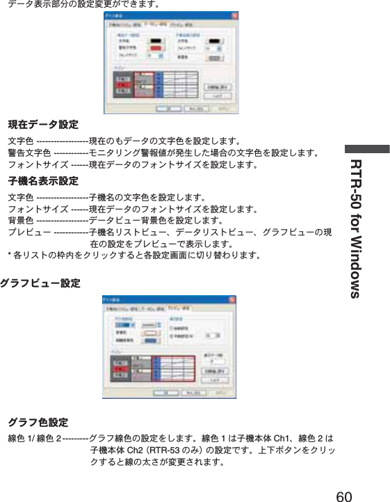
![53௲শΑΗȜΠ ---------ঊܥུఘ̦ೄ̻ܱͬͅٳই̱̳͘ȃܱٳইশ͈වႁ͉ຈါ̵̜ͤͭ͘ȃಕփȇ-ྫ͈ાࣣ͉ͅ௲শΑΗȜΠ̵̧͉́ͭ͘ȃ̹͘ܥ̥ͣঊܥ͈́͘শۼͬࣉၪ̱̀ထশۼͬ୭̱̩̺̯̞̀ȃ࡛ह̥̥̥ͣͥͅশۼͬح̱̹শ࣫ͤ͢͜ထٳইশۼ்̦̞ાࣣ͉ͅΑΗȜΠ̵̧́ͭ͘ȃȪρȜιΛΓȜΐ̦ນা̯̳ͦ͘ȃȫٳইশۼ͈࿒հ̷͉̤͢ 1σȜΠ̜̹ͤ (ಎࠑܥ͈రତ + 1) x 20 ຟ̱̩̺̯̞͂̀ȃ̹͘ȂΈσȜί֚گ́ٳই̳ͥાࣣȂಎࠑܥͬࠐဇ̳ͥঊܥ͞ܥ͂ೄ୪̳ͬͥঊܥ̦̜ͥ୭͈̈́̓ાࣣ͉֚ͅ๔শۼ͈ಿ̞ঊܥͅచ̱͈ܱ̀ٳইထশۼͬ୭̱̩̺̯̞̀ȃ-͈ਜ਼੬൝͉୪֚။͈୰ྶͬ४ચ̱̩̺̯̞̀ȃ ࡛हশ ---------------࡛हশ͉ΩΕϋ͈ΏΑΞθັͬນা̱̞̳̀͘ȃထΑΗȜΠ̳ͬͥાࣣܱٳইশ͉࡛हশͤ͢ྚြ͈শ࣫ͬ୭̱̩̺̯̞̀ȃထশ ---------------୭̯̹ܱͦۼڞȂܱٳইশͤ͢Ȃထਞၭশͬࠗॳ̱̳͘ȃ(ొ̱ȂܱκȜΡͬϋΡτᾼ̱̹ાࣣ͉ນা̵̯ͦͭ͘ȃ)ܱۼڞ1ຟȂ2ຟȂ5ຟȂ10 ຟȂ15 ຟȂ20 ຟȂ30 ຟ Ȃ1Ȃ2Ȃ5Ȃ10 Ȃ15 Ȃ20 Ȃ30 Ȃ60 ఼̧̥̳ͣ́͘ȃܱκȜΡχϋΗͼθκȜΡ ---ܱΟȜΗତ̦ 16000 ࡢȪRTR-53 ͉8000 ࡢȫͅൢోུ̳ͥ͂ఘסએນা໐ͅ FULL ̦ນা̯ͦȂܱͬ೪গ̱̳͘ȃϋΡτΑκȜΡ ---ܱΟȜΗତ̦ 16000 ࡢȪRTR-53 ͉8000 ࡢȫ಼̢ͬͥ͂Ȃ1๔ࡣ̞ΟȜΗ̥ͣષ̧̱Ȃܱ̫̳ͬ͘ȃ[મळ୭ ]δΗϋȪশ͈͙ȫྫܱͥ͢ͅٳইͬগ̳ͥ୭फ͙ঊܥͅచ̱̀ྫܱ́ٳই /೪গ̦࣐̯ͦ̀͜Ȃ̷͈ঊܥ͉ܱ̦ٳই̵̯ͦͭ͘ȃ](https://usermanual.wiki/TandD/RTR50.Users-Manual/User-Guide-760179-Page-62.png)
![54RTR-50 for Windowsྫܱͥ͢ͅٳইͬݺخ̳ͥ୭फ͙ঊܥͅచ̱̀গ୭̦̜ͥાࣣ͉Ȃݺخ̱̀ྫܱ́ٳই /೪গ̧̦̠̳́ͥ̈́ͤ͘͢ͅȃ ಕփȇ[OK] δΗϋͬ·ςΛ·̳̭ͥ͂́Ȃ͈ࣽٝ୭̦ষ͈ܱٝٳইশͅခ̳࢘̈́ͤ͘ͅȃ௶ౙպȪ͈͙ȫȁ*RVR-52 ͈͙ນা̯̳ͦ͘ȃഩգȁȪུఘסએ͈ౙպ͉ഩգ [V]ȁ̳͂̈́ͤ͘ȃȫশ ------------------௶̱̹ۼ͈ഩգܱ̱̳ͬ͘ȃ ------------------ঐ̯̹ܱͦۼڞಎͅ௶̯̹ͦഩգ͈ܱ̱̳ͬ͘ȃΩσΑȪུఘסએ͈ౙպ͉ΩσΑ [P]ȁ̳͂̈́ͤ͘ȃȫၛ̻ئ̦ͤ ------------ΩσΑ͈ၛ̻ئ̦ܱ̱̳ͤͬ͘ȃၛ̻ષ̦ͤ ------------ΩσΑ͈ၛ̻ષ̦ܱ̱̳ͤͬ͘ȃͼαϋΠȪུఘסએ͈ౙպ͉ΩσΑɃ Hi or Lo ɄȮPȯȫ̳͂̈́ͤ͘ȃȫΩσΑͼαϋΠ͈শܱ̱̳࣫ͬ͘ȃ](https://usermanual.wiki/TandD/RTR50.Users-Manual/User-Guide-760179-Page-63.png)
![55κΣΗςϋΈ /࠙༭۬ণ୭༆;ͻϋΡ;́ȂςͺσΗͼθκΣΗͬٳ̧̩̭̦̳͂́͘ȃιͼϋْ࿂͈ [κΣΗςϋΈ /࠙༭۬ণ୭ ]Ηήͬ·ςΛ·̱̀ȂκΣΗςϋΈ /࠙༭۬ণ୭ْ࿂ͬٳ̧̳͘ȃκΣΗςϋΈ֚။̥ͣκΣΗςϋΈ̱̹̞ঊܥȂ̹͉͘ΈσȜί఼̱̳ͬ͘ȃκΣΗςϋΈૂ༭ςΑΠ֚။[κΣΗςϋΈȆ࠙༭۬ণٳই ]δΗϋ [κΣΗςϋΈۼڞ୭ ]δΗϋ[࠙༭ιȜσ୭ ]δΗϋ[࠙༭υΈນা ]δΗϋκΣΗςϋΈૂ༭ςΑΠ֚။ΈσȜίྴ ------------ഴफ͙͈ΈσȜίྴ̦ນা̯̳ͦ͘ȃঊܥྴ ------------------ഴफ͙͈ঊܥྴ̦ນা̯̳ͦ͘ȃષࡠ 1 -------------------ΙλϋΥσ 1͈࠙༭۬ণဥષࡠ̦ນা̯̳ͦ͘ȃئࡠ 1 -------------------ΙλϋΥσ 1͈࠙༭۬ণဥئࡠ̦ນা̯̳ͦ͘ȃષࡠ 2 -------------------ΙλϋΥσ 2͈࠙༭۬ণဥષࡠ̦ນা̯̳ͦ͘ȃئࡠ 2 -------------------ΙλϋΥσ 2͈࠙༭۬ণဥئࡠ̦ນা̯̳ͦ͘ȃκΣΗ ------------------κΣΗςϋΈ̱̹̞ͬঊܥͅΙͿΛ·̫̳ͬ̾͘ȃ[κΣΗςϋΈ୭ ]κΣΗςϋΈ̳ͥκΣΗςϋΈૂ༭ςΑΠ֚။͂Ⴒ൲̱̞̳̀͘ȃΙͿΛ·̳ͥ͂ঐ̯̞ͦ̀ͥঊܥ͈κΣΗςϋΈ୭̦་ࢵ̯̳ͦ͘ȃۼڞκΣΗςϋΈۼڞ୭ΘͼͺυΈδΛ·Ά୭̯̹ͦۼڞ̦ນা̯̳ͦ͘ȃκΣΗςϋΈۼڞ͉ΈσȜίވ͈ۼڞ̳̈́ͤ͘ͅȃ[κΣΗςϋΈۼڞ୭ ]δΗϋκΣΗςϋΈۼڞͬঐ̧̳̭̦̳ͥ͂́͘ȃ"κΣΗςϋΈ̳ͥ "ͅΙͿΛ·̱̀Ȃ[κΣΗςϋΈۼڞ୭ ]δΗϋͬ·ςΛ·̱Ȃ](https://usermanual.wiki/TandD/RTR50.Users-Manual/User-Guide-760179-Page-64.png)
![56RTR-50 for WindowsκΣΗςϋΈۼڞͬ୭̱̳͘ȃ ಕփȇຟౙպ́୭̳ͥાࣣ͉ 20 ຟոષȂౙպ́୭̳ͥાࣣ͉ 1ոષͅ୭̱̩̺̯̞̀ȃ̹͘Ȃ࡛ह఼̯̞ͦ̀ͥঊܥ͈̥̥ͥͅশۼոષ͈শۼͬঐ̱̩̺̯̞̀ȃ[࠙༭୭ ]࠙༭ͬ୭̳ͥાࣣȂ֚။̥ͣঊܥ఼̱ͬȂ୭̱̹̞ౙպ͍ͬȂCh.1 ̹͉͘Ch.2 ͬΙͿΛ·̱̀Ȃତͬවႁ̱̳͘ȃ[ഐဥ ]δΗϋͬ·ςΛ·̳ͥ͂Ȃ୭̦ഐဥ̯̳ͦ͘ȃ[࠙༭ιȜσ୭ ]δΗϋ࠙༭୭́ȂκΣΗςϋΈΟȜΗ̦୭̱̹ତ಼̢̹ͬાࣣȂ࠙༭ιȜσ̧̳̭̦̳ͬͥ͂́͘ȃ[࠙༭̦อ̱̹ાࣣȂু൲എͅιȜσ̳ͬͥ ]ͅΙͿΛ·̱ͬ̀Ȃ[OK] δΗϋͬ·ςΛ·̱̩̺̯̞̀ȃιȜσ͈મळ୭͉Ȃ[ιȜσ୭ ]࣐̞̳́͘ȃ*ιȜσ୭̞͉̾̀ͅ P61 ͬ४ચ̱̩̺̯̞̀ȃ[࠙༭υΈນা ]δΗϋ](https://usermanual.wiki/TandD/RTR50.Users-Manual/User-Guide-760179-Page-65.png)
![57࠙༭̦̜̹̽ાࣣȂ͈̀࠙༭͈υΈͬࡉ̧̭̦̳ͥ͂́͘ȃ࠙༭υΈْ࿂࠙༭শ࣫ ---------------࠙༭̦อ̱̹শ࣫ͬນা̱̳͘ȃ*̹̺̱Ȃ1κΣΗςϋΈ͈̦ਞၭ̱̹শത͈শ࣫́ष࠙ͅ༭̦อ̱̹শ͉࣫͂։̳̈́ͤ͘ȃΈσȜίྴ ------------࠙༭̦อ̱̹ΈσȜίྴͬນা̱̳͘ȃঊܥྴ ------------------࠙༭̦อ̱̹ঊܥྴͬນা̱̳͘ȃ࠙༭ ------------------࠙༭ͬນা̱̳͘ȃ*̹̺̱Ȃ1κΣΗςϋΈ͈̦ਞၭ̱̹শത͈࠙༭́ಎ͈ΟȜΗ͈ଔ֊ͅ۾̱͉̀ד̵̯ͦͭ͘ȃಕփȇ࠙༭υΈ͉डఱ 1000 ࡢ́͘༗ం̧̳́͘ȃ1000 ࡢոષ࠙༭̦อ̱̹ાࣣ͉ͅȂͺίςΉȜΏοϋͬͼϋΑΠȜσ̱̹έσΘͅȮ࡛हশ࣫ + WarningLogList.wlfȯ̞̠͂έͼσ̦ু൲എͅै଼̯ͦȂْ̭͈࿂͈υΈນা͉·ςͺ̯ͦड̥ͣນা̯̳ͦ͘ȃஜ͈ٝυΈͬ४ચ̱̹̞ાࣣ͉ͅȮυΈͬٳ̩ȯδΗΰ̭͈έͼσͬঐ̱̩̺̯̞̀ȃυΈͬ༗ం̱̹̞ાࣣ͉ͅȮυΈͬ༗ంȯδΗΰυΈͬέͼσͅ༗ం̱̩̺̯̞̀ȃ[κΣΗςϋΈȆ࠙༭۬ণٳই ]δΗϋ̭͈δΗϋͬ·ςΛ·̳̭ͥ͂́Ȃ୭̱̹͈́κΣΗςϋΈ /࠙༭۬ণْ࿂̦༆;ͻϋΡ;́ٳ̧̳͘ȃಕփȇ[κΣΗςϋΈȆ࠙༭۬ণٳই ]δΗϋͬ·ςΛ·̳ͥ͂Ȃഴ̯̞ͦ̀ͥΈσȜί͈ତȂκΣΗςϋΈْ࿂̦༆;ͻϋΡ;́ٳ̧̳͘ȃκΣΗςϋΈΈρέْ࿂](https://usermanual.wiki/TandD/RTR50.Users-Manual/User-Guide-760179-Page-66.png)
![58RTR-50 for WindowsκΣΗςϋΈȆ࠙༭۬ণْ࿂́ڎਅ୭̱ͬȂ[κΣΗςϋΈȆ࠙༭۬ণ ]δΗϋͬ·ςΛ·̳ͥ͂ȂκΣΗςϋΈْ࿂̦༆;ͻϋΡ;́ٳ̧̳͘ȃಕփȇκΣΗςϋΈْ࿂͉Ȃഴ̯̞ͦ̀ͥΈσȜί͈ତȂ༆;ͻϋΡ;́ٳ̧̳͘ȃ[೪গ ]δΗϋঊܥྴΈσȜίྴ;ͻϋΡ;͈ΗͼΠσͅΈσȜίྴ̦ນা̯̳ͦ͘ȃಕփȇ-κΣΗςϋΈಎͅঊܥ͈ഴඤယͬ་ࢵ̱̞̠̱̩̺̯̞̈́̀͢ͅȃ-κΣΗςϋΈಎ͉ͅఈ̵̧͈̳̭͉ͬͥ͂́ͭ͘ȃ֚ഽ೪গδΗϋͬ؋̱̥̀ͣȂκΣΗςϋΈْ࿂̲̩̺̯̞ͬ̀ȃ-κΣΗςϋΈশۼಎͅু൲ਓਬশۼ̹̈́̽ͅાࣣ͉ͅু൲ਓਬ͈ۼ͉κΣΗςϋΈȆ࠙༭۬ণ̦ಎ౯̯ͦু൲ਓਬ̦ਞၭ̱̺̞κΣΗςϋΈ̦ठٳ̯̳ͦ͘ȃ[೪গ ]δΗϋκΣΗςϋΈȆ࠙༭۬ণͬ೪গ̱̳͘ȃˍ͈̾;ͻϋΡ;́ [೪গ ]δΗϋͬ؋̳͂Ȃ͈̀ΈσȜί͈κΣΗςϋΈȆ࠙༭۬ণ̦೪গ̯̳ͦ͘ȃ*1 ͈̾;ͻϋΡ;͈κΣΗςϋΈȆ࠙༭۬ণ̺̫ͬ೪গ̵̧̳̞̠̭͉ͥ͂͂́ͭ͘ȃκΣΗςϋΈΈρέ୭κΣΗςϋΈΈρέ͈ڎਅΫνȜ୭̧̦̳́͘ȃ](https://usermanual.wiki/TandD/RTR50.Users-Manual/User-Guide-760179-Page-67.png)
![59ঊܥྴςΑΠΟȜΗΫνȜ ΈρέΫνȜ[୭ ]ιΣνȜ̥ͣ [κΣΗςϋΈΈρέ୭ ]ͬ·ςΛ·̱̳͘ȃঊܥྴςΑΠΫνȜ୭ঊܥྴςΑΠ͈୭་ࢵ̧̦̳́͘ȃέϋΠ ------------έϋΠͬ୭̱̳͘ȃࠊ ------------------ࠊͬ୭̱̳͘ȃ࠙࣬δΗϋ ---------࠙࣬δΗϋͬ୭̱̳͘ȃέϋΠͼΒ ------έϋΠͼΒͬ୭̱̳͘ȃίτΫνȜ ------------ঊܥྴςΑΠΫνȜȂΟȜΗςΑΠΫνȜȂΈρέΫνȜ͈࡛ह͈୭ͬίτΫνȜ́ນা̱̳͘ȃ*ڎςΑΠ͈იඤͬ·ςΛ·̳ͥ͂ڎ୭ْ࿂ͅ୨ͤఢ̳ͩͤ͘ȃΟȜΗΫνȜ୭](https://usermanual.wiki/TandD/RTR50.Users-Manual/User-Guide-760179-Page-68.png)
![61ࠊ ------------------Έρέ͈ࠊͬ୭̱̳͘ȃਸࠊ ------------ਸࠊͬ୭̱̳͘ȃ̯ࣞ୭ু൲୭ ---------------1 ;ͻϋΡ;ͬκΣΗςϋΈঊܥତͅȪ̯ࣞͬȫڬ̱̀Έρέͬນা̱̳͘ȃ ൲୭ (%) ---------1 Έρέ͈̯࡛ࣞͬह͈;ͻϋΡ;͈̯ࣞͅచ̳ͥڬࣣ́ນা̱̳͘ȃ*႕̢͊Ȃ1;ͻϋΡ;͈̯̦ࣞ 400 ͈ાࣣȂ୭ͬ 50% ̳ͥ͂ͅ 1Έρέ͈̯͉ࣞ 200 ͂̈́ͤΑ·υȜσ̳̭͈ͥ͂̽̀̀͢ͅΈρέ;ͻϋΡ;ͬນা̱̳͘ȃ̹̺̱Ȃ1Έρέ͈̯̦ࣞȁ1;ͻϋΡ;͈̯ࣞȟঊܥତ̯̩̹ͤ̈́̽͢͜ાࣣ͉֚ͅ๔ئ͈Έρέ͈̯̦ࣞఱ̧̩̳̈́ͤ͘ȃນাΟȜΗତ ---------Έρέْ࿂ͅນা̯ͦͥຝْତͬນা̱̳͘ȃ*κΣΗςϋΈ̦෴̱̞̀ͥํս͉Έρέ̦ນা̵̯ͦͭ͘ȃίτΫνȜ ------------ঊܥྴςΑΠΫνȜȂΟȜΗςΑΠΫνȜȂΈρέΫνȜ͈࡛ह͈୭ͬίτΫνȜ́ນা̱̳͘ȃ*ڎςΑΠ͈იඤͬ·ςΛ·̳ͥ͂ڎ୭ْ࿂ͅ୨ͤఢ̳ͩͤ͘ȃιȜσ୭ιȜσͅ۾̳ͥڎਅ୭࣐̞̳ͬ͘ȃ[୭ ]ιΣνȜ̥ͣ [ιȜσ୭ ]ͬ·ςΛ·̱̳͘ȃ](https://usermanual.wiki/TandD/RTR50.Users-Manual/User-Guide-760179-Page-70.png)

![63ু൲ਓਬ୭ιͼϋْ࿂ͤ͢Ȃু൲ਓਬ͈୭̧̦̳́͘ȃ[ু൲ਓਬ ]Ηήͬ·ςΛ·̱̀Ȃু൲ਓਬْ࿂ͬٳ̧̳͘ȃু൲ਓਬ֚။̥ͣȂু൲ਓਬ̱̹̞ঊܥȂ̹͉͘ΈσȜί఼̱̳ͬ͘ȃু൲ਓਬ֚။[ু൲ਓਬٳই ]δΗϋ [ΟȜΗ༗ంέσΘ ]δΗϋ[ু൲ਓਬυΈນা ]δΗϋু൲ਓਬ୭ [ু൲ਓਬ୭ ]1. ু൲ਓਬ̳ͥͅΙͿΛ·̱̳͘ȃ2. ΟȜΗਓਬۼڞ఼̱̳ͬ͘ȃ1ྀͅΟȜΗͬਓਬ̳ͥ --- ྀȂ൳̲শ࣫ͅΟȜΗͬਓਬ̱̳͘ȃۼڞ́ΟȜΗͬਓਬ̳ͥ --- ঐ̯̹ͦশۼۼڞ́ΟȜΗͬਓਬ̱̳͘ȃ3. ݟ̞ષ̬ܢۼͬঐ̱̳͘ȃ ঐশۼஜ̥͈ͣΟȜΗͬݟ̞ષ̬ͥ --- ࡛ह̥ͣঐ̱̹শۼஜ͈́͘ΟȜΗͬݟ̞ષ̬̳͘ȃུఘܱ̯̞ͦ̀ͥͅΟȜΗ͈শۼͤ͢͜ఱ̧̞ΟȜΗͬවႁ̳ͥ͂ু൲എͅΟȜΗͬݟ̞ષ̬̳͘ȃ ΟȜΗͬݟ̞ષ̬ͥ --- ݟ̞ષ̬फ͙͈ΟȜΗͬ܄͛Ȃ͈̀ΟȜΗͬݟ̞ષ̬̳͘ȃ4. [ഐဥ ]δΗϋͬ·ςΛ·̳ͥ͂୭̦ഐဥ̯ͦȂু൲ਓਬ֚။ͅນা̯̳ͦ͘ȃ[ু൲ਓਬٳই ]δΗϋ[ু൲ਓਬ୭ ]́୭̱̹ඤယ́Ȃু൲ਓਬͬٳই̱̳͘ȃ[ু൲ਓਬٳই ]δΗϋͬ·ςΛ·̱̳͘ȃ*͈̀ΈσȜί́൳̲୭̱̹̞ͅાࣣ͉Ȃ[ΈσȜίވ̳ͥͅ ]ͅΙͿΛ·̱̩̺̯̞ͬ̀ȃ](https://usermanual.wiki/TandD/RTR50.Users-Manual/User-Guide-760179-Page-72.png)
![64RTR-50 for WindowsಕփȇκΣΗςϋΈȆ࠙༭۬ণܥෝ̦࣐̯̞ͦ̀ͥાࣣȂু൲ਓਬ̱̞̀ͥۼ͉ȂκΣΗςϋΈȆ࠙༭۬ণ̦֚শ೪গ̯̳ͦ͘ȃু൲ਓਬۖၭࢃȂठٳ̯̳ͦ͘ȃ[ΟȜΗ༗ంέσΘ ]δΗϋু൲ਓਬ̯̹ͦέͼσͬ༗ం̳ͥέσΘ఼̱̳ͬ͘ȃಕփȇ-ΈσȜί̮͂ͅ༗ం̳ͥέσΘͬঐ̱̳͘ȃ-༗ంέσΘͬঐ̱̞̈́ાࣣ͉ȂRTR-50 for Windows ͬͼϋΑΠȜσ̱̹έσΘͅু൲എͅ༗ం̯̳ͦ͘ȃ[ু൲ਓਬυΈນা ]δΗϋু൲ਓਬυΈ͈ਓਬশۼ͞Ȃਓਬࠫض̦ນা̯̳ͦ͘ȃಕփȇু൲ਓਬυΈ͉डఱ 1000 ࡢ́͘༗ం̧̳́͘ȃ1000 ࡢ಼̢̹ͬાࣣু൲എͅυΈ̦કݲ̯̳ͦ͘ȃυΈͬ༗ం̳ͥຈါ̦̜ͥાࣣ͉ȮυΈͬ༗ంȯδΗΰυΈέͼσͬ༗ం̱̩̺̯̞̀ȃ υΈْ࿂[υΈͬٳ̩ ]δΗϋ[υΈͬ༗ం ]δΗϋ[υΈͬકݲ ]δΗϋু൲ਓਬυΈਓਬশ࣫ ---------------ু൲ਓਬ̦শ࣫ͬນা̱̳͘ȃΈσȜίྴ ------------ু൲ਓਬ̦ਞၭ̱̹ΈσȜίྴͬນা̱̳͘ȃ](https://usermanual.wiki/TandD/RTR50.Users-Manual/User-Guide-760179-Page-73.png)
![65ঊܥྴ ------------------ু൲ਓਬ̦ਞၭ̱̹ঊܥྴͬນা̱̳͘ȃࠫض ---------------------଼͈ાࣣ͉ߗฒȂ෴͈ાࣣ͉ ȩ ෴ ȩ ͂ນা̱̳͘ȃ[υΈͬٳ̩ ]δΗϋ༗ం̱̜̀ͥυΈέͼσȪڐಫঊ .glfȫͬٳ̧̳͘ȃ[υΈͬ༗ం ]δΗϋນা̯̞ͦ̀ͥυΈͬහփ͈ાਫ਼ͅ༗ం̧̳́͘ȃ[υΈͬકݲ ]δΗϋນা̯̞ͦ̀ͥυΈͬકݲ̱̳͘ȃ](https://usermanual.wiki/TandD/RTR50.Users-Manual/User-Guide-760179-Page-74.png)

![70GraphZooming In and Out on the GraphZoom in Using the MouseWith the left button drag the mouse to outline the area you want to zoom in on.Menu Display Using the MouseBy right clicking on the graph, the Menu will be displayed.With [Return to Original Size] or [Step-by Step Return to Original] you can return both the vertical and horizontal axis back to show the entire graph.-These operations can be carried out via commands in the [Graph] Menu or by clicking icons in the Toolbar.About the Horizontal AxisThe entire graph shows in the horizontal axis the nearest data to the recording start time and the latest data nearest the recording fi nish time for each channel 1~8. This represents the full scale of the horizontal axis.About the Vertical AxisThe entire graph shows in the vertical axis the lowest possible measurement value and the highest possible measurement value for channels 1~8. This represents the full scale of the vertical axis.Data List Display](https://usermanual.wiki/TandD/RTR50.Users-Manual/User-Guide-760179-Page-79.png)
![71[Date / Time] ButtonBy clicking this button, you can shift the display between the recorded date and amount of elapsed time since recording started.Elapsed Time DisplayӱӲRecorded Date Display[Date / Time] Button ӱThis is a list of the data that was displayed in graph form. The highest value is in RED, lowest is in BLUE, and the average is in PINK.ӲScroll Bar: By dragging it up and down you can move to the data you want.Menu Display Using the MouseBy right clicking on the list, the Menu will be displayed.](https://usermanual.wiki/TandD/RTR50.Users-Manual/User-Guide-760179-Page-80.png)
![72GraphEditing the GraphChanging Graph Display ColorsYou can change the letters used in the data list display for each channel between monochrome and channel colorSelected Channels ON/OFF1. The channel numbers are displayed in the pull down menu of [Selected Channels ON/OFF].2. Check the channel numbers you wish to display.NOTE:By clicking a Channel Number in the Toolbar, you can carry out the same operation.Set High, Low, Average Calculation Range1. Set the calculation range in the [Set High, Low, Avg. Calculation Range] box.2. By clicking the [OK] button, the high, low, average calculation range of each channel data will be changed. On the graph display, the calculation range that you have set will be displayed.[OK]button[Entire Graph]buttonEnter thenumerical values[Entire Graph] ButtonTo make the Calculation Range that of the Entire Graph, click the "Entire Graph" button. The dates and times in the [Set High, Low, Avg. Calculation Range] box will be displayed as those of the entire graph.](https://usermanual.wiki/TandD/RTR50.Users-Manual/User-Guide-760179-Page-81.png)
![73Set by using the AB CursorsIn the Graph Display, open the [Set High, Low, Average Calculation Range] box adjusting the AB cursors to the desired start and end positions. The dates and times of those cursors will be displayed automatically.Edit Recording Conditions1. By clicking the [Ch.] button you wish to change, the information for that number will be displayed in the "Edit Items".2. By clicking the [OK] button after changing, the setting will be completed.[Restore]button[OK]buttonThe selected channel numberChannel NumberEnter letters and numerical valuesName: Up to 32 letters can be entered.Starting Date/Time: The month, day, year, hour, minute and second can be changed.NOTE:- If you wish to continue to change other channels, repeat the process as in 1.- The [Restore] button is effective only during the setting, and cannot return to the condition it was after the [OK] button has been clicked.](https://usermanual.wiki/TandD/RTR50.Users-Manual/User-Guide-760179-Page-82.png)
![74GraphRe-order Channel Data: From the [Tools] MenuThere are two ways for re-ordering.-Move by dragging the channel number-Move by selecting the channel numberȺMove by dragging the channel numberȻClick on the channel of data you wish to move and drag and drop it to the desired new channel position.ȺMove by selecting the channel numberȻ1. Enter in From: Ȓ, the channel number you wish to move from, and enter the channel number to which you want to move in To: Ȓ .2. By clicking the [Re-order] button, the movement will be completed.NOTE:The [Restore] button is effective only during the setting, and cannot return to the condition it was by clicking the [OK] button.[Re-order]buttonDrag and drop the channel number to the desired new position[OK]buttonIf you wish to move Ch 3. to Ch 7. simply set From ɨCh 3. To ɨCh 7.](https://usermanual.wiki/TandD/RTR50.Users-Manual/User-Guide-760179-Page-83.png)
![75Erase Selected Channel Data1. Put a check on the channel number you wish to erase.2. By clicking on the [OK] button, the deletion will be completed.[OK]buttonPut a check on the check boxShift Unit (Ɏ/ ȌF) By clicking on [Shift Unit(Ɏ/ ȌF)], you can automatically change the temperature unit scale in the graph display and in the channel info list.Change Graph Colors1. Click the channel number of which you wish to change the color.2. By clicking each button, color samples will be displayed. Choose the color you want and click the [OK] button.3. After confi rming the color, by clicking the [OK] button the change will be completed.[Channel No.] button[Default]button[OK]button[Line Width...]buttonȴColor Sampleȵ](https://usermanual.wiki/TandD/RTR50.Users-Manual/User-Guide-760179-Page-84.png)
![76GraphNOTE:By clicking the [Return to Default] button, you will return to the color settings when the software was opened.[Graph Line Width Settings] ButtonChange the width of the data lines and the scale lines.Every time you click on ɣ, the numerical value gets larger, ɥ, the numerical value gets smaller.](https://usermanual.wiki/TandD/RTR50.Users-Manual/User-Guide-760179-Page-85.png)
![77Copy Display to Clipboard:From the [Tools] MenuBy clicking [Copy Display to Clipboard], you can copy the currently displayed window to the clipboard and make use of the graph pasting in other software.Graphȇ From the [Graph] MenuReturn to Original SizeReturn from zooming in on one part of dataZoom In / Zoom OutZooms in or out one step at a timeMove Cursor Right / LeftSimultaneously move the AB Cursors to the right or left.Move Graph Right / LeftMove the graph display to the right or left.Move Graph Up / DownMove the graph display up or down.Vertical Axis Settings (AUTO in Default Settings)Set the vertical axis scale (temperature)AUTO: The vertical axis will automatically be changed according to the values of the data.MANUAL:You can set the upper and lower values of the vertical axis scale.Enter the range of the vertical axis scale.[OK]button](https://usermanual.wiki/TandD/RTR50.Users-Manual/User-Guide-760179-Page-86.png)
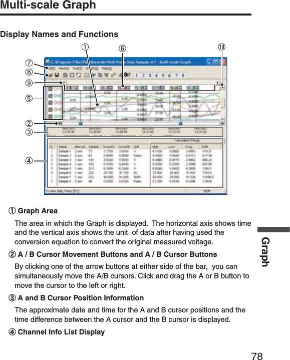
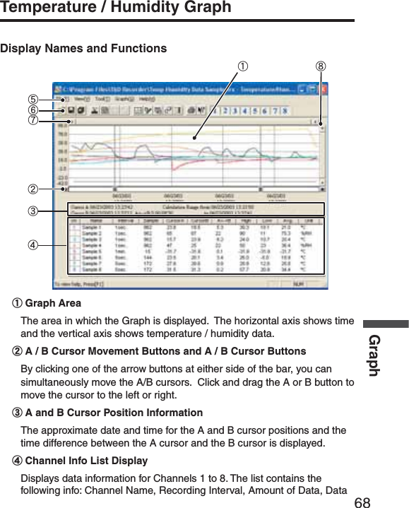
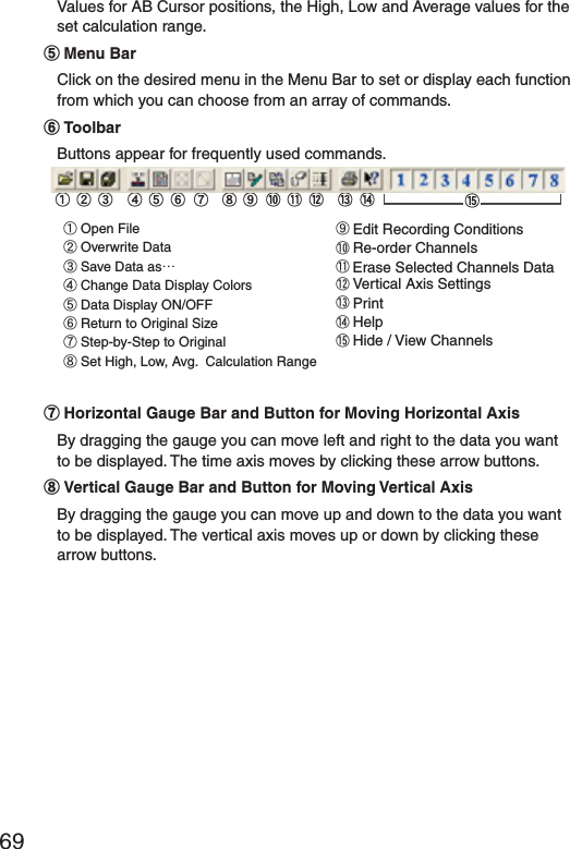
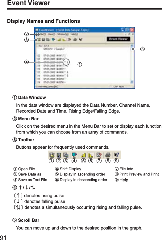
![79Displays data information for Channels 1 to 8. The list contains the following info: Channel Name, Recording Interval, Amount of Data, Data Values for AB Cursor positions, the High, Low and Average values for the set calculation range.ӵThe Vertical Axis Display ON/OFFShift the vertical axis scale display ON/OFF.ӶVertical Axis of Each ChannelThe vertical axis scale is displayed for each channel. By clicking [ ɣɥ ], the axis can be scrolled for each channel.ӷMenu BarClick on the desired menu in the Menu Bar to set or display each function from which you can choose from an array of commands.ӸToolbarButtons appear for frequently used commands. ӱOpen File ӲOverwrite Data ӳData List Display ӴReturn to Original Size ӵStep by Step to Original ӶSet High, Low, Avg. Calculation Range ӷEdit Recording ConditionsӸRe-order ChannelsӹMerge Channel DataӺErase Selected Channel DataӻPrint PreviewӼHelpӽHide / View ChannelsӲӵӷ Ӽӱӳ ӶӴӻӸӹ Ӻ ӽ ӹHorizontal Gauge Bar and Button for Moving Horizontal AxisBy dragging the gauge you can move left and right to the data you want to be displayed. The time axis moves by clicking these arrow buttons.ӺVertical Gauge Bar and Button for Moving Vertical AxisBy dragging the gauge you can move up and down to the data you want to be displayed. The vertical axis moves up or down by clicking these arrow buttons.](https://usermanual.wiki/TandD/RTR50.Users-Manual/User-Guide-760179-Page-88.png)
![80GraphZooming In and Out on the GraphZoom in Using the MouseWith the left button drag the mouse to outline the area you want to zoom in on.Menu Display Using the MouseBy right clicking on the graph, the Menu will be displayed.With [Return to Original Size] or [Step-by Step Return to Original] you can return both the vertical and horizontal axis back to show the entire graph.](https://usermanual.wiki/TandD/RTR50.Users-Manual/User-Guide-760179-Page-89.png)
![81Data List Display[Date / Time] ButtonBy clicking this button, you can shift the display between the recorded date and amount of elapsed time since recording started.Elapsed Time DisplayӱӲRecorded Date Display[Date / Time] ButtonӱThis is a list of the data that was displayed in graph form. The highest value is in RED, lowest is in BLUE, and the average is in ȁPINK.ӲScroll Bar: By dragging it up and down you can move to the data you want.Menu Display Using the MouseBy right clicking on the list, the Menu will be displayed.](https://usermanual.wiki/TandD/RTR50.Users-Manual/User-Guide-760179-Page-90.png)
![82GraphEditing the GraphSelected Channels ON/OFF1. The channel numbers are displayed in the pull down menu of [Selected Channels ON/OFF].2. Check the channel numbers you wish to display.Check*By clicking a Channel Number in the Toolbar, you can carry out the same operation.Scale Display ON/OFF1. The channel numbers are displayed in the pull down menu of [Selected Scale ON/OFF].2. Put a check next to the channel number(s) you wish to be displayed.Check*You can also hide or view channel scales by checking or mchecking the channel number fo the left of the graph.](https://usermanual.wiki/TandD/RTR50.Users-Manual/User-Guide-760179-Page-91.png)
![83Set High, Low, Average Calculation Range1. Set the calculation range in the [Set High, Low, Avg. Calculation Range] box.2. By clicking the [OK] button, the high, low, average calculation range of each channel data will be changed. On the graph display, the calculation range that you have set will be displayed.[OK]button[Entire Graph]buttonEnter the numerical value.[Entire Graph] ButtonTo make the Calculation Range that of the Entire Graph, click the "Entire Graph" button. The dates and times in the [Set High, Low, Avg. Calculation Range] box will be displayed as those of the entire graph.Set by using the AB CursorsIn the Graph Display, open the [Set High, Low, Average Calculation Range] box adjusting the AB cursors to the desired start and end positions. The dates and times of those cursors will be displayed automatically.](https://usermanual.wiki/TandD/RTR50.Users-Manual/User-Guide-760179-Page-92.png)
![84GraphEdit Recording Conditions1. By clicking the [Ch.] button you wish to change, the information for that number will be displayed in the "Edit Items".2. By clicking the [OK] button after changing, the setting will be completed.Channel Number [Restore]button[OK]buttonEnter letters and numerical valuesThe selected channel numberName: Up to 32 letters can be entered.Starting Date/Time: The month, day, year, hour, minute and second can be changed.NOTE:- If you wish to continue to change other channels, repeat the process as in 1.- The [Restore] button is effective only during the setting, and cannot return to the condition it was after the [OK] button has been clicked.](https://usermanual.wiki/TandD/RTR50.Users-Manual/User-Guide-760179-Page-93.png)
![85Re-order Channel Data: From the [Tools] MenuThere are two ways for re-ordering.- Move by dragging the channel number- Move by selecting the channel numberȺMove by dragging the channel numberȻClick on the channel of data you wish to move and drag and drop it to the desired new channel position.ȺMove by selecting the channel numberȻ1. Enter in From: Ȓ, the Channel number you wish to move from, and enter the Channel number to which you want to move in To: Ȓ .2. By clicking the [Re-order] button, the movement will be completed.Drag and drop the channel number to the desired new position.[Change 1 and 2]button[OK]buttonIf you wish to move Ch3 to Ch7. simply set From ɨCh3, To ɨ!Ch7.](https://usermanual.wiki/TandD/RTR50.Users-Manual/User-Guide-760179-Page-94.png)
![86GraphMerge Channel DataYou can merge two different sets of data into one set of data.1. Click theȬɥȭbutton, and select the channels you wish to merge.The following kinds of data cannot be merged:- Recording intervals are different- Measurement times overlap (Merging is possible after adjusting the times in [Editing Recording Conditions])- Data types are different (Merging is possible between same types of data; like temperature/humidity)[OK]button[Merge]buttonEx: If you wish to merge Ch.3 with Ch.72. By clicking the [Merge] button, the merging will be completed.3. Click the [Close] button to fi nish the merging.NOTE:The channel number and other conditions of the merged data will become those conditions set in the channel that you selected in the second box.Erase Selected Channel Data1. Put a check on the channel number you wish to erase.2. By clicking on the [OK] button, the deletion will be completed.](https://usermanual.wiki/TandD/RTR50.Users-Manual/User-Guide-760179-Page-95.png)
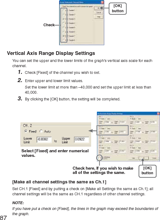
![87[OK]button CheckVertical Axis Range Display SettingsYou can set the upper and the lower limits of the graph's vertical axis scale for each channel.1. Check [Fixed] of the channel you wish to set.2. Enter upper and lower limit values.Set the lower limit at more than –40,000 and set the upper limit at less than 40,000.3. By clicking the [OK] button, the setting will be completed.Select [Fixed] and enter numerical values.Check here, If you wish to make all of the settings the same.[OK]button[Make all channel settings the same as Ch.1]Set CH.1 [Fixed] and by putting a check on [Make all Settings the same as Ch.1]; all channel settings will be the same as CH.1 regardless of other channel settings.NOTE:If you have put a check on [Fixed], the lines in the graph may exceed the boundaries of the graph.](https://usermanual.wiki/TandD/RTR50.Users-Manual/User-Guide-760179-Page-96.png)
![89Scale and Unit ConversionYou can convert the scale and the unit of downloaded data for each channel.1. Select from [Designate by 2 points] tab or [Designate by y=ax+b] tab.[OK]button[Designate by 2 points] tabConversion Info[Designate by y=ax+b] tab2. Set conversion formulas and units.3. By clicking the [OK] button, the setting will be completed. [Conversion Info]Current conversion formulas and units are displayed here."y" indicates the data after conversion, and "x" indicates the voltage entering from the sensor.](https://usermanual.wiki/TandD/RTR50.Users-Manual/User-Guide-760179-Page-98.png)
![90GraphChange Graph ColorsȴColor SampleȵMemo[Close]button[Default]buttonImagePreview[Channel Number]buttonɣɥ1. Click the [Channel Number] button, and click the button of the item that you wish to change.- When changing colors, click on a button to display the color samples. Choose the desired color and click the [OK] button to change the color.- If you wish to change line width, every time you click the Ȭɣȭ button, the width gets wider, and every time you click the Ȭɥȭ button, the width becomes more narrow.2. Confi rm the width in the image preview and click the [Close] button to complete the change.- By clicking the [Return to Default] button, the color settings will return to the Default Settings.[Memo]You can save the settings for Display and/or Print respectively.1. Select "Display" or "Print".2. By clicking the [Save] button, the settings will be saved.ȆBy clicking the [View] button, you can see the settings that had been previously saved. [Save] button [View] buttonFor DisplayFor Print](https://usermanual.wiki/TandD/RTR50.Users-Manual/User-Guide-760179-Page-99.png)
![93Event Viewer:File InfoView File Info about data in the currently displayed data list.1. Select [File Info] from the [View] Menu.2. Click the [OK] button to return to the previous window. File Nameȇ File name of data currently in display Pathȇ Location where file is saved Date Createdȇ The date and time when the data file was created CH. Infoȇ Channel Number, Recording Method and Data Count[OK]button](https://usermanual.wiki/TandD/RTR50.Users-Manual/User-Guide-760179-Page-102.png)
![94GraphEvent Viewer:Print Preview and Print1. In the [File] Menu, select [Print Preview and Print].2. In [Select Channel for Printing] the channel numbers and names will appear. Select the number of the channel(s) you wish to print and click [OK].-It is possible to choose up to 4 channels at one time.[OK]button3. The [Print Preview] will appear. After confi rming it is what you wish to print, click [Print] to start printing.Button Functions [Print] Print box will appear and printing will begin [Previous] Preview the previous page [Specify P] Specify the page you wish to preview in the [Specify Page to be Viewed] box and a preview of that page will appear [Next] Preview the next page [Reduce] Reduce the size of the displayed page [Enlarge] Enlarge the size of the displayed page [Close] Close the Print Preview Window and return to the Main Window](https://usermanual.wiki/TandD/RTR50.Users-Manual/User-Guide-760179-Page-103.png)
![95Saving a FileIf you have clicked [Display the graph after downloading recorded data], and you make any changes to the data after displaying, make sure to save those changes if necessary. NOTE:See p.62 for details about compatible data fi le types.3 Ways to Save FilesIn the [File] Menu, select [Overwrite All Data]Will save any changes to fi le without changing File Name and Saving Location. The same operation can be carried out from [Save] in the Toolbar.In the [File] Menu, select [Save All Data as...]Save with a new File Name.In the [File] Menu, select [Save Displayed Data]Save only that data in the current display. This is handy when you wish to save only the desired data.EX: [Save All Data as...]1. Select [Save All Data as...] in the [File] Menu.2. Specify the [Location] and enter a [File Name].3. Click [Save] to complete the saving process.Specify LocationEnter a File Name [Save]button](https://usermanual.wiki/TandD/RTR50.Users-Manual/User-Guide-760179-Page-104.png)
![96GraphSaving Event Viewer DataIn the [File] Menu, select [Save All Data as...]Save with a new File Name. Specify LocationEnter a File Name [Save]button1. Select [Save All Data as...] in the [File] Menu.2. Specify the [Location] and enter a [File Name]3. Click [Save] to complete the saving process.](https://usermanual.wiki/TandD/RTR50.Users-Manual/User-Guide-760179-Page-105.png)
![97Saving Data in Text FileBy saving the recorded data as text fi le, you can create a fi le type that can be read by common spreadsheet software. When saving Temp/Humid Graph and Multi-scale Graph data as Text File1. Select [Save in Text File] in the [File] Menu.2. Select the [Text File Type] and [Range to be Saved], and click [OK].- Comma, Tab, Space, and Semi-colon are codes used by common spreadsheet software, such as Excel and Lotus, when reading Text File to divide cells.3. Designate the location to which the fi le should be saved and click [Save] to create and save the data as a Text File document.- The extension for the created fi le will be [.TXT].NOTE:- Text File cannot be read into T&D for Windows graphs.- The display layout differs between the Temp/Humid Graph or the Multi-scale Graph.EXȇTemp/HumidGraph Text File Settings WindowȁSelect the Text File TypeSelect the Range to be Saved](https://usermanual.wiki/TandD/RTR50.Users-Manual/User-Guide-760179-Page-106.png)
![98GraphWhen saving Event Viewer data as Text File1. Select [Save Data in Text File] in the [File] Menu.2. Select the [Text File Type] and click [Designate File] and [OK].- Comma, Tab, Space, and Semi-colon are codes used by common spreadsheet software, such as Excel and Lotus, when reading Text File to divide cells.[OK]button[Designate File]buttonSelect the Text File Type3. Designate the location to which the fi le should be saved by clicking [Designate File] and click [OK] to create and save the data as a Text File document. NOTE:- The extension for the created fi le will be [.TXT].- Text File cannot be read into T&D for Windows graphs.](https://usermanual.wiki/TandD/RTR50.Users-Manual/User-Guide-760179-Page-107.png)
![99Opening a FileTo open a previously saved fi le, designate the fi le name to open it. To open multiple fi les at once, hold down the Ctl-key and select the fi les you with to open.NOTE:See p.62 for details about compatible data fi le types.Opening a File with the Temp/Humid Graph and Multi-scale Graph1. Select [Open] in the [File] Menu2. Select the name of the data you wish to open and click [Open] to view the data in graph form.[Open]buttonSelected File InfoSelected File NameSelect a File](https://usermanual.wiki/TandD/RTR50.Users-Manual/User-Guide-760179-Page-108.png)
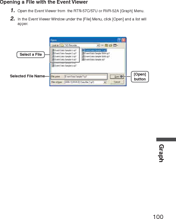
![100GraphOpening a File with the Event Viewer1. Open the Event Viewer from the RTR-57C/57U or RVR-52A [Graph] Menu.2. In the Event Viewer Window under the [File] Menu, click [Open] and a list will apper.[Open]buttonSelect a FileSelected File Name](https://usermanual.wiki/TandD/RTR50.Users-Manual/User-Guide-760179-Page-109.png)
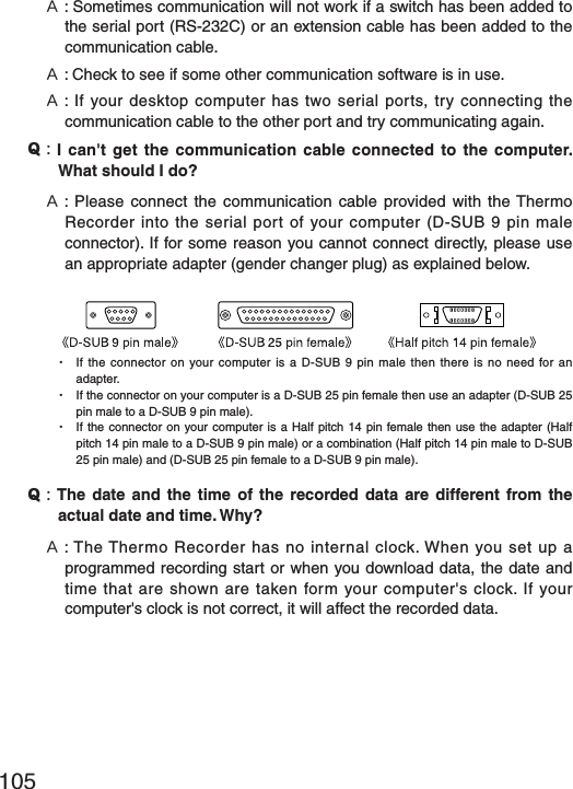
![103Troubleshooting˭: The computer won't communicate via the Serial Port. What should I do? ˝: Try two or three times to fi nd the port connection by using the Auto-detect function.˝: Check to make sure that the power of the main unit is ON.˝: Check to make sure that the connection is proper. Communication will take place only through the serial port (RS-232C) and will not work through the printer port or any other port.˝: Check to make sure that you can control the Thermo Recorder via the software.˝: If you have access to another computer, try seeing if communication works with the other computer.˝: If you have a computer with energy saving function settings, make sure that the serial port has not been turned off. Especially on NEC brand PC98 notebook computers the default setting maybe such.˝: Check to make sure that the serial port has not been rendered unusable by the BIOS setting.˝: Make sure that the serial port setting has not been made to render the port unusable. With some computers, especially all-in-one computers the serial port serves as the modem jack.How to check1. View in the Device Manager Window. For Windows XP or 20001.On the Desktop, right click on [My Computer] and click on [Properties].2.In the System Properties Window, click on the [Hardware] Tab, then click on the [Device Manager] button to view the Device Manager Window.](https://usermanual.wiki/TandD/RTR50.Users-Manual/User-Guide-760179-Page-112.png)
![104OthersFor Windows 98SE or ME1.Open the [Control Panel] and double click on [System] to display the [System Properties].2.Click the [Device Manager] Tab to view the Device Manager Window.2. In the [Device Manager], click on [Port (COM&LPT)] and check to see if under that appears [Com Port (COM1)] or [Com Port (COM2)]. If a port appears, it should be usable.- If a mark [ Ȋ] or [ ȿ] appears next to the port, this communication port is unusable. If you cannot use a communication port please contact your computer company.- To fi nd out more details about an unusable communication port: Select the port with a [ Ȋ] mark, and then click on [Properties] to view the details about that port.˝: If your computer has an internal modem, make sure that the communication port is not being used by it. When the communication port is being used as the modem port, that port cannot be used. Either quit using the modem or use another port.ɦAn example of the modem using a communication port (COM 1).˝: If your computer has no serial port, use a Serial-USB conversion cable and carry out communication via USB connection. We recommend [I.O DATA USB-RSAQ3] , [ELECOM UC-SGT] and [IOGEAR UC-232A] Serial-USB conversion cables. If you are using an NEC Lavie J Notebook Computer(NEC LJ-500), please use [I.O DATA USB-RSAQ3].](https://usermanual.wiki/TandD/RTR50.Users-Manual/User-Guide-760179-Page-113.png)
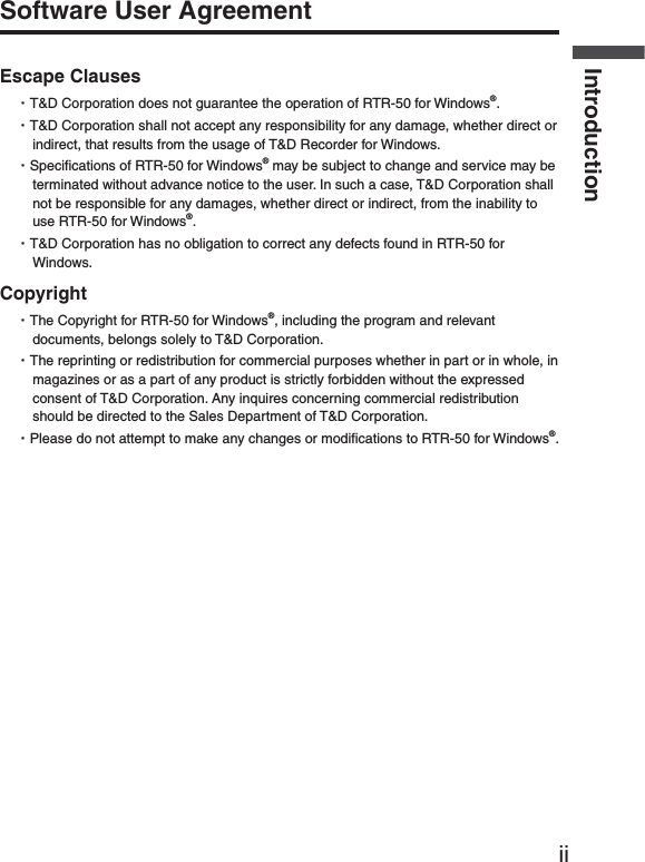
![108OthersRTR-50చ؊ܥਅ RTR-5,RVR-5ܥෝ ྫȇ ΟȜΗݟષ̬ȂκΣΗນাȂܱٳইȂྫಎࠑܥෝȇΟȜΗݟષ̬Ȃܱٳইഩ࡙ USB ΨΑΩχȜȂౙ२ۋഩ౻ȿ 2ȂAC ͺΘίΗ (AD-0601) [ Υ·Η EIAJ ഩգߊ 2Ηͼί ]ͼϋΗέͿȜΑ USB [MiniB Υ·Η ] / Ώςͺσ [ηΣΏςͺσ ](19200bps)ྫ༷ අഩႁྫ (ARIB STD-T67) 426MHz ఝ 4 ΙλϋΥσྫഩݻၗ 100m( ࡉ̱͈ၻ̞ೄ̞̀ͅ )শۼ ྫȇΟȜΗ FULL ́ 420 ຟ(ಎࠑܕྚঀဥশ )ಎࠑܕͬঀဥ̳ͥાࣣȂಎࠑܕˍరྀͅષܱ͈শۼ̦حॳ̧̯̞̳ͦ̀͘ȃȇΟȜΗ FULL ́ 160 ຟນাܥෝ ႂ LED( ྫȂPC শͅത )ഩ౻ྵ ౙ२ۋഩ౻ x 2 ͈൲ै́ 15ۼ͈ಎࠑܕ̱͂̀ঀဥ̱̹ાࣣȂ 6ώུఘ༹ 95[mm] ȿ65[mm] ȿ24.5[mm]( ̯ࣞȿ໙ȿ࢚̯ )ུఘৗၾ 60g( ഩ౻܄̴͘ )൲ैഩգ 2.5V ȡ7.0Vકഩၠ ྫশ 50mAུఘ൲ै۪ޏ أഽ -10-60Ɏ(ٸ໐ഩ࡙ঀဥশ -30-60Ɏ)ഽ 20-80%RH( ࠫႺ̱̞̭̈́͂ )ັ௺ USB ΉȜήσȂΕέΠ;Ϳͺ CDȂ৾ե୰ྶίΏοϋ ΏςͺσΉȜήσ (TR-07C)ȂAC ͺΘίΗ (AD-0601)Ȃٸ໐ഩ࡙ξΣΛΠ (AD-0620)](https://usermanual.wiki/TandD/RTR50.Users-Manual/User-Guide-760179-Page-117.png)