Tektron Micro Electronics DST1000 DIGITAL STEREO TRANSMITTER User Manual DST1000 TxManual
Tektron Micro Electronics Inc DIGITAL STEREO TRANSMITTER DST1000 TxManual
UserManual.wiki
>
Tektron Micro Electronics
>
DST1000 User Manual
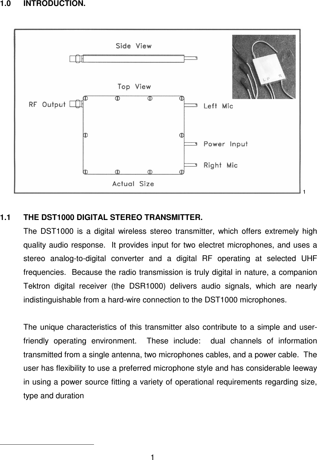
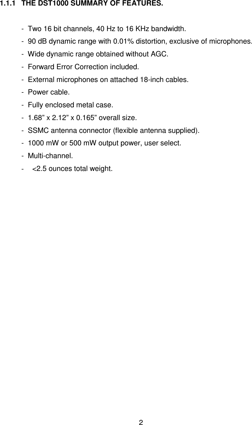
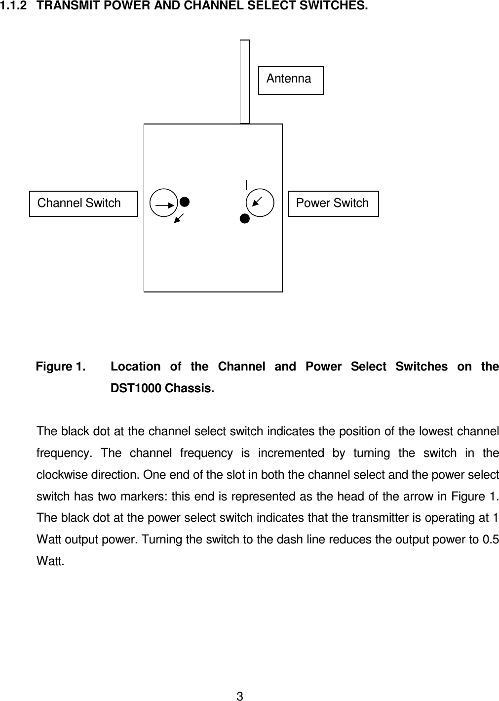
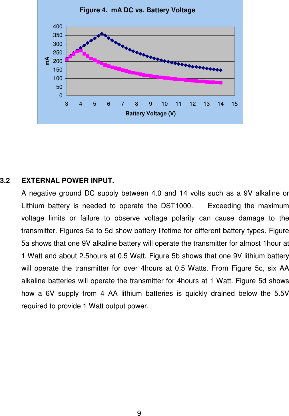
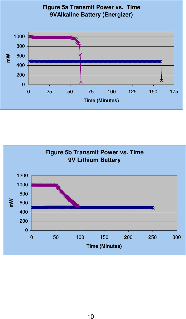
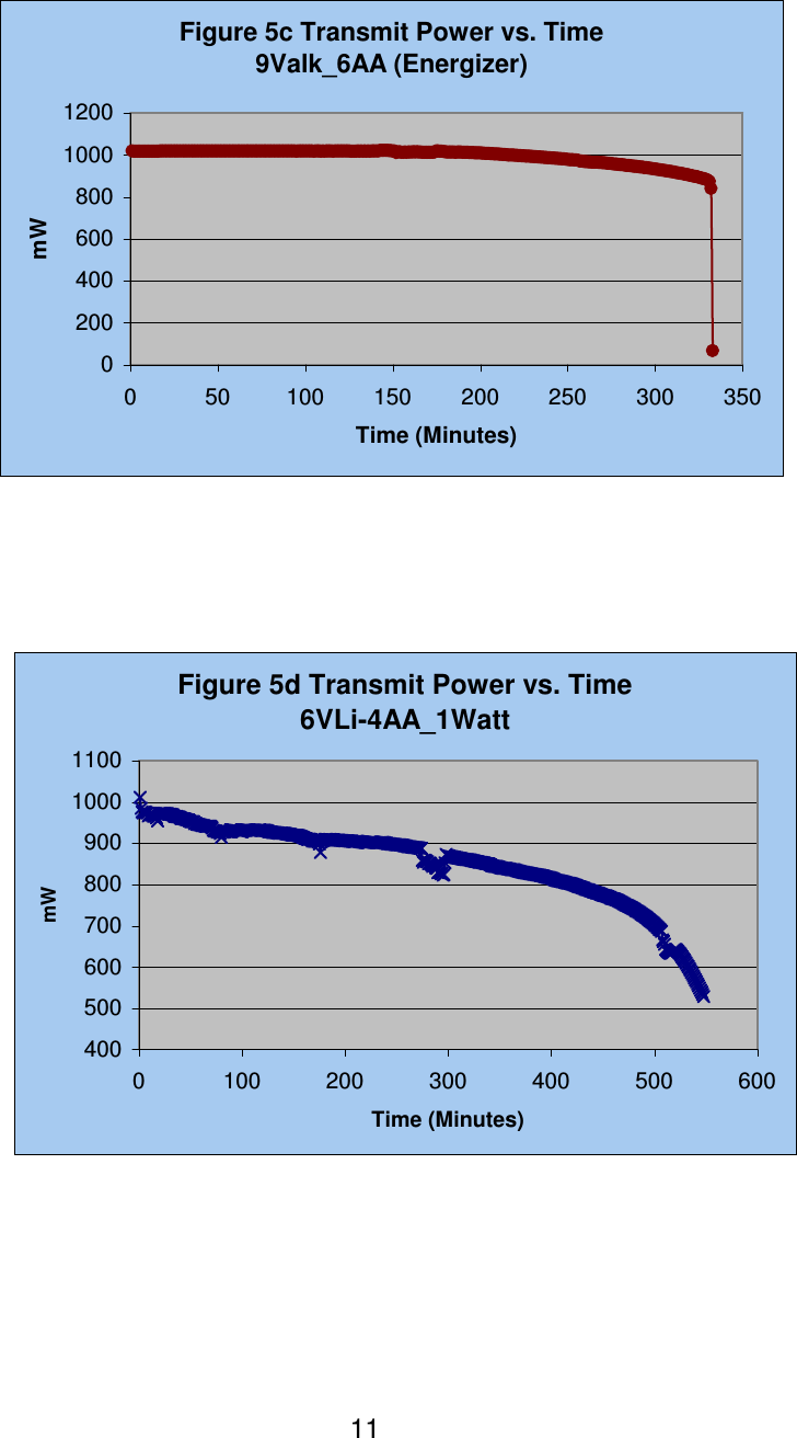
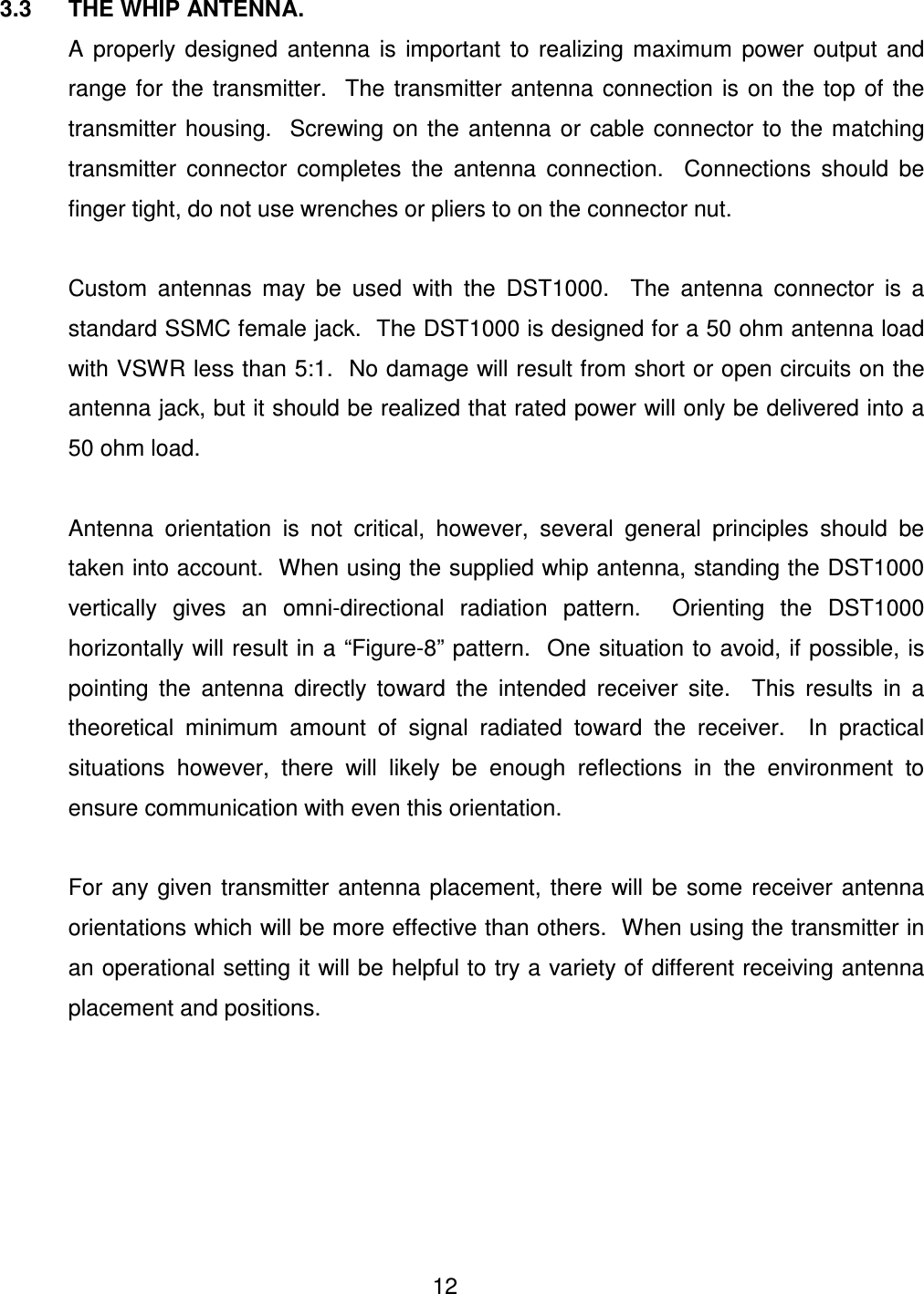
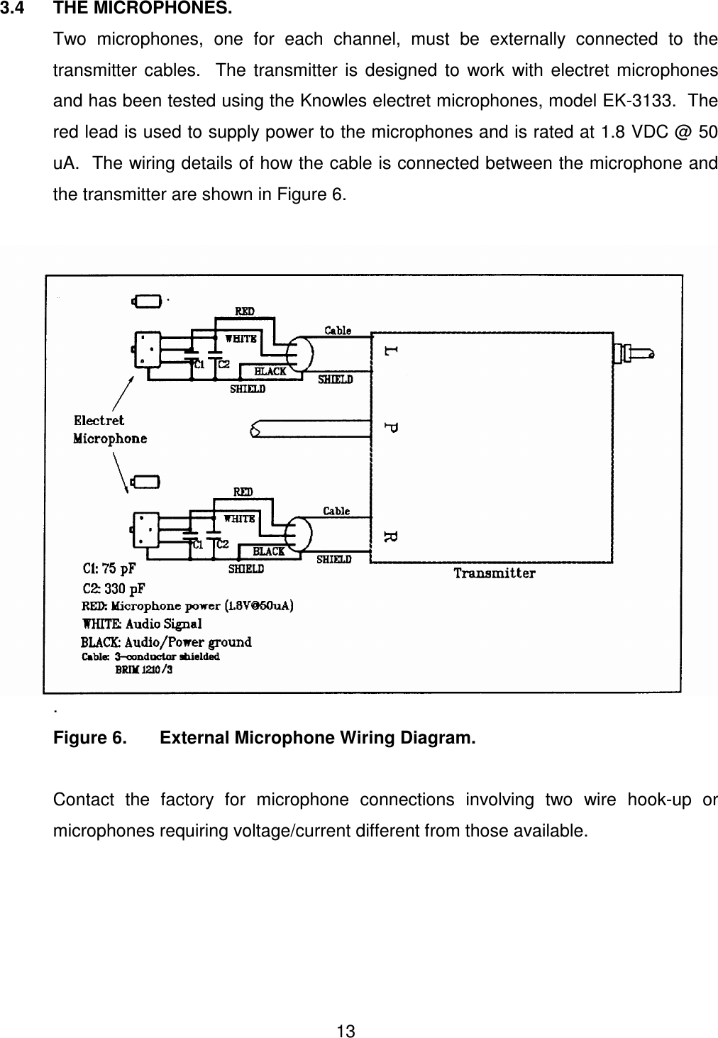
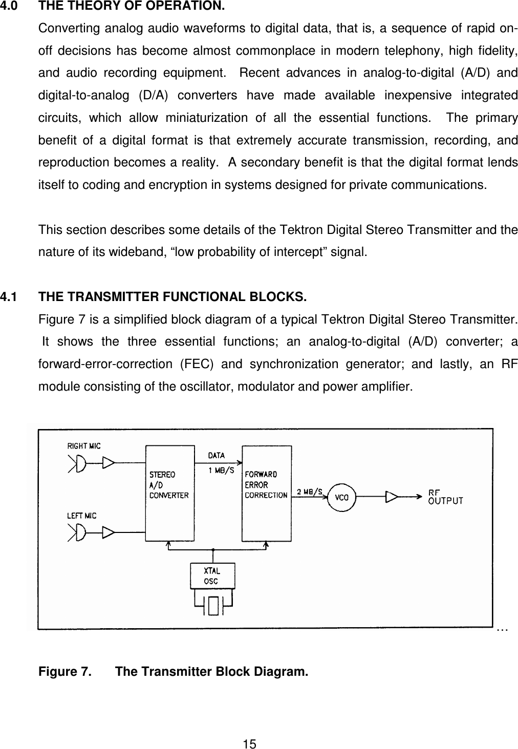
USERS MANUAL
Navigation menu
Upload a User Manual
Namespaces
Wiki Guide
HTML
PDF
Info
Views
User Manual
Discussion / Help
Navigation